User Manual Lufft CHM 8k Ceilometer
←
→
Page content transcription
If your browser does not render page correctly, please read the page content below
User Manual
Lufft CHM 8k Ceilometer

General Information -1-
Contents
1 General Information .......................................................................................................................4
 1.1 Symbols used............................................................................................................................5
2 Safety 5
 2.1 Standards and Directives ..........................................................................................................5
 2.2 Safety instructions for the laser system ....................................................................................5
 2.3 Requirements for the personnel ................................................................................................5
 2.4 Safety instructions for transport, installation, commissioning and cleaning .............................5
 2.5 Description of the warnings .......................................................................................................6
 2.5.1 Description of warning symbols ................................................................................................6
 2.5.2 Description of precautionary statements ...................................................................................6
 2.6 Product labeling CHM 8k ..........................................................................................................7
 2.7 Designated use .........................................................................................................................7
3 Technical Data ................................................................................................................................8
 3.1 Ordering information .................................................................................................................8
 3.2 Technical data ...........................................................................................................................8
4 Technical Description ................................................................................................................. 11
 4.1 Construction of the CHM 8k ................................................................................................... 11
 4.2 Functional units of the inner housing ..................................................................................... 11
 4.2.1 Functional diagram................................................................................................................. 12
 4.2.2 Function control and device status ........................................................................................ 13
5 Transport / Scope of Delivery ..................................................................................................... 14
6 Installation ................................................................................................................................... 15
 6.1 Installing the CHM 8k ............................................................................................................. 15
 6.1.1 Preparatory work .................................................................................................................... 15
 6.1.2 Installing on the foundation.................................................................................................... 16
 6.2 Electrical installation .............................................................................................................. 18
7 Commissioning and Decommissioning .................................................................................... 22
 7.1 Starting up with the RS485 connection .................................................................................. 22
 7.2 Starting up with the LAN connection ...................................................................................... 23
 7.3 Shutdown ............................................................................................................................... 24
 7.4 Disposal ................................................................................................................................. 24
8 Communication via RS485 & Ethernet ...................................................................................... 25
 8.1 List of configurable parameters .............................................................................................. 25
 8.2 Device configuration with RS485 ........................................................................................... 30
 8.2.1 Reading out a parameter ....................................................................................................... 30
 8.2.2 Setting a parameter ................................................................................................................ 30
 8.2.3 Changing the baud rate .......................................................................................................... 31
 8.2.4 Restarting the embedded Linux system / factory settings ..................................................... 31
 8.2.5 Changing the time settings..................................................................................................... 32
 8.3 Data query RS485 .................................................................................................................. 32
 8.3.1 Polling mode .......................................................................................................................... 32
 8.3.2 Automatic output mode .......................................................................................................... 33
 8.3.3 Standard data telegram ......................................................................................................... 33
 8.3.4 Extended data telegram ......................................................................................................... 35
 8.3.5 Raw data telegram ................................................................................................................. 38
 8.3.6 Additional data telegrams ...................................................................................................... 39

General Information 2
Operating Manual CHM 8k R2.0 / 02-2021

 8.4 Structure of the NetCDF format ............................................................................................. 39
 8.4.1 General .................................................................................................................................. 39
 8.4.2 Basic principles ...................................................................................................................... 39
 8.4.3 File names .............................................................................................................................. 39
 8.4.4 Format structure ..................................................................................................................... 40
 8.4.5 Special values of the evaluation parameters ......................................................................... 43
 8.5 Status code ............................................................................................................................ 44
 8.5.1 Escalated status codes .......................................................................................................... 45
 8.6 Firmware update .................................................................................................................... 48
 8.7 Communication via Ethernet web interface ........................................................................... 48
 8.7.1 Device overview and access rights (Device tab) ................................................................... 48
 8.7.2 Access to measurement data (NetCDF files, viewer) ............................................................ 49
 8.7.3 Configuring the CHM 8k (Config tab) ..................................................................................... 50
 8.7.4 Status and error messages (process status) ......................................................................... 53
 8.7.5 Time server ............................................................................................................................ 54
 8.8 AFD mode .............................................................................................................................. 55
 8.9 Telegram via Ethernet ............................................................................................................ 56
 8.10 NetCDF file tools .................................................................................................................... 56
9 Data Evaluation / Sky Condition Algorithm (SCA) ................................................................... 58
 9.1 Laser remote sensing ............................................................................................................. 58
 9.2 Preparation of the measured data ......................................................................................... 58
 9.3 Cloud ceilings / cloud base heights ....................................................................................... 59
 9.4 Cloud penetration depths ....................................................................................................... 59
 9.5 Parameters for data evaluation .............................................................................................. 60
 9.6 Determination of the maximum detection range (MXD) ......................................................... 60
 9.7 Vertical optical visibility (VOR) ............................................................................................... 60
 9.8 Precipitation and fog .............................................................................................................. 60
 9.9 Mixing layer height ................................................................................................................. 61
 9.10 Cloud cover (BCC / TCC) ...................................................................................................... 61
 9.11 Sky Condition Index (SCI) ..................................................................................................... 63
10 Cleaning, Maintenance and Service Instructions .................................................................... 64
 10.1 Cleaning ................................................................................................................................. 64
 10.2 Maintenance intervals and measures .................................................................................... 66
11 Appendix ....................................................................................................................................... 68
 11.1 CHM 8k device hardware version .......................................................................................... 68
 11.2 CHM 8k software version ....................................................................................................... 68
12 Index of Figures ........................................................................................................................... 71
13 Index of Tables ............................................................................................................................ 72

General Information 3
1 General Information

 This operating manual is part of the equipment. It must always be kept close to
 the equipment so that it can be accessed quickly when needed.
 This operating manual must be read, understood and observed in all respects
 by all persons responsible for the equipment and all persons who work on it.
 This applies, in particular, to the chapter "Safety".

Editorial deadline: February 2021

Documentation number: 8349.MEP

This operating manual is valid for the following versions of the equipment with the order numbers:

 8349.01-010 8349.02-010
 8349.11-010 8349.12-010
 8349.11-003 8349.22-010
 8349.21-010 8349.32-010
 8349.31-010
The description of the DSL modem is given in a separate supplementary sheet.

Manufacturer
OTT HydroMet Fellbach GmbH
Gutenbergstraße 20
70736 Fellbach, Germany

Telefon +49 711 518 22 – 831
E-Mail met-service@otthydromet.com

 Date Issue Notes

 July 2018 R1 Initial release

 February 2019 R1.4 Revision, adaptation to new firmware
 Revision chapter 10, technical data, safety advise,
 October 2019 R1.6
 adaptation to new firmware
 January 2020 R1.7 Revision, adaptation to new firmware

 September 2020 R1.8 Revision, adaptation to new firmware
 Revision, adaptation to new firmware 1.070/1.080,
 February 2021 R2.0
 address change

Copyright

© 2021
This manual is protected by copyright. No part of this manual may be reproduced in any form (photograph,
photocopy, microfilm or any other method) or processed, duplicated or distributed using electronic
systems without the written permission of OTT HydroMet Fellbach GmbH. Violations will be prosecuted.
The manual was prepared with due care. No liability is assumed for damages resulting from failure to
observe the information contained in the manual.

General Information 4
Operating Manual CHM 8k R2.0 / 02-2021 1.1 Symbols used Remarks for the smooth use of the equipment Required action step 2 Safety 2.1 Standards and Directives The device is designed according to the recognized rules of technology and safety and is manufactured in series unchanged. The applied rules are listed in the currently valid declaration of conformity. Declarations of conformity can be downloaded from our homepage: https://www.lufft.com/products/cloud-height-snow-depth-sensors-288/lufft-ceilometer-chm8k-2405/ In Europe, the declaration of conformity is enclosed in the accompanying documents. 2.2 Safety instructions for the laser system The CHM 8k Ceilometer is classified as a Class 1M laser product according to IEC 60825-1:2014-05. It complies with 21 CFR 1040.10 except for deviations pursuant to Laser Notice No. 50, dated June 24, 2007. The sensor emits a beam of invisible laser radiation (905 nm) with small divergence (< 1.5 mrad) and a beam diameter of 60 mm (FWHM). A warning label is attached to the front of the instrument (see section 2.6). Class 1M radiation is regarded safe except when viewed with telescope optics. The instrument may only be operated in a protected outside area. The following precautions must be taken when operating the sensor: • Never view the laser beam with optical instruments, especially binoculars • Avoid looking directly into the laser beam • Do not operate the instrument with the inner sensor door open • Do not operate the sensor horizontally (maximum tilt angle 20°) • Keep the beam path free of reflecting materials The laser radiation emitted by the sensor is generated by an embedded Class 3B laser module. Even short exposure to Class 3B laser radiation can lead to injuries to the eye and skin. Maintenance and service of the sensor may only be carried out by trained personnel. Under no circumstances may the laser module be removed from the measuring unit or any protective covers removed! 2.3 Requirements for the personnel • The CHM 8k may only be installed and commissioned by trained personnel who have received instructions in safety-related matters. Electrical connection of the device may only be carried out by a qualified electrician. • Maintenance and adjustment work on the CHM 8k may only be carried out by the service staff of OTT HydroMet Fellbach GmbH or by the customer’s authorized and trained personnel. All maintenance work requires a technical qualification in electrical safety. • Every person assigned to install and commission the CHM 8k must have read and understood the complete user manual. • During all work on the equipment, personnel must not be overtired and must not be under the influence of alcohol, medicines or intoxicants. The personnel must have no physical limitations that temporarily or permanently restrict their attention and judgment. 2.4 Safety instructions for transport, installation, commissioning and cleaning • The CHM 8k may only be loaded and transported in the packed condition and in the transport position (see Figure 5) using suitable lifting gear and transport equipment. • Inside the shipping container/truck the CHM 8k must be adequately protected against slipping, shock, or other mechanical impacts, e.g. by using straps. • If the CHM 8k is not installed immediately, it must be stored protected from external influences and adequately secured. • At least two people are required to install the CHM 8k. Safety 5
Operating Manual CHM 8k R2.0 / 02-2021

 • Once the CHM 8k has been installed, it must be checked. Make sure that no safety-related
 changes have taken place on the device.
 • The inner housing door may only be opened by the service staff of OTT HydroMet Fellbach
 GmbH or by the customer’s authorized and trained personnel.
 • Never operate the sensor if a cover window is broken. Return the sensor to OTT HydroMet
 Fellbach GmbH for repair.
 • Explosion hazard. Do not install the CHM 8k in hazardous locations.

2.5 Description of the warnings

2.5.1 Description of warning symbols

 Symbol Use

 Warning of a general hazard

 Warning of laser beam

 Warning of dangerous electrical voltage

 Warning of hot surface

 Electrical equipment marked with this symbol may not be
 disposed of in European domestic or public disposal systems.
 Return old or end-of-life equipment to the manufacturer for
 disposal at no charge to the user.

2.5.2 Description of precautionary statements

 WARNING
 Indicates a hazardous situation that, if not avoided, could result in death or serious injury.

 CAUTION
 Indicates a hazardous situation that, if not avoided, could result in minor or moderate injury.

 NOTICE
 Indicates a situation which, if not avoided, may cause damage to the instrument. Information that
 requires special emphasis.

Safety 6
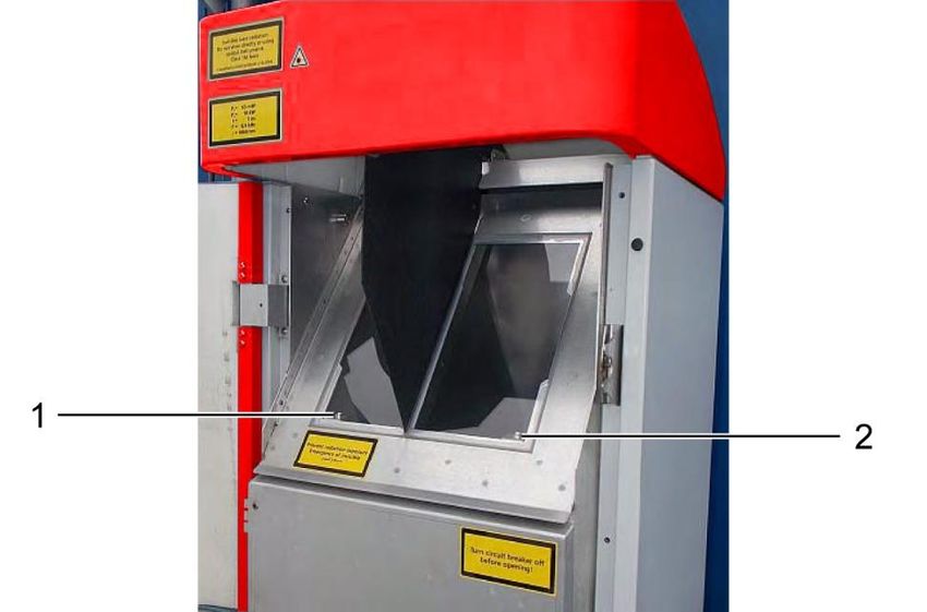
Operating Manual CHM 8k R2.0 / 02-2021

2.6 Product labeling CHM 8k
The product labels are show in Figure 1. The type plate and the protective earth connection are located
on the back of the housing foot.

 Never operate the sensor if a cover
 window is broken! Refer to section 10
 for a detailed explanation.

Figure 1 Safety labeling.

2.7 Designated use
The operational safety of the CHM 8k is only guaranteed if used as designated in accordance with the
instructions in this operating manual.
The device is designed for single phase operation on a public low-voltage network in accordance with
IEC38, 6th edition, 1983.
The ceilometer may be used only in a protected outside area. In standard operation, the laser beam is
aligned to the zenith, i.e. the device measures vertically. It can be tilted with adequate accessories to a
maximum tilt angle of 20°. Any use beyond this limit is considered non-designated use! The operator
bears sole responsibility for any resulting damage.
Horizontal use represents a safety risk for third parties and is expressly excluded.
For trouble-free operation, follow a regular cleaning and maintenance cycle (see chapter 10).

Safety 7
Operating Manual CHM 8k R2.0 / 02-2021

3 Technical Data
3.1 Ordering information

 Equipment Versions
 Order number Description Power supply Cable length
 8349.01-010 CHM 8k EU Basic 230 VAC ±10% 10 m
 8349.11-010 CHM 8k EU + DSL Modem 230 VAC ±10% 10 m
 8349.11-003 CHM 8k EU + DSL Modem 230 VAC ±10% 3m
 8349.21-010 CHM 8k EU + Battery Backup 230 VAC ±10% 10 m
 8349.31-010 CHM 8k EU + DSL Modem + Battery Backup 230 VAC ±10% 10 m

 8349.02-010 CHM 8k US Basic 115 VAC ±10% 10 m
 8349.12-010 CHM 8k US + DSL Modem 115 VAC ±10% 10 m
 8349.22-010 CHM 8k US + Battery Backup 115 VAC ±10% 10 m
 8349.32-010 CHM 8k US + DSL Modem + Battery Backup 115 VAC ±10% 10 m
Table 1 Equipment versions.

Composition of order numbers:
8349.xx-yyy
8349 = CHM 8k basic unit (instrument, documentation, transport box)
xx = Special interface, other features (modem, battery backup, etc.)
xx = Country code (EU or US)
yyy = Cable length (003 = 3m; 010 = 10 m; 050 = 50m)

3.2 Technical data

 Measurement parameters
 Measuring range 0 m … 10 km (0 … 32808 ft)
 Cloud detection range 5 m … 8 km (16 … 26246 ft)
 Resolution (measured) 5m
 5 m – 30 m in 5 m steps (can be set by the user)
 NetCDF data resolution (*)
 15 m (default setting)
 NetCDF high resolution data 5 m (defined for limited HR vector of data)
 Logging time and reporting 2 s to 600 s (programmable)
 cycle (*) Default value: 15 s
 Measurement objects Aerosols, clouds (droplets, ice crystals)
 Backscatter raw data
 Cloud heights up to 9 layers including penetration depth, max.
 Measured / set parameters
 detectable range (MXD), vertical visibility (VOR), Sky Condition
 Index (SCI), cloud cover (TCC, BCC), ...
 Measuring principle Lidar (optical, time of flight)
 Optical parameters
 Light source Laser diode
 Wavelength 905 nm
 Pulse energy 2 μJ max. (1.6 μJ typical)
 Pulse repetition rate 8 kHz
 Filter bandwidth 25 nm
 Field-of-view receiver (FOV) 1.1 mrad
 Extended NOHD 400 m (for 50 mm aperture)

Technical Data 8
Operating Manual CHM 8k R2.0 / 02-2021

 Data interfaces
 Standard interfaces RS485 half-duplex (ASCII); LAN (http, (S-)FTP, NetTools)
 Optional interfaces DSL, RS485 full-duplex (4 wire)
 Electrical parameters
 Power supply 230 VAC ±10 % or 115 VAC ±10 %
 Line frequency 50 Hz, 60 Hz
 Max 450 VA with activated case heater (default);
 Power consumption
 Max 300 VA without activated case heater
 Power consumption in W Measuring unit heater: 250 W @115 / 230 VAC
 (depends on supply voltage) Case heater: 150 W @115/ 230 VAC
 UPS functionality (optional) Internal backup battery for the electronics (> 1 hour)
 Equipment safety
 General safety IEC 61010-1:2010 + A1
 Laser Protection Class 1M according to IEC 60825-1:2014; complies with 21 CFR 1040.10
 Protection housing IEC/ EN 60529: IP 65; IEC/EN 61010-1: IK06 (1 Joule)
 Protection electrical safety Protection class I (protective earth needed)
 Overvoltage Category II
 Pollution degree in IP65 2
 housing
 EMC EN 61326 Class B (industrial use)
 Conformity CE
 Operating conditions
 Temperature range -40 °C to +60 °C
 Relative humidity 0% – 100%
 Wind 60 m/s
 Maximum operating altitude 5000 m
 Dimensions
 Enclosure dimensions
 W x H x L = 0.5 m x 0.5 m x 1.55 m
 (footprint x height)
 Packaging dimensions W x H x L = 0.75 m x 0.86 m x 1.80 m
 Weight
 70 kg (complete system)
 Weight
 9.5 kg (measuring unit – heaviest replacement part)
 Installation requirements
 Suitable low-voltage TN-S system: grounded mains, grounded CHM 8k enclosure,
 distribution systems neutral and protective conductor separate
 TN-C system: grounded enclosure CHM 8k, neutral and protective
 conductor combined in one conductor
 Connection type Fixed connection, grounding by means of ground connection clamp
 (see Figure 12)
 Resources to be provided by the operator
 Lightning protection - Internal lightning protection is provided
 - External lightning protection must be provided
 Grounding Grounding system according to DIN V VDE 0185-3
 Requirements for installation - Isolation device for disconnection from low-voltage network in
 close proximity to the CHM 8k
 - Easily accessible
 - Marked as belonging to the CHM 8k
 - Pre-fuse only needed for 230 VAC variant: 10 A gG time-lag
Table 2 Technical data.

Technical Data 9
Operating Manual CHM 8k R2.0 / 02-2021

(*) the combination of high temporal and range resolution over the full range is limited due to file size and
processing time. Any combination of > 70MB daily NetCDF fle sizes is not supported by Lufft.
Example (standard operation mode): 15 m range resolution over 10 km range with 15 s time resolution
results in 17 MB daily NetCDF file sizes.

Technical Data 10
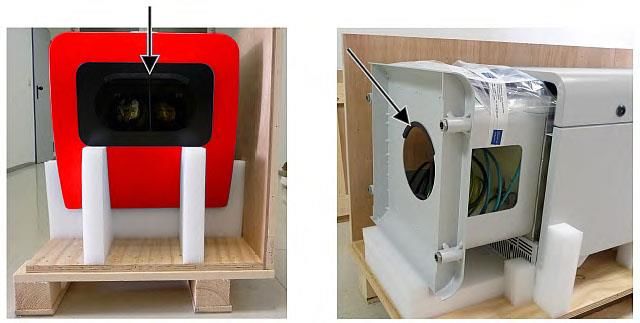
Operating Manual CHM 8k R2.0 / 02-2021

4 Technical Description
The CHM 8k ceilometer is mainly used to measure cloud bases, cloud penetration depths, cloud cover
statistics, the vertical visibility and the aerosol layer. The calculated data are transferred by remote
transmission via standard digital interfaces.
The CHM 8k uses the lidar method as a measuring principle (Lidar: light detection and ranging): short
light pulses are emitted into the atmosphere where they are scattered by aerosols, droplets and air
molecules. The portion of the light that is scattered back to the ceilometer is further analyzed. The
propagation time of the laser pulses is measured and used to calculate the distance of the scattering
event.
The height profile of the backscattered signal is analyzed to calculate the attenuated backscatter
coefficient as the first output parameter from the instrument. The different target parameters like the cloud
base layers and the aerosol layer height are calculated from these data.
The CHM 8k detection system is based on an analog detection method with a 25 nm bandwidth optical
filter in front of the detector. It is designed to suppress background light effectively, while being compatible
with the broader emission spectrum of InGaAs laser diodes. The analog detection system offers high
dynamical range without saturation of the detector.

The CHM 8k ceilometer is:

 • A compact device including heater and window blower.
 • Capable of operating under the ambient conditions specified in the technical data (see 3)
 • Based on modules, e.g. the laser optical unit (LOM) inside the device can be replaced (refreshed)
 at the end of the laser diode lifetime
 • A device designed for 24/7 continuous operation

4.1 Construction of the CHM 8k
The housing of the CHM 8k is made of corrosion-resistant aluminum in double-shell construction.
The function of the outer shell is to dampen the external influences of:

 • Solar radiation
 • Wind
 • Precipitation
 • Mechanical shock

on the inner shell, which carries the measuring unit. The chimney effect between the outer shell and the
inner housing supports this process and avoids high temperature in the inner housing.
The housing cover protects the inner housing against dust and precipitation and mechanical damage on
the windows. The housing cover contains the opening for laser exit and laser entry. The partition in the
cover decouples the transmission area from the sensitive receiving area. An air baffle inside the cover
directs the airflow from both fans directly onto the glass windows of the inner housing.
The inner housing incorporates all the equipment needed to operate the CHM 8k. The cable feed-
throughs for data line, power supply and connection of the external fans are realized via cable glands.
For pressure equalization, the inner housing has a pressurization element with a GoreTex® membrane.
The upper end of the inner housing forms a two-part viewing window made of coated float glass. The
windows are inclined at the Brewster angle. This ensures low-loss laser light transmission and optimal
self-cleaning of the windows. The fan located at the rear of the device supports the cleaning of the
windows: the fans are switched on an hourly interval and in rain / snow. The fans are also used to remove
heat from the inner housing. The fans are serviced by a service technician via the removable rear panel
of the CHM 8k.
The outer door allows access to the inner housing and the glass windows, e.g. for cleaning purposes.
Access to the interior of the inner housing is possible via the inner door. The outer and inner doors are
secured with different locking mechanisms. In this way, access to the interior of the inner housing by
cleaning personnel who have not been instructed in safety-related matters is excluded. The inner door
may only be opened by the service staff of OTT HydroMet Fellbach GmbH or by the customer’s
authorized and trained personnel.

4.2 Functional units of the inner housing
The functional units of the device are:
 • Transmitting and receiving unit (measuring unit - LOM)
 • Control board and related components

Technical Description 11
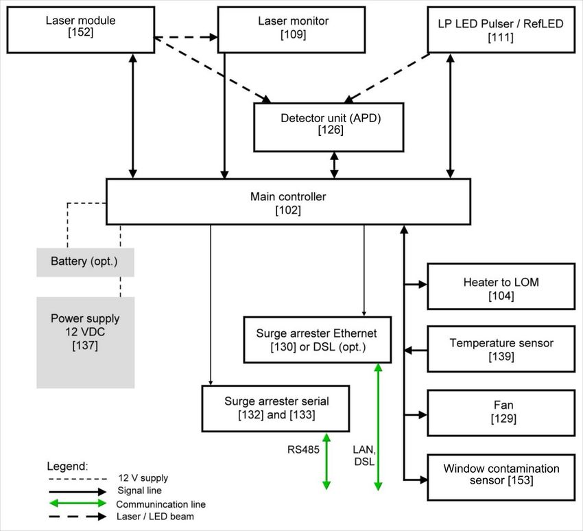
Operating Manual CHM 8k R2.0 / 02-2021

 • Power supply 12 - 15 VDC for the electronics
 • Transformer 48 VCD for fans
 • Fan and temperature sensors
 • Lightning and overvoltage protection device for power cable, LAN, RS485

The functional units are of modular design, fastened separately to the inner housing and can be removed
and replaced individually for servicing purposes.

4.2.1 Functional diagram

Figure 2 Functional chart, the numbers in brackets corresponds to the numbering in the spare parts list (provided in the service
manual or as an extra list).

Figure 2 clearly shows that the main controller is the central unit. The main controller controls and monitors
all device functions shown here and provides corresponding status values.

Technical Description 12
Operating Manual CHM 8k R2.0 / 02-2021

4.2.2 Function control and device status

 Measurement 1s

 Evaluation of temperatures,
 signal quality, voltages are
 - laser diode testing checked, laser safety check
 - detector testing
 - transmission of status
 codes

 N Y
 Measurement & system
 O E
 performance okay?

Figure 3 Flow chart - standard measuring cycle.

The functional control of the CHM 8k (measurement and evaluation) is performed by an FPGA and an
OMAP processor. The logging interval (not shown here) consist of multiple measuring cycles calculated
in the OMAP processor, while processes with higher time resolution of up to 1s time intervals are
processed in the FPGA.
Figure 3 shows the internal measurement cycle that takes place every second. The measured data and
the evaluation of the status parameters are checked after each measurement cycle. If the values are
outside the tolerances or there is a hardware error, the standard measurement cycle is reinitialized, and
an error message is generated and output.
However, there are parts that are controlled internally with higher time resolution, such as the temperature
control of the laser and processes that run in the logging interval, such as the evaluation of the window
contamination sensor [153] and the fan controller in case of precipitation. Laser safety is also monitored
by the FPGA and the firmware, independently of the above measurement cycle. In addition, there is a
watchdog circuit that monitors the operating system and relevant voltages, and a software watchdog to
control the firmware processes. Determined values and status values are output in the extended data
telegram and the NetCDF files. The standard message contains rough information about the status code
(see 8.5 Status code).

Technical Description 13
Operating Manual CHM 8k R2.0 / 02-2021 5 Transport / Scope of Delivery NOTICE The device may be damaged if handled inappropriately. The CHM 8k may only be transported and moved using suitable transport equipment and lifting gear. The CHM 8k may only be loaded and transported in the packed condition and in the transport position (see Figure 5). Inside the shipping container/ truck, the CHM 8k must be adequately protected against slipping, shock, or other mechanical impacts. The scope of delivery includes: • CHM 8k ceilometer • Grounding cable 2.6 m • Ring binder with documents o Drilling template o Mechanical setup instruction o Electrical setup instruction o Test protocol o List of serial numbers of build in components o User manual o In the EU: Declaration of conformity • Fastening components: o 4 dowels S12 (Fischer Co.) o 4 screws M10 x 140-ZN (DIN 571) o 4 washers ISO 7093-10.5-KST/PA o 4 washers ISO 7093-10.5-A2 On customer’s request: • An adapter frame can be supplied, which allows the CHM 8k to be screwed to existing fastening bolts. • An angle adapter frame can be supplied, e.g. for 15° to tilt ceilometer away from direct sunlight. Information about required tools Spanner / wrench for 4x M10 screws: 17 mm or 3/8 Worth. A 3/8-inch screw with appropriate anchors can be used instead of the M10 screw. The leveling screws require a 22 mm spanner or 1/2 Worth. For further technical details, please contact OTT HydroMet Fellbach GmbH. Operating status of the CHM 8k on delivery Transfer mode 1, automatic output of the standard data telegram RS485 device number 16 Baud rate 9600 Measuring period 15 seconds For detailed information on the operating statuses, see chapter 8 Communication via RS485 & Ethernet. Transport / Scope of Delivery 14
Operating Manual CHM 8k R2.0 / 02-2021 6 Installation NOTICE The operator of the CHM 8k is responsible for creating and dimensioning the foundation. The foundation must be dimensioned so that it can cope with the permanent stress caused by the weight of the equipment and external influences. To prevent the ingress of dirt or moisture, the device must not be opened during installation and commissioning. The CHM 8k ceilometer is installed on and fixed to a suitable concrete foundation. Integrated leveling screws on the underside of the foot allow the device to be vertically aligned and thus facilitate the vertical orientation of the measuring unit. Install the CHM 8k in a protected outside area. Avoid radiation from strong light sources. The sun radiation angle must be ≥ 15° to the vertical. Please request a suitable angle adapter. The distance to trees and shrubs must be selected such that leaves, and needles do not reach the light emission apertures of the device. When installing the CHM 8k, the following minimum distances must be observed: - to radio devices 2.5 m - to stationary transmitters / base stations (≥ 100 W transmission power) 25 m - between two ceilometers (optical interference possible) 10 m 6.1 Installing the CHM 8k 6.1.1 Preparatory work The CHM 8k requires an installation area of 50 x 50 cm. It must be stable, firmly installed and mounted on an adequately sized concrete foundation. The inclination of the installation surface must not exceed 5 mm/m. Before installing the CHM 8k, holes must be drilled and dowels inserted in the concrete foundation (ø 12 mm, 4 dowels are included in the delivery), in accordance with the drilling template (see Figure 4). It is important to pay attention to the opening direction of the exterior door to the operator’s connection box. Figure 4 Drilling template. 1 Drilling template 2 Drill holes (ø 12 mm) for fixing 3 Possibility of electrical connection (connection box) 4 Opening direction of the exterior door Installation 15
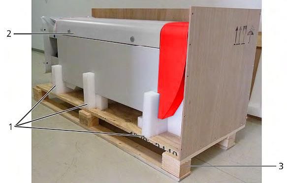
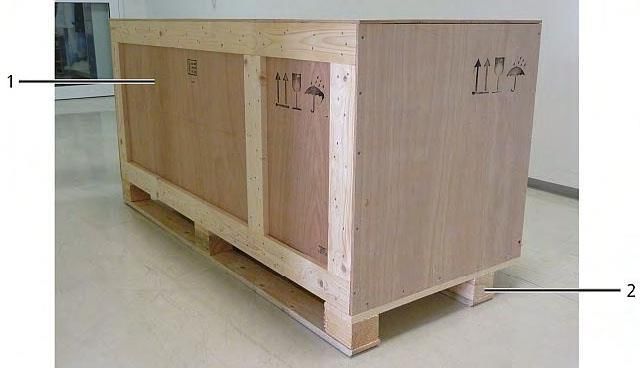
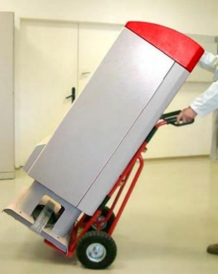
Operating Manual CHM 8k R2.0 / 02-2021 6.1.2 Installing on the foundation CAUTION The CHM 8k weighs 70 kg, heavy equipment may cause serious injury. Do not attempt to move the CHM 8k without adequate help At least two people are required to install the ceilometer Install the CHM 8k ceilometer as follows: Unload the CHM 8k from the transport equipment and set it down as close as possible to the place of installation. The position of the base of the instrument inside the transport crate is marked with “Boden / Base” on the crate. Figure 5 CHM 8k packed and in transport position (1: wooden crate, 2: pallet). Remove the packaging. Unscrew the side panels. Remove the side panels individually. Figure 6 The CHM 8k with Styrofoam or paper honeycomb packing pads. 1 Here: Polystyrene packaging 2 CHM 8k 3 Pallet Installation 16
Operating Manual CHM 8k R2.0 / 02-2021 Carefully lift the CHM 8k out of the polystyrene packaging or paper honeycomb packaging by hand, observing all safety regulations. (Lifting positions: Figure 7). Figure 7 Lifting positions and handle protection (edge protection profile). Onward transport options: To carry: Grasp the equipment in the openings marked with arrows (Figure 7). Hand truck: For greater distances to the concrete foundation (Figure 8). NOTICE When transporting with a hand truck, make sure that the CHM 8k is placed on the hand truck with the exterior door facing downwards (see Figure 8). A cushion (e.g. bubble wrap) should be placed between the CHM and the hand truck. Figure 8 Transport with hand truck. Position the CHM 8k in the installation position (vertical) on the concrete foundation. It is important to pay attention to the position of the exterior door in relation to the operator’s connection box (see Figure 4). Loosely pre-assemble the CHM 8k on the concrete foundation with the supplied washers and fixing screws (see Figure 9). Installation 17
Operating Manual CHM 8k R2.0 / 02-2021 Figure 9 Fixing elements. 1 Dowel S12 2 Leveling screw 5 mm (integrated into the base of the device) 3 Screw DIN 571-10 x 140-ZN 4 Washer ISO 7093-10.5-A2 5 Washer ISO 7093-10.5-KST/PA 6 Concrete foundation Vertically align the CHM 8k using the levelling screws integrated into the base of the device (with a spirit level: place on one side wall and on the front). Tools required: 22 mm spanner / wrench. Tighten the fixing screws. Tools required: 17 mm spanner / wrench. Remove the handle protection (edge protection profile) from above and secure in the base for the next transport. 6.2 Electrical installation NOTICE Incorrect installation may result in damage to the equipment. The electrical connection of the CHM 8k may only be carried out by a qualified electrician of OTT HydroMet Fellbach GmbH or another qualified electrician. Failure to comply will result in the loss of warranty and warranty claims. The operator must meet all the requirements for connecting the CHM 8k ceilometer in accordance with EN 61010-1, e.g., installation of a connection box. An overvoltage and lightning protection system is installed within the Ceilometer. If the customer needs to measure the isolation resistance, then it is allowed and needed to use 250V DC. The value of the isolation resistance must be above 1 MΩ. Figure 10 shows a schematic sketch of the electrical installation of the CHM 8k. The power supply (1) to the device must be connected via an external mains switch (2) which needs to be easily accessible to cut the power to the device when required. It must be marked as belonging to the CHM 8k and a pre-fuse 10A gG time-lag must be used only for 230VAC-devices. The connection box should be installed at a distance of < 3 m. An external lightning conductor (7) must be installed to protect the device from direct lightning strikes. All connections to the device must be made according to the respective country-specific regulations. Installation 18
Operating Manual CHM 8k R2.0 / 02-2021 Figure 10 Schematic sketch of the electrical installation. 1 Power supply (3-pole) 2 Mains switch and electric junction box 3 Data transfer cables: RS485 or LAN, 4 Data cable connection: RS485 or LAN 5 PC for remote access (via LAN/DSL; PC must not be local) 6 Ground connection ceilometer 7 Lightning conductor WARNING Touching live parts may result in electric shock, which will cause serious or fatal injury. Switch off the external circuit breaker before starting the installation and secure against reconnection. The electrical connections to the CHM 8k are specified in more detail in Figure 11. Connect the mains and data cables as shown in this figure. It is recommended to include external overvoltage protection in all connections to the device to prevent damage to the connection box. Internal lightning protection is provided in the device. The CHM 8k is connected via the following supplied cables: 1. 230 VAC supply cable (mains cable): color code: neutral conductor: blue, conductor: brown, protective conductor: green-yellow); standard length 10 m. OR 115 VAC supply cable (mains cable): color code: conductor black, neutral: white, protective conductor: green / green-yellow Installation 19
Operating Manual CHM 8k R2.0 / 02-2021

Figure 11 Electrical installation.

 2. Grounding cable 10 mm² (1-pin, green-yellow), standard length 2.6 m, for the grounding
 connection (see Figure 12). The grounding cable must be kept as short as possible.

 Figure 12 Grounding connection at pedestal of device.

Installation 20
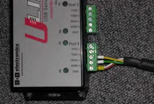
Operating Manual CHM 8k R2.0 / 02-2021

 3. Data cable (RS 485, 3 wire): A (-) conductor: yellow; B (+) conductor: green; RS485 - GND: white
 & brown; shielding as required: (see Figure 13); standard length 10 m.

 Figure 13 RS485 connection to transducer.

 4. Data cable (LAN): equipped with a standard RJ45 plug, for connection to a remote computer,
 hub or switch, standard lengths 5 or 10 m.

Installation 21
Operating Manual CHM 8k R2.0 / 02-2021 7 Commissioning and Decommissioning 7.1 Starting up with the RS485 connection Requirements: • The CHM 8k ceilometer must be installed correctly • Control cable (RS485), grounding cable and mains cable (115 VAC or 230 VAC) must be connected • A terminal program, e.g., HyperTerminal or Bray’s terminal, can be used under Windows for monitoring communication. It has to be configured for communication as follows: - Baud rate: 9,600 - Data bits: 8 - Parity: none - Stop bits: 1 - Flow control: none CAUTION After switching on the power supply, the CHM 8k emits Class 1M invisible laser radiation through the opening at the top of the sensor. When viewed with optical instruments, Class 1M radiation can lead to serious eye injuries. Never view the laser beam with optical instruments, especially binoculars Avoid looking directly into the laser beam After connecting the supply voltage, the CHM 8k will start up by itself. During the start-up process an internal self-check is done, e.g. the fans start for a few seconds. Communication with the device is possible within 1 minute. The CHM 8k will be fully operational after a temperature adjustment phase of varying length depending on outdoor temperature conditions. The time until measurement data are available in high quality, can be between 2 minutes (warm start) and one hour (cold start at -40 °C). The CHM 8k automatically sends out standard data telegrams when the start-up procedure has been completed. It is part of the default setup and might differ for user specific CHM 8k start settings. The automatic output every 15 s is helpful to check if the communication works correctly without entering any command. To change the start-up behavior like polling vs automode or the telegram that should be used at start see chapter 8 Communication via RS485 & Ethernet. Test commands for RS485 communication To test the communication, use the command (RS485Number = 16 (default value)): set:Transfermode=0 This command changes the settings from auto to polling mode. Testing in polling mode is helpful to avoid interruptions by automatically sent telegrams while typing. 9 telegram types are available: • Standard data telegram (short name: 1 or s) • Extended data telegram (short name: 2 or l) • Raw data telegram (short name: 3 or a) • User telegrams (short name: 4, 5, ..., 9) Section 8 describes the possible commands and their effects in detail. Some commands for functional testing required in routine operation or to setup the system in the beginning are listed in Table 3. Commissioning and Decommissioning 22
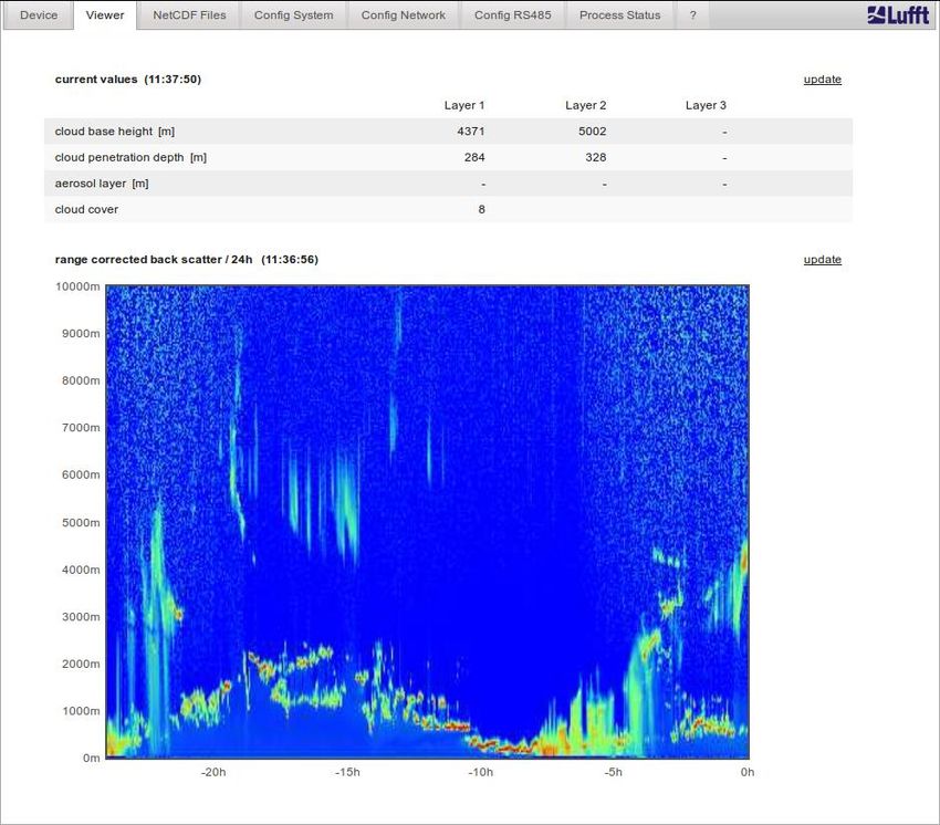
Operating Manual CHM 8k R2.0 / 02-2021

 Command Description Response (shortened)

 get16:L Output of extended data see 8.3.4
 telegram

 set16:RNO=14 Sets the RS485Number set 16:RNO=14
 from 16 to 14
 set16:Baud=4 Sets baud rate to 19,200 set 16:Baud=4

 set16:dt(s)=15 Sets logging time interval to set 16:dt(s)=15
 15 s
 get16:Lifetime(h) Readout of the laser get 16:Lifetime(h)
 operating hour counter

Table 3 Commands for functional testing (examples).

After completing the simple functional test on the CHM 8k:

 • Continue to operate in polling mode, or
 • Reset to automatic transmission mode

set:Transfermode=1

Comment: This command leads back to the automatic transmission mode of the standard telegram 1.

 Baud rate with raw data transmission
 The baud rate settings must be observed, especially in RS485 bus mode. If raw data
 transmission is required, each telegram can be 12 kB in size. To reduce the
 transmission time between two 15 s telegrams the baud rate must be set to at least
 19,200 baud.

7.2 Starting up with the LAN connection
In addition, or as an alternative to the RS485 connection, a LAN connection (Ethernet) can also be used.

Requirement: A connected LAN cable (see 6.2 Electrical installation) or LAN over DSL connection with
a DSL transmitter and receiver modem in between.

Configuration: 3 separate IP addresses are available for simultaneous communication:

 1. A preconfigured fixed service address to the device
 ➔ 192.168.100.101, subnet 255.255.255.0
 2. DHCP server assignment (requires a DHCP server)
 3. User address + subnet + gateway,
 see section 8.7 Communication via Ethernet web interface for the configuration with a LAN
 / WAN connection to the device and 8.2, if these values are configured with the RS485
 interface.

The service address (1) cannot be changed by the user. It is always available and can be used as a direct
connection between a laptop and the CHM 8k.
One of the 3 IP addresses can be entered into a web browser (see Figure 14) for communication with
the device. Figure 18 shows the "Config Network" tab in the Internet browser Firefox. Changing the user
IP address (3) requires superuser authorization in the device tab.

The superuser password is: 8k-MHC
The superuser password can be changed if necessary, see Figure 21.
The web interface was tested with the following web browsers:
 • Internet Explorer 8 or later
 • Firefox 3.6 or later

Commissioning and Decommissioning 23
Operating Manual CHM 8k R2.0 / 02-2021 • Google Chrome • Apple Safari In the DHCP network environment (2), the CHM 8k is configured automatically. The DHCP mode can be switched off. Figure 14 Firefox browser for a connection with the CHM 8k (shown here with fixed IP address). It is possible to use the RS485 connection and query the DHCP IP address by entering: get:IPD If available, the device transmits the DHCP address that can be used in a second step in a web browser to connect to the system via a LAN connection. The user IP address can be set or queried by the user via RS485, too, using the parameter IPS instead of IPD, e.g.: get:IPS set:IPS=xxx.xxx.xxx.xxx For further support regarding communication please contact OTT HydroMet Fellbach GmbH. 7.3 Shutdown Advanced users should carefully disconnect the device from the power supply with these steps: Users with superuser authorization should use the web interface: Log in as a superuser and press "SHUTDOWN SYSTEM" on the device tab RS485 users can enter the following command: set:SHT In both cases the Linux-based system is turned off and measurement data are stored on the local SD card. After the soft shut down the main power can be disconnected without the risk of data loss. To uninstall the CHM 8k and reinstall it at a different location, carry out the steps described in sections 6.1.2 Installing on the foundation and 6.2 Electrical installation in reverse order. 7.4 Disposal Disposal Notice Disposal of the CHM 8k Cloud Height Meter must be in accordance with national regulations. Electrical equipment marked with this symbol may not be disposed of in European domestic or public disposal systems. Return old or end-of-life equipment to the manufacturer for disposal at no charge to the user. Commissioning and Decommissioning 24
Operating Manual CHM 8k R2.0 / 02-2021

8 Communication via RS485 & Ethernet
The CHM 8k supports the interfaces RS485 (see section 8.2) and Ethernet (see section 8.7) for
communication with the device. Both offer the possibility of data transfer of the measured values and the
configuration of the device and can be used at the same time.
A web interface is part of the device for the communication via the Ethernet interface. Regardless of the
operating system, the ceilometer can be accessed through various web browsers.
The web interface can also be used to manually download the measured data stored in NetCDF daily
files on a built-in SD card (see section 8.4). Also implemented on the system is an AFD (ftp) service (see
section 8.8) which, for example, allows data in the form of 5-minute blocks of NetCDF files to be
transferred to an external FTP server.
RS485 communication requires a terminal program.

 Transmit and receive with RS485
 The RS485 interface does not allow simultaneous send and receive operation (half
 duplex mode). Accordingly, the interface is automatically switched internally. Hence,
 while receiving an automatically transmitted data telegram (see sections 8.3.3 to
 8.3.5), it is not possible to send other commands (as described in 8.1). The incoming
 start and end flags and indicate a current receive transmission.

8.1 List of configurable parameters
Table 4 lists the most important settings. These are explained in the following sections. To prevent
unwanted effects on the functioning of the device, some options can only be set in service mode (RS485)
or in super user or service user mode (Ethernet), such as the device name. Table 5 shows a list of other
parameters (read-only properties). These parameters are stored in part on the EEPROM on the
measuring unit and affect data evaluation and the basic system settings. The tables contain the
permissible value range for each parameter and the default value on delivery of the device. They also
contain an indication when the service mode is required or when the parameter availability is different
between RS485 and web-interface.

 Parameter Short Default Range / short description
 cmdRS485 value
 AfdMode* AFD 0 0; 1, switch on (s)ftp data transfer

 Altitude(m) ALT 0 0 – 9999, unit is always in meters!

 ApdControlMode* ACM 2 0 – 2, APD mode, change only if function is
 known in detail

 Azimuth AZT 0 0-360 degrees (x 100)Web
 (e.g. 12.25RS485 and 1225Web)

 Baud BAU 3 2 – 7 (4,800 – 115,200 baud)

 BaudAfterError* BAE 3 2 – 7 (4,800 – 115,200 baud)

 BlowerMode BLM 0 0–4

 ChmTest* CHT 0 0; 1

 CloudDetectionMode CDM 3 0 – 3, switch between variants of algorithm
 (Bit 0 = HLC, Bit 1 = BLC)

 Comment COM Comment; also stored in the NetCDF file

 Comment 1RS485 CM1 Additional comment field (31 characters)

 Comment 2RS485 CM2 Additional comment field (31 characters)

 Comment 3RS485 CM3 Additional comment field (31 characters)

 Comment 4RS485 CM4 Additional comment field (31 characters)

Communication via RS485 & Ethernet 25
Operating Manual CHM 8k R2.0 / 02-2021

 Parameter Short Default Range / short description
 cmdRS485 value
 Comment 5RS485 CM5 Additional comment field (31 characters)

 Comment 6RS485 CM6 Additional comment field (31 characters)

 Comment 7RS485 CM7 Additional comment field (31 characters)

 DateTime UTC Time in the format
 DD.mm.YYYY;HH:MM:SS RS485
 and MMDDHHmmYYYY Web (see Figure 21)

 DeviceName* DVN CHMyyxxxx CHM + serial number of the device

 DeviceType* DVT 0 Switch NetCDF format

 DHCPMode DHM 1 0;1 switch DHCP mode on / off

 DNSServer DNS Set / queries IP address of name server

 dt(s)RS485 DTS 15 Logging and reporting time: 5 – 600 s
 LoggingTimeWeb

 Gateway GAT 0.0.0.0 Set / request the static gateway address

 HardwareVersion* HWV Device-dependent, see Table 26

 HttpPort HPT 80 Specifies http port to access the web interface
 of the ceilometer

 IgnoreChars* ICH 06 8-bit ASCII codes

 Institution INS NN Institution (text)

 IPaddress IPS 0.0.0.0 Set / request the static IP address

 LanPort LPT 11000 Port for telegram transmission via Ethernet

 LanTelegramNumber LTN 2 Telegram format for Ethernet transmission (1
 – 9), see section 8.3

 LanTransferMode LTM 1 Communication mode for telegram
 transmission via Ethernet
 (0 = polling; 1 = automatic sending)
 LaserMode* LSM 1 Switch laser on / off

 LaserFrequenceMode* LFM* 0 0 – 13, set the laser repetition rate

 Latitude LAT 0 -90 to +90 degrees (x 106)Web
 (e.g. 52.430210RS485 and 52430210Web)
 + is degrees North
 Layer NOL 3 1 – 9, number of cloud layers

 Location LOC NN Alphanumeric string (max. 31 characters,
 \ / : * ? " < > | _ # % not allowed)
 Longitude LON 0 -180 to +180 degrees (x 106)Web
 (e.g. 13.524735RS485 and 13524735Web)
 + is degrees East
 MaxCrosstalkChars* MCC 5 0 – 1024

Communication via RS485 & Ethernet 26
Operating Manual CHM 8k R2.0 / 02-2021

 Parameter Short Default Range / short description
 cmdRS485 value
 NetcdfMode NCM 1 Cannot be changed for the CHM8k

 NetMask NMA 0.0.0.0 Set / request the static Netmask address

 NtpMode NTM 1 0; 1 switch ntpd on / off

 NtpServer NTS 0.0.0.0 Set / request the NTP time server address

 PeltierMode* PTM 1 0; 1

 RangeEnd RAE 10000 Last range value in a NetCDF file

 RangeHRDim RHD 32 Number of data points in the high-resolution
 data vector
 RangeResolution RAR 3 Number of 5 m range intervals averaged for
 the NetCDF data vector
 RangeStart RAS 5 First range value in a NetCDF file

 Reset RST 0 0; 1 restart of the CHM (see 8.2.4)

 ResetPassword* RSP 0 0; 1; reset the super user password

 ResetSettings RSG 0 0; 1 reset to the factory settings, (see 8.2.4);
 Web interface: “set to factory setting”

 RestartNetwork RSN 0 0; 1 writes the new settings in the
 configuration file and restarts the network

 RS485Number RNO 16 0 – 99 (used with RS485)

 ServiceModeRS485 SMO 0 0; 1 switches to the service mode to change
 “critical” values

 Shutdown SHT 0; 1 shuts down the CHM system

 Standby STB 0 0; 1 Standby mode with standby telegram to
 reduce power consumption

 SystemStatusMode SSM 1 0; 1 the escalated status code will be used in
 the telegram if set to 1

 TimeOutRs485(s)* TOR 30 5 – 3600

 TimeZoneOffsetHours TZH 0 -12 .... 12 hours, e.g. CET is +1, used to
 control the window ventilation

 TransferMode TMO 1 0 – 9, see section 8.3

 TransferModeAfterError* TME 1 0–9

 ToggleMainboardFan* TMF 0 0; 1
 0 = automatically (depending on temperature)
 1 = on for 10 minutes, then “0” again

 UAPD* Device-dependent in mV (e.g. 172000)

 Unit(m/ft) UNT m m, ft

 UseAltitude UAL 0 0; 1

Communication via RS485 & Ethernet 27
Operating Manual CHM 8k R2.0 / 02-2021

 Parameter Short Default Range / short description
 cmdRS485 value
 WIGOSStationID WSI Set / query the WIGOS station identifier

 WMOStationCode WSC Set / query the WMO station code

 Zenith ZET 0 0 - 90 degrees (x 100)Web
 (e.g. 10.25RS485 and 1025Web)
 0° is vertical
Table 4 List of configurable parameters,
 * can be set in service mode,
 Web
 format for web interface, or only in web interface available
 RS485
 format for RS458, or only for RS485 available

 Parameter Short Default Description
 cmdRS485 value

 APDBreakdown UBR Device-dependent (e.g. 172000 mV)

 ApdTempGradient TCO Device-dependent (e.g. 1090 mV/K)

 IPDhcp IPD IP address DHCP

 LifeTime(h) LIT Number of hours that the laser is in operation

 ParametersRS485 Prints a list of all parameters that are available
 in the RS485 mode

 SerLOM LOM TUByyxxxx Serial number of the measuring unit (LOM)

 SystemLifeTime(h) SLT Total number of all operating hours of the CHM
 system

 TBCalibration TBC Scaling factor compared to reference

 VersionFirmware VFI Firmware version
 (data processing and handling)

 VersionFPGA VFP Firmware FPGA

 VersionLinux VLI Operating system version
Table 5 List of read-only parameters, accessible via the RS485 interface;
 RS485
 only for RS485 available

Explanatory notes to Table 4

AFDMode: Switch on / off the extended file distribution system via LAN / WAN / DSL, see
http://www.dwd.de/AFD/ for more information or section 8.8 AFD mode.

Altitude(m): Specification of the height of the location above sea level in meters. In NetCDF files, the
parameter CHO (Cloud Base Offset) is used. It logically combines the variables Altitude and UseAltitude.

Azimuth: Specification of the horizontal angle in degrees.

Baud: Change baud rate (see 8.2.3 Changing the baud rate).

BaudAfterError: Default baud rate after communication error (see 8.2.3 Changing the baud rate).

BlowerMode: Used to test the window fans and switch to different operating modes. Mode 2: “rest at
night” works only correctly if the parameter TimeZoneOffsetHours is set correctly, too. 0 = hourly check

Communication via RS485 & Ethernet 28
You can also read