Design, Analysis, Control and Manufacturing of a Head Massaging Machine
←
→
Page content transcription
If your browser does not render page correctly, please read the page content below
IOP Conference Series: Materials Science and Engineering

PAPER • OPEN ACCESS

Design, Analysis, Control and Manufacturing of a Head Massaging
Machine
To cite this article: Aman Chaure and E Rajkumar 2021 IOP Conf. Ser.: Mater. Sci. Eng. 1123 012013

View the article online for updates and enhancements.

                              This content was downloaded from IP address 46.4.80.155 on 04/07/2021 at 02:51
International Conference on Design, Automation, and Control (ICDAC 2020)                                                 IOP Publishing
IOP Conf. Series: Materials Science and Engineering              1123 (2021) 012013           doi:10.1088/1757-899X/1123/1/012013

       Design, Analysis, Control and Manufacturing of a Head
       Massaging Machine
                          1Aman Chaure, 2Rajkumar.E

                          1Under Graduate student, SMEC, VIT, Vellore, India,
                          amanchaure@gmail.com,
                          2Associate professor, Department of Design and Automation, SMEC, VIT,
                          Vellore, India
                          rajkumar.e@vit.ac.in

                          Abstract. Nowadays, a lot of people are suffering from unexpected Headaches at odd hours of
                          the day due to their hectic schedule and busy lifestyle. Many devices for massage therapy have
                          already been introduced in the market for the same but none of them are actually worth the price
                          as they fail to deliver the quick necessary relief. For overcoming this problem, we have come up
                          with a new design for head massaging which mainly works on the ideal concept of massage
                          therapy by pressing the optimum pressure points located at the extremes of the forehead. The
                          novelty of this paper lies in the mechanism involved that will help us to achieve the desired
                          output. We will be presenting the complete design, control and manufacturing for the product by
                          a series of simulations which will includes Linear Static Stress analysis for evaluating the
                          strength of the design which can produce the right amount of force, Vibrational/Modal Frequency
                          response for analysing the stability while functioning, Fatigue Test for evaluating the maximum
                          stress the design can bear for a good life and finally comes the Thermal Analysis for evaluating
                          the heat dissipation from the electronics. The Computer Aided Design will be developed on
                          SOLIDWORKS Software and the Finite Element Simulations will be conducted on ANSYS for
                          optimization. Some post simulations will also be conducted such as drop test for evaluating the
                          chances of sudden failure under the circumstances of impact loading. At last there will be a
                          complete manufacturing planning for the entire design along with its DFMA planning.
                          Keywords. Optimization, Computer Aided Design, Finite Element Simulations
       I. Introduction

       Massage therapy the most important part of physiotherapy), is one of the most useful way of relieving
       ourselves from mental stress. For this a head massaging machining has been designed with actuators in
       the most promising location for the quick relief operation. A rocker arm mechanism has been modified
       and designed to serve the purpose. The push rod of the rocker arm along with the cam shaft is replaced
       with the Linear actuators for serving the same purpose. The effective output of work maintained by the
       designed control system for optimum functionality

      The point at which the
         proposed designed
      machine focuses over.
                                                       .

                                 Figure 1. The point of Action of Force for massage

              Content from this work may be used under the terms of the Creative Commons Attribution 3.0 licence. Any further distribution
              of this work must maintain attribution to the author(s) and the title of the work, journal citation and DOI.
Published under licence by IOP Publishing Ltd                          1
International Conference on Design, Automation, and Control (ICDAC 2020)                                              IOP Publishing
IOP Conf. Series: Materials Science and Engineering           1123 (2021) 012013            doi:10.1088/1757-899X/1123/1/012013

      2. Literature Review

     Juvenile Rheumatoid Arthritis: Benefits from Massage Theraphy [1], this paper focuses on the effect of head
     massaging over the children for decrease in the stress levels and the anxiety, Head massage machine, a currently
     existing Patent in the same field [2]. Hand type electric massage machine, another consisting patent [3], The
     short‐term effects of myofascial trigger point massage therapy on cardiac autonomic tone in healthy subjects [4],
     this paper contains the study of point massage therapy for stress relieving effects over the body, The effect of
     massage in patients with chronic tension headache [5].

     3. Problem description

     A lot of designs are currently existing under the head massaging division or category. But our design mainly
     focuses over the two points each on either side of the forehead serving only a single action but having the
     greatest effect of its little functionality. The main problem is that all the currently existing designs are focusing
     over multiple points of the head and fore head but are not capable of providing quick relief by the same. For
     this problem I have come up with a very simple solution by focusing all the energy of a small device over the
     most promising location of the head.

     4. Methodology

     The methodology for out design is quite simplistic. We have started with rough design for the same product
     and then by analysing the same with Triz contradiction matrix followed by a 2nd design. Then Simulating the
     same with Static Analysis in SOLIDWORKS Software for analysing its functionality. The detailed study is
     giving in the steps followed here.
     Step 1: 1st conceptual Design, containing the details just about the basic idea.
     Step 2: Triz Contradiction Matrix with results, for improving the design on the basis of Triz concepts.
     Step 3: 2nd iterative design with the changes proposed by the Triz matrix, giving us the improves design.
     Step 4: Analysing the same design for its functionality in SOLIDWORKS Simulation package.

     Step 5: The manufacturing planning for the same using FLASHPRINT Software for printing the structure in
     a single go.
     Step 6: The Control Planning for the same with Arduino UNO and a Linear Motor.

                                           TRIZ Contradiction Matrix

      S No.                           20               21              24             27            40              41
              Improving                                                                             Harmful Effects
              Factors\Worsening                                        Function       Loss       of Generated   by Manufacturabilit
              Factors:                Stress           Stability       Efficiency     Energy        System          y
              weight    of   Moving
      1       Object                  28, 31, 40, 35   35, 1, 30, 39 1, 2, 28, 3      19, 6, 3, 10 5, 24, 27, 21     1, 5, 36, 25

              weight of stationary
      2       Object                35, 31, 8, 40      15, 5, 17, 30 35, 31, 7, 3     28, 35, 7, 31 17, 37, 31, 3    35, 8, 9, 1
              Duration of Action of                                                   10, 24, 35,
      12      Moving Object         35, 3, 17, 14      35, 24, 40, 13 13, 1, 19, 12   23            21, 28, 15, 24   35, 4, 10, 3

                                                                   2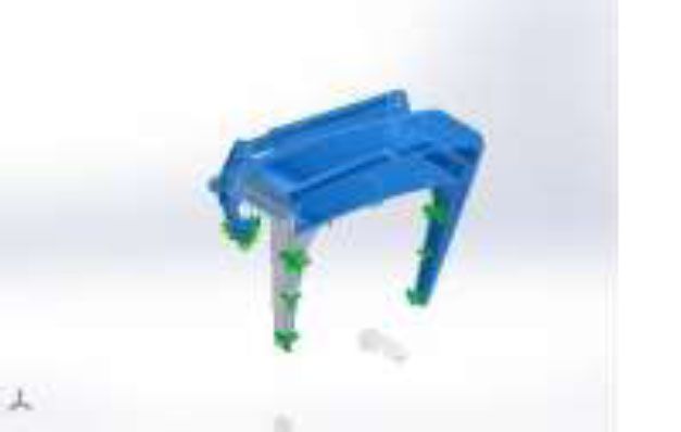
International Conference on Design, Automation, and Control (ICDAC 2020)                               IOP Publishing
IOP Conf. Series: Materials Science and Engineering     1123 (2021) 012013      doi:10.1088/1757-899X/1123/1/012013

      15   Force/Torque         35, 14, 9, 3      35, 10, 24, 19, 35, 6, 13 19, 15, 2, 10, 35, 40, 22 15, 18, 35, 6
           Energy used in                                                   19, 15,
      16 the moving object 19, 35, 5, 9           13, 19, 24, 2, 13, 28, 12 12,        2, 10, 3, 22   28, 5, 30, 10
     Outcomes of the Triz Matrix:

     • Principle 3. Local quality
     • A. Change an object's structure from uniform to non-uniform, change an external environment
     • B. Make each part of an object function in conditions most suitable for its operation.
     • C. Make each part of an object fulfill a different and useful function.
     • Principle 5. Merging
     • A. Bring closer together (or merge) identical or similar objects, assemble identical or similar parts toperform
     parallel operations.
     • B. Make operations contiguous or parallel; bring them together in time.
     • Principle 6. Universality
     • A. Make a part or object perform multiple functions; eliminate the need for other parts.

     5. Modelling
     The isometric View for the Model is shown from both Front and Back Side in the figures 1 to
     2. Then comes the orthographic views from figure 3 to figure 4. In these figures the dimensional views are
     presented along with all the dimensions in mm.

                             Figure 2. Isometric view of the Head Massaging Machine.

                                                           3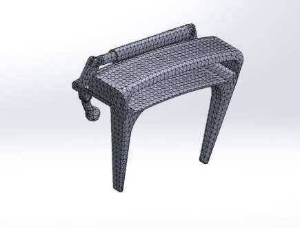
International Conference on Design, Automation, and Control (ICDAC 2020)                            IOP Publishing
IOP Conf. Series: Materials Science and Engineering    1123 (2021) 012013      doi:10.1088/1757-899X/1123/1/012013

                             Figure 3. Isometric view of the Head Massaging Machine.

                                  Figure 4. Orthographic view of the top head part.

                                                          4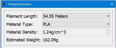
International Conference on Design, Automation, and Control (ICDAC 2020)                               IOP Publishing
IOP Conf. Series: Materials Science and Engineering     1123 (2021) 012013        doi:10.1088/1757-899X/1123/1/012013

                              Figure 5. Orthographic view of the top head part.

     6. Experimentation
     The Finite Element Analysis was done to carry out the Static Simulation to Check the Stress and
     Deformation and The Strain over the Structure under the Reaction forces over the Structure itself. The
     Factor of Safety was also Calculated for the same for verifying the overall safety limits for the
     Functionality.

                                                Table 1. Study Properties
        Study name                                        Static 1
        Analysis type                                     Static
        Mesh type                                         Solid Mesh
        Thermal Effect:                                   On
        Thermal option                                    Include temperature loads
        Zero strain temperature                           298 Kelvin
        Include fluid pressure effects from               Off
        SOLIDWORKS Flow Simulation
        Solver type                                       FFEPlus
        Inplane Effect:                                   Off
        Soft Spring:                                      Off
        Inertial Relief:                                  Off
        Incompatible bonding options                      Automatic
        Large displacement                                Off
        Compute free body forces                          On
        Friction                                          Off
        Use Adaptive Method:                              Off

                                                           5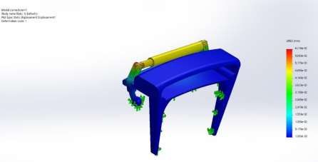
International Conference on Design, Automation, and Control (ICDAC 2020)                                   IOP Publishing
    IOP Conf. Series: Materials Science and Engineering        1123 (2021) 012013       doi:10.1088/1757-899X/1123/1/012013

             Result folder                                             SOLIDWORKS document
                                                                  (C:\Users\AMAN CHAURE\Desktop\books to
                                                                  complete\New product development)

          7. Results and Discussions

            Units
            Unit system:                                              SI (MKS)
             Length/Displacement                                      mm
             Temperature                                              Kelvin
             Angular velocity                                         Rad/sec
             Pressure/Stress                                          N/m^2

Material Properties
        Model Reference                                   Propertie                                 Component

                             Name: Nylon 6/10                                             SolidBody 1(Boss-Extrude1)(13
                             Model type: Linear Elastic Isotropic                         mm pin-1), SolidBody 1(Boss-
                             Default failure criterion: Max von Mises                     Extrude1)(13    mm      pin-2),
                             Stress                                                       SolidBody 1(Boss-Extrude1)(28
                             Yield strength: 1.39043e+08 N/m^2                            mm pin-1), SolidBody 1(Boss-
                             Tensile strength: 1.42559e+08 N/m^2
                                                                                          Extrude1)(28    mm      pin-2),
                             Elastic modulus: 8.3e+09 N/m^2
                                                                                          SolidBody 1(Scale1)(cylinder-
                             Poisson's ratio: 0.28
                             Mass density: 1,400 kg/m^3                                   1),
                             Shear modulus: 3.2e+09 N/m^2                                 SolidBody              1(Cut-
                               Th       l        i     ffi i t 3 05 /K l i                Extrude7)(head sub part
 Figure 6: Model with Constraints

          Resultant Forces
          Reaction forces
           Selection set Units                Sum X               Sum Y             Sum Z          Resultant
           Entire Model N                     1.04606e-05         -15.4034          3.45294        15.7856
          Reaction Moments
            Selection set    Units            Sum X              Sum Y           Sum Z            Resultant
            Entire Model     N.m              0                  0               0                0

                                                                  6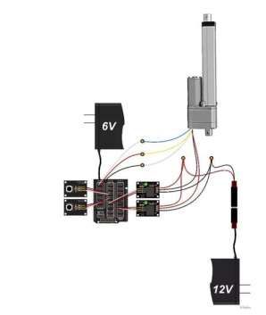
International Conference on Design, Automation, and Control (ICDAC 2020)                             IOP Publishing
  IOP Conf. Series: Materials Science and Engineering    1123 (2021) 012013       doi:10.1088/1757-899X/1123/1/012013

Name                         Type                                    Min                       Max
Displacement1                URES: Resultant Displacement            0.000e+00 mm              6.210e-02 mm
                                                                     Node: 3046                Node: 3114

                                            Figure 7. Displacement Contour

  Name                        Type                                Min                        Max
  Strain1                     ESTRN: Equivalent Strain            7.819e-11                  2.921e-04
                                                                  Element: 9115              Element: 2417

                                                Figure 8. Strain Contour

Name                                    Type
Displacement1{1}                        Deformed shape

                                                  Figure 9. Deforment

                                                            7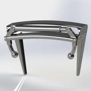
International Conference on Design, Automation, and Control (ICDAC 2020) IOP Publishing
IOP Conf. Series: Materials Science and Engineering 1123 (2021) 012013 doi:10.1088/1757-899X/1123/1/012013
Figure 10. Meshing with Triangular elements.
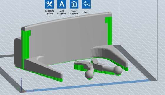
8. Manufacturing Simulation
The recent Trends in the market are the advancements in the additive manufacturing. With the ease of
Manufacturing, additive manufacturing plays a very important role in the new Product Development.
Thereby we will be using the 3D printing with Flash Forge Guider II printer for Additively
Manufacturing the product with Nylon 6 material. The hinges and pins of Standard sizes can be used
for assembly purpose if not preferred for printing.
Figure 11. 3d Printing
Simulation
8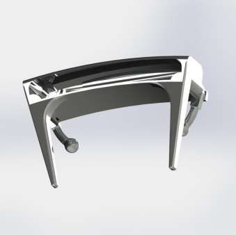
International Conference on Design, Automation, and Control (ICDAC 2020)                           IOP Publishing
IOP Conf. Series: Materials Science and Engineering    1123 (2021) 012013     doi:10.1088/1757-899X/1123/1/012013

      Time required for Printing with Flash Forge Guider Printer is Calculated to be around 27 Hours and its
      analysis can be seen in the below photograph & The Preferred Configuration for Printing Parameters is
      given below:

                         Figure 12. 3d Printing Time Calculations for Flash Forge Guider 2
                                                     Printer.

                     Figure 13. Parameters for Printing Nylon 6/10 With Flash Forge Guider 2
                                                      printer.

                                                          9
International Conference on Design, Automation, and Control (ICDAC 2020) IOP Publishing
IOP Conf. Series: Materials Science and Engineering 1123 (2021) 012013 doi:10.1088/1757-899X/1123/1/012013
Figure 14. Weight Estimation for the Printed
Parts
9. Control System
The Control system has been designed to give pulse load to the rocker arms of the product giving it a
too & fro motion along with some delay in the between two cycles. This Control System is powered by
an Arduino UNO & Genuino UNO,
Figure 15. The image for the control system [8], from an open source
document.
10. Prototype Development
The Prototype development will be done in future for this product after filing a design patent. The same
manufacturing planning will be done for making a functional prototype for the same.
10International Conference on Design, Automation, and Control (ICDAC 2020) IOP Publishing
IOP Conf. Series: Materials Science and Engineering 1123 (2021) 012013 doi:10.1088/1757-899X/1123/1/012013
11. Conclusions
By this project, we can conclude that after this planning the machine is ready for the manufacturing and
testing in the authorization of a Physician. After testing in the real time and by the affiliation of a doctor,
the machine will be ready for production on a large scale.
References
[1] http://www.goodfellow.com/E/Polyamide-Nylon-6.html
[2]http://www.matweb.com/search/datasheet.aspx?MatGUID=8d78f3cfcb6f49d595896ce6ce6a2ef1&
ckck=1
[3] http://www.regner.es/product/ra-47x-high-speed-linear-actuator-with-feedback/
[4] https://electronicsforu.com/electronics-projects/controlling-linear-actuator-arduino
[5]https://www.hackster.io/robotgeek-projects-team/control-a-large-linear-actuator-with-arduino-
8a3953
[6] https://help.solidworks.com/2018/english/SolidWorks/cworks/t_Performing_Static_Analysis.htm
11You can also read