Installation and Operating Instructions Roth Stainless Steel Manifold Line - Living full of energy
←
→
Page content transcription
If your browser does not render page correctly, please read the page content below
Installation and
Operating Instructions

Roth Stainless Steel
Manifold Line
V.8.2020

                         Living full of energy
Roth Industries, Inc info@roth-usa.com
PO Box 245 www.roth-america.com
Syracuse, NY 13211 888-266-7684
Stainless Steel Manifold System Installation and Operation Manual
Product Cautions
Prior to starting work, the installer must read, understand and heed these installation and operating instructions.
The manifolds may only be installed, adjusted and maintained by trained contractors.Trainees may only work on
the product under the supervision of an experienced person. Only if the above instructions have been adhered to
will Roth Industries, Inc. accept any liability in line with statuatory provisions. Every instruction contained in these
installation and operating instructions is to be heeded when using the manifolds.
Intended Use
The manifolds are used for distributing and regulating the volume of flow in low temperature heating and cooling
systems. The manifolds will operate more efficiently and with greater longevity with the use of high quality fluid
with a low concentration of the minerals that create hard water. In the case of systems using heating fluid which
contains corrosive particles and other contaminants, dirt traps or filters with a mesh size of no more than 0.8 mm
(.032”, 800 micron) should be installed in order to protect the measuring and control devices.
The maximum permissible continuous operating pressure is 145 psi @ 176°F (10 bar @ 80°C). During the
pressure test, the return control valves must be closed. Using the manifolds for any purpose other that set out
in these instructions constitutes improper use. Roth Industries, Inc. accepts no liability for damage resulting from
improper use of it’s manifolds.
For safety and guarantee reasons, no conversion or modification is permitted.
Roth Industries, Inc. accepts no liability if connections and accessories made by other manufacturers are used.
2Roth Industries, Inc info@roth-usa.com
PO Box 245 www.roth-america.com
Syracuse, NY 13211 888-266-7684
Stainless Steel Manifold System Installation and Operation Manual
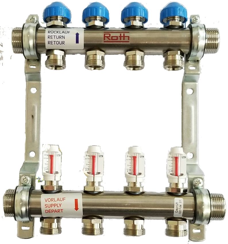
Product description
• Constructed of “Eco” friendly, non-polished stainless steel
• Available in 1” and 1 1/4” trunk sizes, 2 - 12 loop connections
• Sets include:
Straight isolation ball valves on trunk supply and return connections 1
Fill/drain/vent tees 2
Manual air vents 3
Fill/drain vent with 3/4” garden hose thread 4
1/4 Turn valve 5
Temperature gauges on supply and return isolation ball valves 6
Steel mounting brackets with rubber isolators 7
Flowmeters on supply manifold outlets with 0 - 2gpm scale 8
Flow regulator valves with manual multi-turn operators on return manifold inlets 9
Flow adjustment key 10
• Isolation ball valves and fill/drain/vent tees can be connected on either end of the
supply/return trunks
• 3/4” Euroconical compression fittings 11 used to attach tubing to manifold inlets/outlets (sold separately)
• Circuits not used can be shut off and protected with a loop cap 12 (sold separately)
7 9 7
3
2
p
5
Rücklauf / return
o n
°F PERT-AL-PERT PERT
6
PEX-AL-PEX PEX
1 11 4
10
1 8
3
2
p
Vorlauf / supply 5
o°F n
6
12 4
3Roth Industries, Inc info@roth-usa.com
PO Box 245 www.roth-america.com
Syracuse, NY 13211 888-266-7684
Stainless Steel Manifold System Installation and Operation Manual
Unpacking, inspection and assembly
Inspection
Inspect package upon receipt to ensure all contents are included and for damage
during shipping
Package contents
Supply and return manifold trunks attached to support brackets
Supply manifold includes flowmeters
Return manifold includes flow control valves w/ blue covers
Supply straight isolation ball valve - red - 1” or 1 1/4” (FPT)
Return straight isolation ball valve - blue - 1” or 1 1/4” (FPT)
End tee with manual air vent and fill/drain valve (2)
Temperature gauges (2)
Loop labels
Installation and Operation Manual
Assembly
Attach red handled isolation ball valve on the supply manifold trunk with flowmeters*
Attach blue handled isolation ball valve on the return manifold trunk with flow control valves*
Attach end tee to opposite end of each manifold trunk*
* Can be attached to either end of the manifold trunk
Insert temperature gauges into the isolation ball valves
Accessories (ordered and sold separately)
Description Part No.
Loop Actuator 24V 4-wire 2340055354
Automatic Air Vent 2315021004
Differential Pressure Bypass Valve -1” 2315021005
Manifold Extension Fittings 1” 2315021006
Loop Cap - 3/4” w/ Gasket 2315021007
Trunk Cap - 1” 2315021008
Trunk Cap - 1 1/4” 2315021009
Manifold Trunk Coupling - 1” 2315021010
Manifold Trunk Coupling - 1 1/4” 2315021011
4Roth Industries, Inc info@roth-usa.com
PO Box 245 www.roth-america.com
Syracuse, NY 13211 888-266-7684
Stainless Steel Manifold System Installation and Operation Manual
Dimensions
Length (L1) Length (L2)
Part No. Description
Inches mm Inches mm
2315020002 1” Stainless Steel Manifold Set 2 Loops 6.3 160 11 279
2315020003 1” Stainless Steel Manifold Set 3 Loops 8.3 210 13 329
)
2315020004 1” Stainless Steel Manifold Set 4 Loops 10.3 260 15 379
2315020005 1” Stainless Steel Manifold Set 5 Loops 12.2 310 17 429
2315020006 1” Stainless Steel Manifold Set 6 Loops 14.2 360 19 479
2315020007 1” Stainless Steel Manifold Set 7 Loops 16.2 410 21 529
8.27”
2315020008 1” Stainless Steel Manifold Set 8 Loops 18.1 460 23 579
2315020009 1” Stainless Steel Manifold Set 9 Loops 20.1 510 25 629
2315020010 1” Stainless Steel Manifold Set 10 Loops 22 560 27 679
2315020011 1” Stainless Steel Manifold Set 11 Loops 24 610 29 729
)
2315020012 1” Stainless Steel Manifold Set 12 Loops 26 660 31 779
2315020103 1 1/4” Stainless Steel Manifold Set 3 Loops 8.3 210 13 329
2.44”
1.97” 2.24” 2315020104 1 1/4” Stainless Steel Manifold Set 4 Loops 10.3 260 15 379
L1
2315020105 1 1/4” Stainless Steel Manifold Set 5 Loops 12.2 310 17 429
L2
2315020106 1 1/4” Stainless Steel Manifold Set 6 Loops 14.2 360 19 479
2315020107 1 1/4” Stainless Steel Manifold Set 7 Loops 16.2 410 21 529
2315020108 1 1/4” Stainless Steel Manifold Set 8 Loops 18.1 460 23 579
2315020109 1 1/4” Stainless Steel Manifold Set 9 Loops 20.1 510 25 629
2315020110 1 1/4” Stainless Steel Manifold Set 10 Loops 22 560 27 679
Dimension 1” 1 1/4” 2315020111 1 1/4” Stainless Steel Manifold Set 11 Loops 24 610 29 729
2315020112 1 1/4” Stainless Steel Manifold Set 12 Loops 26 660 31 779
T1
T1 (inch) 1.54 1.69
T1 (mm) 39 43
H T2 (inch) 2.52 2.68 Part # Description
T2 (mm) 64 68 PE-RT/PEX Fittings
D (inch) 3.39 3.7 2315021000 Manifold Tubing Fitting Assembly - 3/8” pkg of 10
D (mm) 86 94 2315021001 Manifold Tubing Fitting Assembly - 1/2” pkg of 10
2315021002 Manifold Tubing Fitting Assembly - 5/8” pkg of 10
H (inch) 11.5 11.9
2315021003 Manifold Tubing Fitting Assembly - 3/4” pkg of 2
H (mm) 292 303
Alu-Laser Plus Fittings*
2347131300 Manifold Tubing Fitting Assembly - 3/8” pkg of 10
T2
D
2347002331 Manifold Tubing Fitting Assembly - 1/2” pkg of 10
2347002332 Manifold Tubing Fitting Assembly - 5/8” pkg of 10
* - Brass fittings
Specifications
Parameter Value
Maximum Operating Temperature 176°F (80°C)
Minimum Operating Temperature 14°F (-10°C)
Maximum Operating Pressure 87 psi (6 bar)
Recommended Test Pressure (24 hr.) 87 psi (6 bar)
Temperature Gauge Range 32°F - 212°F (0°C - 100°C)
Flowmeter Range 0 - 2 gpm (0 - 7.5 lpm)
5Roth Industries, Inc info@roth-usa.com
PO Box 245 www.roth-america.com
Syracuse, NY 13211 888-266-7684
Stainless Steel Manifold System Installation and Operation Manual
Mounting
Location Guidelines
• The manifold system must be accessible for future inspection and maintenance.
• The supply/return and loop tubing should have an unobstructed approach and any bend radius must be
large enough to prevent kinking.
• Manifold systems should not be located in flood prone areas or exposed to the elements.
• Avoid exposing tubing to direct sunlight, even through a door or window. Long term exposure to UV rays
will cause the tubing to deteriorate.
• If manifold systems are located in an unconditioned space, appropriate measure must be taken to
prevent damage from freezing.
• Manifold must be level/plumb depending on mounting orientation.
Orientation
The RSS manifold set can be mounted in any position, however the following conditions may occur when the
manifolds are mounted in positions other than the upright position (loop tubing approaching from the bottom):
• Upside down (loop tubing approacing from the top)
• Dirt may accumulate in the flow meters over time. This will not have any effect on the flow rate
but may cause flow indicators to give false readings or stop working altogether.
• The flow meters will indicate flow, however they will lose some of their precision. The flowmeters
may indicate up to 20% less than actual flow.
• The manual air vents must be inverted to operate as intended.
• Vertical position ((loop tubing approaching from either side)
• Dirt may accumulate in the flow indicators with the same effect as above.
• The flow meters will indicate flow, however they will lose some ot their precision. The flowmeters
may indicate up to 20% less than actual flow.
• The manual air vent will operate as intended if it is located at the top of the manifold
Notification: Conditions above do not qualify for warranty replacement.
Attachment
• There are four mounting holes in the bracket set for attaching the manifold set using the appropriate
fasteners for the mounting surface material.
• When using a manifold cabinet, attach the manifold to the C profile rails using the supplied bolts. Refer to
manifold cabinet instructions for further information.
6Roth Industries, Inc info@roth-usa.com
PO Box 245 www.roth-america.com
Syracuse, NY 13211 888-266-7684
Stainless Steel Manifold System Installation and Operation Manual
Pipe connections
Manifold trunk connections
• The manifold trunks each have a 1” or 1 1/4” male BSPP thread for attaching the ball valve assemblies
and flush/fill and vent tees, with flat jonts. The union nuts on the assemblies are to be tightened with a
38 mm wrench to 26 - 33 ft. lbs. (35-45Nm). Do not use pipe thread sealant.
Supply and return connections
• The ball valve assemblies each have a 1” or 1 1/4” FNPT thread. Threaded adaptors should be fastened
to the ball valves using a pipe thread sealant.
Tubing Connections
Instructions for 3/8”, 1/2” & 5/8” fitting assemblies:
• Cut tubing at a right angle and clean edges of any burrs.
• If attachiing PERT-AL-PERT or PEX-AL-PEX be sure to bevel inside edge
90°
with a reaming tool.
• Push compression nut (2) and split ring (3) over the tubing (1).
• Insert euroconical fitting (4) into the tubing all the way to the backstop.
PERT-AL-PERT PERT
• Push the euroconical fitting into the threaded manifold fitting (6) until it seats.
PEX-AL-PEX PEX
4 • Push the split ring up the tubing leaving approximately 1/8” of tubing at the end.
4
5 • Push compression nut up onto threaded manifold fitting and hand tighten.
1
1
• Using two wrenches (24mm and 30mm) tighten the compression nut to
4
3
approximately 18 lb. ft. (25-30 Nm).
3
2 2
Instructions for 3/4” fitting assemblies:
• Cut tubing at a right angle and clean edges of any burrs.
6 6
• Push compression nut (2) and split ring (3) over the tubing (1).
PERT
PEX
PERT-AL-PERT
PEX-AL-PEX • Insert tubing through adapter (5).
• Insert euroconical fitting (4) into the tubing all the way to the backstop.
• Push the euroconical fitting into the threaded manifold fitting on the (6) until it
seats.
• Thread adapter (5) onto threaded fitting on the manifold (6) and hand tighten.
• Push the split ring up the tubing until it makes contact with the adapter (5).
• Push compression nut up onto threaded adapter (5) and hand tighten.
• Using two wrenches (24mm and 30mm) tighten first the adaptor and then the
compression nut to approximately 18 lb. ft. (25-30 Nm).
7Roth Industries, Inc info@roth-usa.com
PO Box 245 www.roth-america.com
Syracuse, NY 13211 888-266-7684
Stainless Steel Manifold System Installation and Operation Manual
Filling and Purging
Caution - It is important that the direction of flow be from the supply manifold (with flowmeters) to the return
manifold (with control valve & blue cap).
Note: All control valves and flowmeters are shipped in the fully open position.
Filling
• Close supply and return isolation ball valves on trunks.
• Close the air vents.
• Open, if needed, all flow meters using flow adjustment key.
• Open all control valves, if needed, by turning blue caps counter
clockwise.
• Remove caps and attach service hoses to fill/drain valves.
• Open 1/4 turn valves on fill/drain valves.
• Add fluid at the supply manifold through the tubing and exiting at
the return manifold fill/drain valve.
• When a full stream of fluid exits the return hose open the manual
air vents until fluid seeps out and close.
• When system is filled, close fill/drain 1/4 turn valves.
Air Purging
• Close all control valves by turning blue cap clockwise with the
exception of the loop closest to the supply and return isolation ball
valves.
• The flow meters can be closed using flow adjustment key.
However this is not necessary for filling and purging the
system. It is best to keep the flowmeters in the fully open
position.
• Open 1/4 turn valves on fill/drain valves.
• Circulate fluid from the supply manifold to the return manifold until
there are no visible air bubbles in the fluid. A velocity greater than
2 ft./sec is needed to move trapped air bubbles in the tubing and
manifolds. See flow rate velocity chart in addendum.
)
• When using a jet pump, pull fluid from a reservoir, pump through
the circuit and back into the reservoir keeping the hoses in the
reservoir to maintain a closed circuit. Circulate until there are no
)
bubbles in the returning fluid.
• Close control valve and repeat with next circuit until all circuits
have been individually purged.
Caution: Please avoid high differential pressure (> 14 psi) and
pressure shocks.
If flowmeter is closed off, the following order must be observed when opening to avoid malfunctioning
and damage: First open the flowmeter, then the control valve. Sequence must be observed!
8Roth Industries, Inc info@roth-usa.com
PO Box 245 www.roth-america.com
Syracuse, NY 13211 888-266-7684
Stainless Steel Manifold System Installation and Operation Manual
Flow Adjustment
Before adjusting the flow make sure all flowmeters are fully open.
Remove blue plastic cap on the return control valve. Close the valve by turning
the air vent key clockwise.
Adjust the required flow rate by turning the regulation spindle of the return
GPM control valve to the left.
View the actual flow at the flowmeter.
After all the circuits are adjusted, check the flow rates and re-adjust if
necessary.
Note: The flowmeter is not used to regulate flow. This is done only at the
return control valve.
The fine thread of the adjusting spindle must not be seen above the edge of the
9 8 size 19 hex.
Based on closed status, the valve is open (full flow) after 2.5 to 3 turns to the
left.
Once the circuits are adjusted, screw the blue caps back on the return control
valves. This protects the valves from accidental adjustment and from getting
dirty.
Air Venting
The RSS manifold is equipped with a manual (coin) air vent on the supply and
return manifold. Using a screwdriver (or coin) turn the valve counterclockwise
until air seeps out. Close the valve when a solid fluid stream comes out.
Vent the manifold during filling and purging procedure and at the beginning of
each heating season.
Note: Air vents are not intended to serve as a substitue for an air
separator sized to handle the volumetric requirements of the entire
hydronic system.
9Roth Industries, Inc info@roth-usa.com
PO Box 245 www.roth-america.com
Syracuse, NY 13211 888-266-7684
Stainless Steel Manifold System Installation and Operation Manual
Pressure Testing
Air test
• Close air vents and return control valves.
• Pressurize system to 87 psi (6 bar) for a minimum of 2 hours.
• Pressure drop allowance after this test is a maximum of 3 psi (0.2 bar)
• If pressure drop is greater, use leak detection fluid or ultrasonic leak detector to determine source of leak.
Fluid test
• Pressurize system to 87 psi (6 bar) for a minimum of 24 hours.
• If pressure drop occurs, check for leaks.
• Use caution when pressure testing with water in colder climates where freezing could occur.
Circuit Actuator
Circuit actuators are used to control multiple zones from one manifold by
opening and closing individual return control valves.
Installation
• Remove return control valve cap.
• Screw actuator adaptor onto control valve threads.
• Install actuator onto the adaptor. The actuator will snap onto the
adaptor.
• When removing the actuator depress the release button on the front
of the actuator and pull the actuator up.
• The end switch activates/deactivates, if wired, approximately 3 min.
into cycle.
Note: Actuator is shipped in a “half-opened” position. This makes
it easier for initial install. The actuator must be activated and run
through 1 or 2 cycles before it will fully close.
Roth Actuator Wiring Diagram
Technical Specifications
Room 1 Room 2
Operating Voltage 24V T1 T2
Operating Power 1W Zone Control
Actuating Force 22.48 lbf Z1 Z2
End switch 24V, 0.5A
Cycle time Actuator Wire Colors
Yellow (2) - Operating voltage (24V)
Open 3.5 min. Red (2) - End switch (not shown) (not needed if
Close 3.5 min. zone control has this function)
Z1-1 Z1-2 Z1-3 Z2-1 Z1-2
Zone 1 - 3 Loops Zone 2 - 2 Loops
10Roth Industries, Inc info@roth-usa.com
PO Box 245 www.roth-america.com
Syracuse, NY 13211 888-266-7684
Stainless Steel Manifold System Installation and Operation Manual
Addendum
Pressure Drop Charts
Roth Stainless Steel Manifold Set - 1”
Pressure Drop Graph
10
8 - 12
PRESSURE DROP
1 2 3 4 5 6 7
[PSI]
1
Circuits Cv
1 1.7
2 3.4
3 4.9
4 6.2
5 6.8
6 7.5
7 8.0
8 8.3
9 8.4
10 8.6
11 8.6
12 8.7
0.1
0.1 1 10 100
FLOW RATE
[GPM]
Roth Stainless Steel Manifold Set - 1 1/4”
Pressure Drop Graph
10
8 - 12
PRESSURE DROP
6 7 8 9
1 2 3 4 5
[PSI]
1
Circuits Cv
1 2.0
2 3.8
3 5.5
4 7.2
5 8.6
6 9.7
7 10.7
8 11.7
9 12.3
10 12.8
11 13.2
0.1 12 13.6
0.1 1 10 100
FLOW RATE
[GPM]
11Roth Industries, Inc info@roth-usa.com
PO Box 245 www.roth-america.com
Syracuse, NY 13211 888-266-7684
Stainless Steel Manifold System Installation and Operation Manual
Addendum (cont’d)
Velocity/Flow Chart
Minimum flow rate Maximum flow rate
Flow velocity (v)
Tubing size/type (based on 2 ft/sec) (based on 4 ft/sec)
Flow rate (f)
gpm gpm
3/8” PERT/PEX v = 3.15 f 0.6 1.3
1/2” PERT/PEX v = 1.73 f 1.2 2.5
5/8” PERT/PEX v = 1.20 f 1.7 3.3
3/4” PERT/PEX v = 0.88 f 2.3 4.6
3/8” AluLaser v = 3.33 f 0.6 1.2
1/2” AluLaser v = 1.84 f 1.1 2.2
5/8” AluLaser v = 1.09 f 1.9 3.7
3/4” AluLaser v = 0.66 f 3.0 6.1
Manifold Cabinets
Width Height Depth Border Maximum
Part No.
in. (mm) in. (mm) in. (mm) in. (mm) # Loops
Recessed
2315022000 21.5 (545) 26.18 (665) 4.53-6.7 (115-170) 23.6 (600) 5
2315022001 27.4 (695) 26.18 (665) 4.53-6.7 (115-170) 29.5 (750) 9
2315022002 41.2 (1045) 26.18 (665) 4.53-6.7 (115-170) 43.3 (1100) 12
Surface Mount
2315022003 23.6 26.18 (665) 5.1 (130) N/A 6
2315022004 29.5 26.18 (665) 5.1 (130) N/A 10
2315022005 43.3 26.18 (665) 5.1 (130) N/A 12
12Roth Industries, Inc info@roth-usa.com
PO Box 245 www.roth-america.com
Syracuse, NY 13211 888-266-7684
Stainless Steel Manifold System Installation and Operation Manual
Addendum (cont’d)
Replacement Parts
Part Number Description
2315021012 Fill/Drain/Vent Tee (3/4” GHT) - 1”
2315021013 Fill/Drain/Vent Tee (3/4” GHT) - 1 1/4”
2315021014 Fill/Drain Valve Fitting Gasket - 1”
2315021015 Fill/Drain Valve Fitting Gasket - 1 1/4”
2315021016 Manual Air Vent
2315021017 Supply/Return Ball Valve Assembly - 1” (set of 2)
2315021018 Supply/Return Ball Valve Assembly - 1 1/4” (set of 2)
2315021021 Temperature Gauge
2315021022 Flowmeter Valve Assembly w/Seals - 1”
2315021023 Flowmeter Valve Assembly w/Seals - 1 1/4”
2315021024 Flowmeter Valve Nipple - 1”
2315021025 Flowmeter Valve Nipple - 1 1/4”
2315021026 Flowmeter Adjustment Tool
2315021027 Regulation Valve Assembly w/Seals
2315021028 Regulation Valve Cap - Blue
2315021029 Mounting Bracket Assembly - 1”
2315021030 Mounting Bracket Assembly - 1 1/4”
RAD_IOI_V08.2020
13You can also read