EFFECTA KOMPLETT III COMISSIONING GUIDE QUICK START GUIDE - kW
←
→
Page content transcription
If your browser does not render page correctly, please read the page content below
EFFECTA KOMPLETT III
                     20-25-35 kW

                     COMISSIONING GUIDE

                     QUICK START GUIDE

Rev. HA. 015-02-18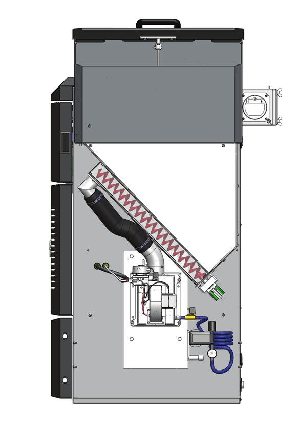
▀ Symbols in the document
           Note!
           The icon is shown when a important notice of the products needs to be understood.

           High voltage
           When the icon is shown extra caution needs to be taken since live parts of the boiler is pos-
           sible to contact without them being isolated. Personal injury or even death may occur! All
           installations must be done by a trained professional and comply with current building redula-
           tions.

           Hot surfaces
           The icon is shown when there is risk for personal scaldings or burns.

    ▀ Introdction

           This guide will not replace the service and/or user manual of the product. The guide is only
           designed to be a help on first start up of the product as well as a guide through the commis-
           sioning process.

           All parts and menus of this document is described in depth in the product manual.

2           Effecta AB - Västra Rågdalsvägen 21 - 434 99 Kungsbacka - 0300 - 22320 - info@effecta.se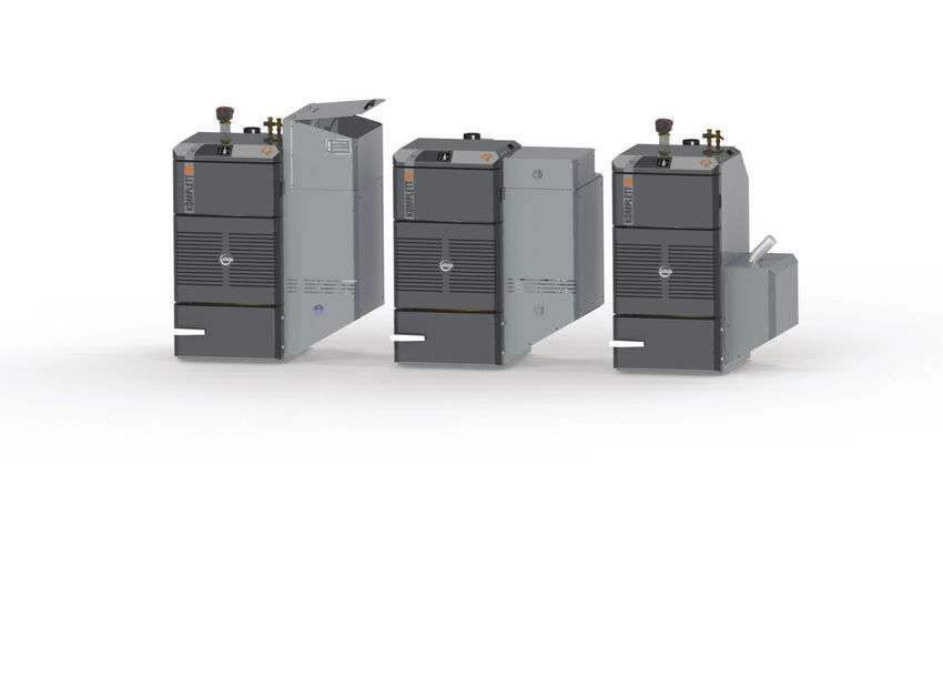
▀ Table of content
P. 2       Introduction
P. 2       Symbol description
P. 3       Table of content
P. 4       Check list before powering up the unit
P. 5       Controller
P. 6       Controller setup - fan
P. 7       Controller setup - feeder
P. 8       Calibration of feed rate - Auger model
P. 9       Calibration of feed rate - Auger model
P. 10      Calibration of feed rate - Integrated fuel store model
P. 11      Calibration of feed rate - Integrated fuel store model
P. 12      Calibration of feed rate - Vacuum fed model
P. 13      Calibration of feed rate - Vacuum fed model
P. 14      Calibration of feed rate - Vacuum fed model
P. 15      Calibration of feed rate - Vacuum fed model
P. 16      Controller setup - effect output
P. 17      Controller setup - date / time
P. 17      Controller setup - function test
P. 18      Back end protection
P. 19      Heating circuits
P. 20      Heating circuits
P. 21      Heating circuits
P. 22      Documentation

        Effecta AB - Västra Rågdalsvägen 21 - 434 99 Kungsbacka - 0300 - 22320 - info@effecta.se   3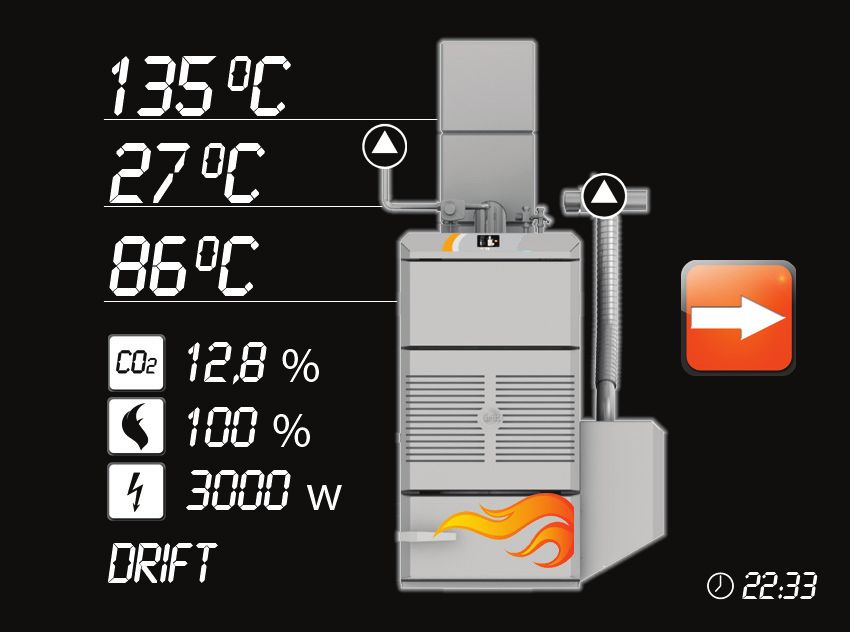
▀ Check list before electrical power feed
    Water content
    Before powering up the system with electrical mains please ensure that all the boiler is filled with
    water. All pumps controlled by the boiler needs to be in water filled heating circuits where there is
    no blockages from circulation.

    Doors
    All doors and cleaning accesses needs to be closed and sealed before powering up.

    Flue / chimney
    The boiler must be connected to a approved flue system to evacuate smoke gasses before powe-
    ring up the boiler.

    Fuel feeding
    Depending on what fuel feed option the boiler is equipped with the fuel feed system needs to be
    completed before power up as well as the storage filled with pellets.

    When above is confirmed please allow electrical mains to the boiler.

4           Effecta AB - Västra Rågdalsvägen 21 - 434 99 Kungsbacka - 0300 - 22320 - info@effecta.se
▀ Control display
Language
Choose desired language by pressing any of the
flags on the screen.

If change of language is desired please open OTH-
ER SETTINGS where language change can be done
again.

Home screen
On the home screen there is a image of the boiler
with temperature readings of the flue, flow of first
heating circuit and boiler temperature.

A CO2 vaule is displayed (only in operation phase) if
the a lambda probe is used.

A flame icon indicates the flame value visual inside
the boiler in percent.

If the electrical heater is used and applicable to the
system a current consumption will be displayed.

At the bottom part a operating mode will normally be
displayed for instance; Ignition, pre operation, opera-
tion phase etc.

Main menu
When pressing the touch display three icons will ap-
pear. In this quick start guide you will be asked to
enter the different menus in order to do different set-
tings.

        Effecta AB - Västra Rågdalsvägen 21 - 434 99 Kungsbacka - 0300 - 22320 - info@effecta.se   5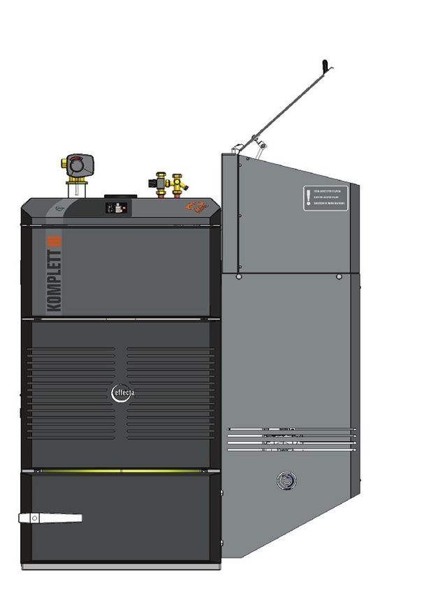
▀ Program setup - fan

    Controller setup
                                                                         Operation settings
    Press anywhere on the display and then press the OPE-                Burner                         Off
    RATION icon.                                                         Fan
                                                                         Feeder settings
    Operation settings menu:                                             Temperature set
    Use the + and - buttons together with OK and the Return              Information
    key to navigate the menu system.                                     Service
                                                                         Installation
    - Confirm that burner is set to OFF.                                 VER: 3.0

    Fan menu:
    Enter the FAN menu, a passcode is required which is                  Fan
    2233. The fan values are set up during operation with                Fan burner                 65%
    a flue analyzer according to the installation manual. We             Flue boiler                75%
    can however recommend the following values to get the                Fan burner low              Off
    boiler operating enough to be able to measure with a flue            Fan alarm                 Tacho
                                                                         Fan alarm                    5s
    analyzer:

                  20kW       25kW        35kW
    Fan burner    55%        65%         55%
    Flue boiler   65%        75%         90%

    The ”Fan burner low” parameter is set to ON if you which
    to have the low power output mode activated. We recom-
    mend to have it activated on a Komplett III Light which di-
    rect feeds any heating circuit without a accumulator tank.

    Please leave the menu by pressing the Return key repea-
    tedly until the home screen appears.

6            Effecta AB - Västra Rågdalsvägen 21 - 434 99 Kungsbacka - 0300 - 22320 - info@effecta.se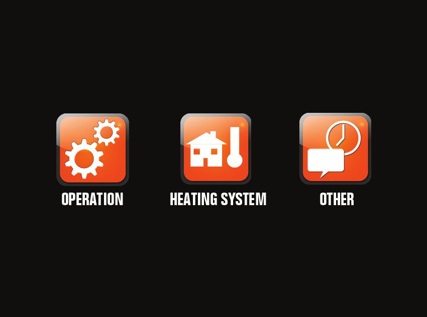
▀ Program setup - feeder settings

Calibration of feed dose
The most critical part of the commissioning is to calibrate the feed doses of pellets correctly. It is
therefore of outmost importance that it is done precisely and according to this manual. If the feed
doses isn´t setup according to our recommendations the boiler will deliver a faulty output which
can damage the system and it will most likely also result in unstable operation of the product.

 Auger fed model                    Integrated fuel store model             Suction model
 The calibration pro-               The calibration process                 The calibration pro-
 cess is described on               is described on page                    cess is described on
 page 8-9.                          10-11.                                  page 12-15.

       Effecta AB - Västra Rågdalsvägen 21 - 434 99 Kungsbacka - 0300 - 22320 - info@effecta.se          7
▀ Calibration of feed dose - Auger version

    Controller setup
                                                                        Operation settings
    Press anywhere on the display and then press the OPE-               Burner                          Off
    RATION icon.                                                        Fan
                                                                        Feeder settings
    Operation settings menu:                                            Temperature set
    Use the + and - buttons together with OK and the Return             Information
    key to navigate the menu system.                                    Service
                                                                        Installation
    - Confirm that burner is set to OFF.                                 VER: 3.0

    Feeder menu:
    Enter the FEEDER SETTINGS menu.                                      Feeder settings
                                                                         Start dose                     50s
    Change the pellets diameter to 6 or 8 mm. pellets.                   Support dose                   10s
                                                                         Pellets diameter                 6
                                                                         Run start dose                  No
                                                                         Run supp. dose                  No
                                                                         Run oper. dose                  No

    Calibration of feed dose with a auger fed boiler:
    If the boiler is attached to a external feeding auger the start dose value needs to be veriefied ac-
    cording to the below information.

    Remove the black plastic hose which connects the feeding auger with the burner unit. Place
    some sort of container underneath the plastic hose to collect the pellets that will be fed during a
    auger filling procedure.

    The hole down the fall shaft to the burner (where the black plastic hose where connected origi-
    nally) needs to plugged temporarily in order to be able to build under pressure in the fire box and
    allow the auger to feed in test mode.

    Enter the OPERATION menu and then INSTALLATION menu. Activate the FILL FEEDER function
    which will force feed pellets for 15 minutes. Meanwhile the auger is filling up tap the auger repea-
    tedly to ensure that it is packed with fuel. When pellets comes out at the end of the auger the fill
    feeder should be set back to NO and then directly back to ON to have a full 15 minutes feed of
    pellets to make sure enough pellets is in the auger. Collect the pellets in a bag or container during
    this 15 minute feed. Do not stop the feeding process, it is critical to have a properly packed and
    filled auger in order to calibrate the feed rate in the next step.

             A correctly adjusted start dose is one of the most critical and important steps of a
             comissioning process. If the start dose is incorrect it will give the wrong output on the
             boiler which might create operational issues, excessive wear on parts and even be
             dangerous in extreme situations.

8            Effecta AB - Västra Rågdalsvägen 21 - 434 99 Kungsbacka - 0300 - 22320 - info@effecta.se
▀ Calibration of feed dose - Auger version
Setting the start dose
                                                                     Operation settings
When the auger is properly packed and full enter the                 Burner                        Off
OPERATION menu and open the FEEDER SETTINGS                          Fan
menu and then press RUN START DOSE.                                  Feeder settings
                                                                     Temperature set
Collect the pellets being fed during the test start dose             Information
                                                                     Service
process. It should be exactly 40cl. If it is less increase the
                                                                     Installation
amount of seconds of the start dose and run another test
It the start dose is greater than 40cl decrease the amount           VER: 3.0

of seconds for the start dose and then run the test start
dose again.
                                                                     Feeder settings
                                                                     Start dose                    50s
Keep testing until the start dose being fed is exactly 40cl.         Support dose                  10s
                                                                     Pellets diameter                6
When this step has been processed the boiler is to be                Run start dose                 No
reassembled again by putting the fall shaft hose back in             Run supp. dose                 No
to the burner.                                                       Run oper. dose                 No

         If the feeder isn´t running it is likely that under pressure over the boiler isn´t sufficient.
         Make sure that the burner fall shaft is plugged at all time when the black plastic fall
         hose is out of the burner.

        Effecta AB - Västra Rågdalsvägen 21 - 434 99 Kungsbacka - 0300 - 22320 - info@effecta.se          9
▀ Calibration of feed dose - Integrated fuel store version
Controller setup
Operation settings
Press anywhere on the display and then press the OPE- Burner Off
RATION icon. Fan
Feeder settings
Operation settings menu: Temperature set
Use the + and - buttons together with OK and the Return Information
key to navigate the menu system. Service
Installation
- Confirm that burner is set to OFF. VER: 3.0
Feeder menu:
Enter the FEEDER SETTINGS menu. Feeder settings
Start dose 50s
Change the pellets diameter to 6 or 8 mm. pellets. Support dose 10s
Pellets diameter 6
Run start dose No
Run supp. dose No
Run oper. dose No
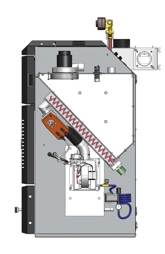
Calibration of feed dose with a boiler equipped with a integral fuel store:
If the boiler is equipped with a intergrated fuel store on any side the start dose value needs to be
veriefied according to the below information.
Remove the front and/or side casing of the fuel store. The internal fuel store and burner unit will
be visual. Remove the black plastic hose which connects the feeding auger with the burner unit.
Place some sort of container underneath the plastic hose to collect the pellets that will be fed
during a auger filling procedure. (See illustration on page 11. for further information)
The hole down the fall shaft to the burner (where the black plastic hose where connected origi-
nally) needs to plugged temporarily in order to be able to build under pressure in the fire box and
allow the auger to feed in test mode.
Enter the OPERATION menu and then INSTALLATION menu. Activate the FILL FEEDER function
which will force feed pellets for 15 minutes. Meanwhile the auger is filling up tap the auger repea-
tedly to ensure that it is packed with fuel. When pellets comes out at the end of the auger the fill
feeder should be set back to NO and then directly back to ON to have a full 15 minutes feed of
pellets to make sure enough pellets is in the auger. Collect the pellets in a bag or container during
this 15 minute feed. Do not stop the feeding process, it is critical to have a properly packed and
filled auger in order to calibrate the feed rate in the next step.
A correctly adjusted start dose is one of the most critical and important steps of a
comissioning process. If the start dose is incorrect it will give the wrong output on the
boiler which might create operational issues, excessive wear on parts and even be
dangerous in extreme situations.
10 Effecta AB - Västra Rågdalsvägen 21 - 434 99 Kungsbacka - 0300 - 22320 - info@effecta.se▀ Calibration of feed dose - Integrated fuel store version
Setting the start dose
Operation settings
When the auger is properly packed and full enter the Burner Off
OPERATION menu and open the FEEDER SETTINGS Fan
menu and then press RUN START DOSE. Feeder settings
Temperature set
Collect the pellets being fed during the test start dose Information
Service
process. It should be exactly 40cl. If it is less increase the
Installation
amount of seconds of the start dose and run another test
It the start dose is greater than 40cl decrease the amount VER: 3.0
of seconds for the start dose and then run the test start
dose again.
Feeder settings
Start dose 50s
Keep testing until the start dose being fed is exactly 40cl. Support dose 10s
Pellets diameter 6
When this step has been processed the boiler is to be Run start dose No
reassembled again by putting the fall shaft hose back in Run supp. dose No
to the burner. Run oper. dose No
The plastic hose is the fall shaft for pellets
in to the burner and should be removed in
order to collect and measure the amount
of pellets being fed.
If the feeder isn´t running it is likely that under pressure over the boiler isn´t sufficient.
Make sure that the burner fall shaft is plugged at all time when the black plastic fall
hose is out of the burner.
Effecta AB - Västra Rågdalsvägen 21 - 434 99 Kungsbacka - 0300 - 22320 - info@effecta.se 11▀ Calibration of feed dose - Suction version
Controller setup
Operation settings
Press anywhere on the display and then press the OPE- Burner Off
RATION icon. Fan
Feeder settings
Operation settings menu: Temperature set
Use the + and - buttons together with OK and the Return Information
key to navigate the menu system. Service
Installation
- Confirm that burner is set to OFF. VER: 3.0
Feeder menu:
Enter the FEEDER SETTINGS menu. Feeder settings
Start dose 50s
Change the pellets diameter to 6 or 8 mm. pellets. Support dose 10s
Pellets diameter 6
Run start dose No
Change the start dose value to 48s which will get you Run supp. dose No
reasonably close to the correct start dose value. Run oper. dose No
A correctly adjusted start dose is one of the most critical and important steps of a
comissioning process. If the start dose is incorrect it will give the wrong output on the
boiler which might create operational issues, excessive wear on parts and even be
dangerous in extreme situations.
12 Effecta AB - Västra Rågdalsvägen 21 - 434 99 Kungsbacka - 0300 - 22320 - info@effecta.se▀ Calibration of feed dose - Suction version
Filling the internal storage
Operation settings
Press anywhere on the display and then press the OPE- Burner Off
RATION icon. Fan
Feeder settings
Operation settings menu: Temperature set
Use the + and - buttons together with OK and the Return Information
key to navigate the menu system. Service
Installation
- Confirm that burner is set to OFF.
Installation menu:
Enter the INSTALLATION menu. Installation
Advanced >
Scroll down to SUCTION SYSTEM and press OK. Fill feeder NO
Effect High speed 15kW
Suction system menu: Effect low sepped 0kW
Testblow start 0s
In the suction system menu scroll down to FILL STORA- Phase out 10s
GE and set the function to ON. Fan Pre oper. 40%
Fan low pre oper. 50%
The filling process will now begin. Clean Phase out 12s
Flame Sens >
NOTE: There is a delay time until the vacuum motor co- Quick Start >
Lam,bda probe >
mes. It will take 2-3 minutes until the turbine comes on Suction System >
and with a empty storage it can take up to 15 minutes Cascade >
until it is fully filled.
Suction system
Filling interval 0 (4)h
Night blockage On
Clean int. storage 1 (25)h
Fill Storage Off
If the feeder isn´t running it is likely that under pressure over the boiler isn´t sufficient.
Make sure that the burner fall shaft is plugged at all time when the black plastic fall
hose is out of the burner.
Effecta AB - Västra Rågdalsvägen 21 - 434 99 Kungsbacka - 0300 - 22320 - info@effecta.se 13▀ Calibration of feed dose - Suction version
Calibration of feed dose on a boiler equipped with a suction unit:
When the on board pellets storage has been filled it is time to calibrate the feed rate.
Remove the front casing of the fuel store. The internal fuel store and burner unit will be visual.
Remove the fall shaft connection by removing the elbow coming out from the storage. For refe-
rence see illustration on page 15.
Place a container underneath the hole to the feeding opening where the elbow used to connect
to the storage to collect the pellets that will be fed during a auger filling procedure.
The hole down the fall shaft to the burner (where the black plastic hose where connected origi-
nally) needs to plugged temporarily in order to be able to build under pressure in the fire box and
allow the auger to feed in test mode.
Enter the OPERATION menu and then INSTALLATION menu. Activate the FILL FEEDER function
which will force feed pellets for 15 minutes. Meanwhile the auger is filling up tap the auger repea-
tedly to ensure that it is packed with fuel. When pellets comes out at the end of the auger the fill
feeder should be set back to NO and then directly back to ON to have a full 15 minutes feed of
pellets to make sure enough pellets is in the auger. Collect the pellets in a bag or container during
this 15 minute feed. Do not stop the feeding process, it is critical to have a properly packed and
filled auger in order to calibrate the feed rate in the next step.
A correctly adjusted start dose is one of the most critical and important steps of a
comissioning process. If the start dose is incorrect it will give the wrong output on the
boiler which might create operational issues, excessive wear on parts and even be
dangerous in extreme situations.
14 Effecta AB - Västra Rågdalsvägen 21 - 434 99 Kungsbacka - 0300 - 22320 - info@effecta.se▀ Calibration of feed dose - Suction version
Setting the start dose
Operation settings
When the auger is properly packed and filled enter the Burner Off
OPERATION menu and open the FEEDER SETTINGS Fan
menu and then press RUN START DOSE. Feeder settings
Temperature set
Collect the pellets being fed during the test start dose Information
Service
process. It should be exactly 40cl. If it is less increase the
Installation
amount of seconds of the start dose and run another test
It the start dose is greater than 40cl decrease the amount VER: 3.0
of seconds for the start dose and then run the test start
dose again.
Feeder settings
Start dose 48s
Keep testing until the start dose being fed is exactly 40cl. Support dose 10s
Pellets diameter 6
When this step has been processed the boiler is to be Run start dose No
reassembled again by putting the fall shaft hose back in Run supp. dose No
to the burner. Run oper. dose No
NOTE: A good value to begin with is 48s for the start
dose. It will take the initial tests close to 40cl. of feed
rate.
The elbow connecting the fall shaft with
the on board storage. Remove it by un-
winding the two M8 nuts.
If the feeder isn´t running it is likely that under pressure over the boiler isn´t sufficient.
Make sure that the burner fall shaft is plugged at all time when the black plastic fall
hose is out of the burner.
Effecta AB - Västra Rågdalsvägen 21 - 434 99 Kungsbacka - 0300 - 22320 - info@effecta.se 15▀ Program setup - temperature set
Temperature set
Operation settings
Press OPERATION and then open TEMPERATURE SET Burner Off
menu. Fan
Feeder settings
In the temperature set menu you will set the desired stop Temperature set
and start temperature of the burners on/off to heat the Information
water volume within the boiler. Our recommendation is to Service
Installation
have on at 65°C and off at 75°C.
These temperatures is not at all the same or in commu-
nication with the heating circuits used to heat the house. Temperature set
It is only the internal temperature within the boiler body. Boiler temp G1 50°C
Stop temp. 80°C
Start temp. 70°C
▀ Program setup - effect output
Effect output
Operation settings
Press OPERATION and then open the INSTALLATION Burner Off
menu. Fan
Feeder settings
Scroll down to Effect high speed and set the boilers high Temperature set
speed output at the desired effect. Never use a higher Information
output than the rating of the product! Service
Installation
If the boiler also will be used with a low power output the
Effect low speed needs to be set. We recommend it to be Installation
Advanced >
50% of the boilers maximum rated output.
Fill feeder No
Effect high speed 20kW
Effect low speed 0kW
Testblow start 0s
Phase out 10s
Fan pre oper. 40%
Fan low pre oper. 50%
Never use a higher output than the maximum rated output of the product!
16 Effecta AB - Västra Rågdalsvägen 21 - 434 99 Kungsbacka - 0300 - 22320 - info@effecta.se▀ Program setup - date & time
Date & time Other settings
Press OTHER and then open the WEEKDAY menu. Weekday >
Time >
Set the correct date and then press return to get back to Calibr. sensors >
the Other setting menu. Function test >
Alarms >
Press TIME to open the menu for the clock. Set the cor- English >
Start guide >
rect local time.
▀ Program setup - function test
Function test of shunt motors Other settings
Press OTHER and then open the FUNCTION TEST menu. Weekday >
Time >
Depending on what functions the boiler have been deli- Calibr. sensors >
vered with a different view will appear in the function test Function test >
Alarms >
menu.
English >
Start guide >
Test the following functions:
Shunt motor 1 (also 2 and 3 if applicable) needs to con-
trolled so that they open in the right direction. Press +/- Function test
and check that they very slowly open in the right direction. Flame sens 0%
Note that it can be either clockwise or counterclockwise Igniter Off
depending on how the shunt valve has been set up. If the Feeder Off
motor is operating in the wrong direction the power freed Fan 100%
phases needs to be switched. Compressor Off
Solenoid valve Off
Test air clean Off
Convection clean Off
Shunt motor 1 (+/-) Off
Radiator pump 1 Off
Shunt motor 2 (+/-) Off
Radiator pump 2 Off
Effecta AB - Västra Rågdalsvägen 21 - 434 99 Kungsbacka - 0300 - 22320 - info@effecta.se 17▀ Back end protection
Back end protection
If one or more heating circuits is connected to the
connections at the back of the boiler the back end
protection function must be enabled at all times.
NOTE: Warranty is void unless the back end protection
function is enabled.
▀ Program setup - back end protection
Back end protection Shunt control 1
Press anywhere on the controller and then open the HEA- Program Constant flow
TING SYSTEM menu. Flow temp. 22 (20)°C
Radiator pump On
Depending on what sensors has been connected to the Constant flow 60°C
Enegy saver >
boiler and what program options the system has been Backend prot. Yes
set up with the HEATING SYSTEM menu will appear dif-
ferently. The one illustrated is displayed if one sensor G7
is attached and the programmer is set to a constant flow
temperature.
Backend prot.
In the shunt control menu scroll down to BACKEND PROT Backend prot. Yes
and press OK. In the BACKEND PROT menu make sure Temp G1 min 60 °C
that the function is set to YES. Max flow temp. 20 °C
Recommended settings:
Temp G1 min: 60°C
Max flow temp: 20°C
Description of function:
The first parameter (Temp G1 min) is the temperature
within the boiler where the Backend protection function
will be enabled. In the above example the function will be
activated when the temperature drops below 60°C. The
function will then restrict the flow temperature down to
the Max Flow temp which in the above example is set to
20°C. Since the draw of hot water is limited to a minimum
while the backen protection function is active the boiler
temperature (G1) will then rise and when the boiler tem-
peratures reaches 61°C the shunt motor will slowly start
to open again.
Boiler warranty is void if the backend protection function isn´t activated when heating
circuits are connected to the back connections of the boiler.
18 Effecta AB - Västra Rågdalsvägen 21 - 434 99 Kungsbacka - 0300 - 22320 - info@effecta.se▀ Heating circuits
Setting up the heating circuits
All Komplett III can control up to three individual heating circuits with a great variety of programs
as well as day/time set back. To set up the heating circuits it is important to have the project docu-
mentation available in order to set the system up as it has been sold originally.
The layout and controls can be done in more than fifty ways and we will in this document try to
explain the basic functions. Please use the users manual as reference if deeper information is
needed.
For the circuits to work you need the following components installed:
Components for heating circuits Amount used per heating circuit
Shunt valve 3 way 1 pcs. per heating circuit
Shunt motor 120s ESBE 1 pcs. per heating circuit
Flow sensor, article 301701 1 pcs. per heating circuit
Outdoor sensor, article 301702 1 pcs. common for all available heating circuits.
Room sensor, article 30171 1 pcs. per heating circuit
▀ Activating the heating system menu
Heating system menus
Shunt control 1
The flow sensors enables and activates the menus for Program Constant flow
each heating circuit. The first flow sensor needs to be Flow temp. 22 (20)°C
connected to G7 on the main board in order to activate Radiator pump On
heating circuit one. The second and third heating circuit Constant flow 60°C
is controlled from the expansion board and are at port G9 Enegy saver >
Backend prot. Yes
and G10.
NOTE: If the flow sensor for the desired heating circuit
isn´t connected the menu for the circuit will not appear in
the controller!
A electrical diagram is available in the full manual for the
Komplett III boilers.
▀ Heating program options
Room
If the program ROOM is choosen the shunt motor will regulate the shunt valve to maintain a certain
room temperature getting it´s reference from the room sensor. One room sensor is used for each
heating circuit using this program. The active sensors in this set up is the flow sensor and room
sensor.
It is possible to use the ENERGY SAVER function to set back the room temperature with the de-
sired amount of degrees on two different times each individual weekday.
Recommended to use when: The building uses radiators and the room sensor is placed in a loca-
tion where it isn´t affected by direct sunlight or chill from doors opening and closing. It should be
placed in a central location of the building and not on a outer wall.
Not recommended to use when: The building uses radiant floor heating / under floor heating.
Effecta AB - Västra Rågdalsvägen 21 - 434 99 Kungsbacka - 0300 - 22320 - info@effecta.se 19▀ Heating program options
Outdoor
If the program OUTDOOR is choosen the shunt motor will regulate the shunt valve to maintain a
certain room temperature getting it´s reference from the outdoor sensor. The temperature to the
flow is determined with the help of a heating curve and adjustment in the program. This is also
known as weather compensation. The same outdoor sensor can be used for all three heating
circuits running on the same program option. The active sensors in this set up is the flow sensor
and the outdoor sensor.
It is possible to use the ENERGY SAVER function to set back the flow temperature with the desi-
red amount of degrees on two different times each individual weekday.
Recommended to use when: The building uses radiators or underfloor heating.
NOTE: The outdoor sensor must be placed on a north facing wall to function properly!
Both
If the program BOTH is choosen the shunt motor will regulate the shunt valve to maintain a certain
room temperature getting it´s reference from the outdoor sensor. The temperature to the flow is
determined with the help of a heating curve and adjustment in the program. This is also known as
weather compensation. The same outdoor sensor can be used for all three heating circuits running
on the same program option.
The difference between to the program BOTH and the program OUTDOOR is that the room
sensor will correct the temperature to the flow with 5°C for every °C the room temperature is off.
Example: If a desired room temp is set at 20°C and the actual room temperature is 19°Cthe tem-
perature to the flow will raise with 5°C until the difference between desired room temperature and
the actual room temperature is 0°C.
The active sensors in this set up is the flow sensor, room sensor and the outdoor sensor.
It is possible to use the ENERGY SAVER function to set back the flow temperature with the desi-
red amount of °C on two different times each individual weekday.
Recommended to use when: The building uses radiators or underfloor heating.
NOTE: The outdoor sensor must be placed on a north facing wall to function properly, the room
sensor needs to be placed at a central location of the house where direct sunlight or chill from
doors doesn´t interfere with the room temperature.
Constant
If the program CONSTANT is choosen the shunt motor will regulate the shunt valve to maintain a
constant temperature to the flow getting it´s reference from the flow sensor.
The active sensors in this set up is the flow sensor.
It is possible to use the ENERGY SAVER function to set back the flow temperature with the desi-
red amount of °C on two different times each individual weekday.
Recommended to use when: Any case where a separate heating controller is used.
20 Effecta AB - Västra Rågdalsvägen 21 - 434 99 Kungsbacka - 0300 - 22320 - info@effecta.se▀ Heating program options
Cylinder
If the program CYLINDER is choosen the shunt motor will regulate the shunt valve to maintain a
constant temperature to the flow getting it´s reference from the flow sensor. This is a very simple
way to control the temperature going to a remote cylinder where there is no possibility to connect
a sensor measuring the actual cylinder temperaure.
The active sensors in this set up is the flow sensor.
It is possible to use the ENERGY SAVER function to set back the flow temperature with the desi-
red amount of °C on two different times each individual weekday.
Recommended to use when: The cylinder is very remote without possibility to connect a sensor.
Cylinder 2
If the program CYLINDER 2 is choosen the shunt motor will regulate the shunt valve to maintain
a set temperature in the cylinder. The cylinder sensor is connected on port G17 on the expansion
board.
The active sensors in this set up is the flow sensor and a sensor in the cylinder.
It is possible to use the ENERGY SAVER function to set back the flow temperature with the desi-
red amount of °C on two different times each individual weekday.
Recommended to use when: Always when a cylinder is used where a sensor can be wired back
to the boiler.
Hydraulic schematics
For hydraulic references please see the full manual for the Komplett III.
Effecta AB - Västra Rågdalsvägen 21 - 434 99 Kungsbacka - 0300 - 22320 - info@effecta.se 21▀ Customer details and information
User name:
User adress:
Installing company:
Effectas order no:
Serial no:
Commissioning engineer:
▀ Customer details and information
Boiler start temp G1 °C
Boiler stop temp G1 °C
Boiler start temp. G6 (only when G5 & G6 is active) °C
Boiler stop temp. G5 (only when G5 & G6 is active) °C
Max G6 (only when G5 & G6 is active) °C
Max G1 (only when G5 & G6 is active) °C
Start dose value S
Start dose measured value cl.
Fan burner %
Flue boiler %
Fan burner low On/Off
Fan burner low (if low effect On) %
Flue boiler (if low effect On) %
Effect high speed kW
Effect low speed (if activated) kW
Back end protection Yes/No
SEND A COPY TO EFFECTA: gunilla@effecta.se
22 Effecta AB - Västra Rågdalsvägen 21 - 434 99 Kungsbacka - 0300 - 22320 - info@effecta.seYou can also read