The FUTURe BelONgs TO IO-lINk - FACTORY AUTOMATION
←
→
Page content transcription
If your browser does not render page correctly, please read the page content below

FACTORY AUTOMATION

The Future Belongs to IO-Link

THE FUTURE BELONGS TO IO-LINK

With its simple approach and cost-saving potential, IO-Link
impresses across the board, from plant design through
installation to operation and maintenance.

    At a glance

    n Long-term cost reductions at all levels
    nS
      tandardized for easy operation
    n Minimized downtimes through intelligent parameter management
    n Comprehensive device diagnosis down to field level
    n Enhanced flexibility in application
    n L ong-term investment security thanks to international standardization

2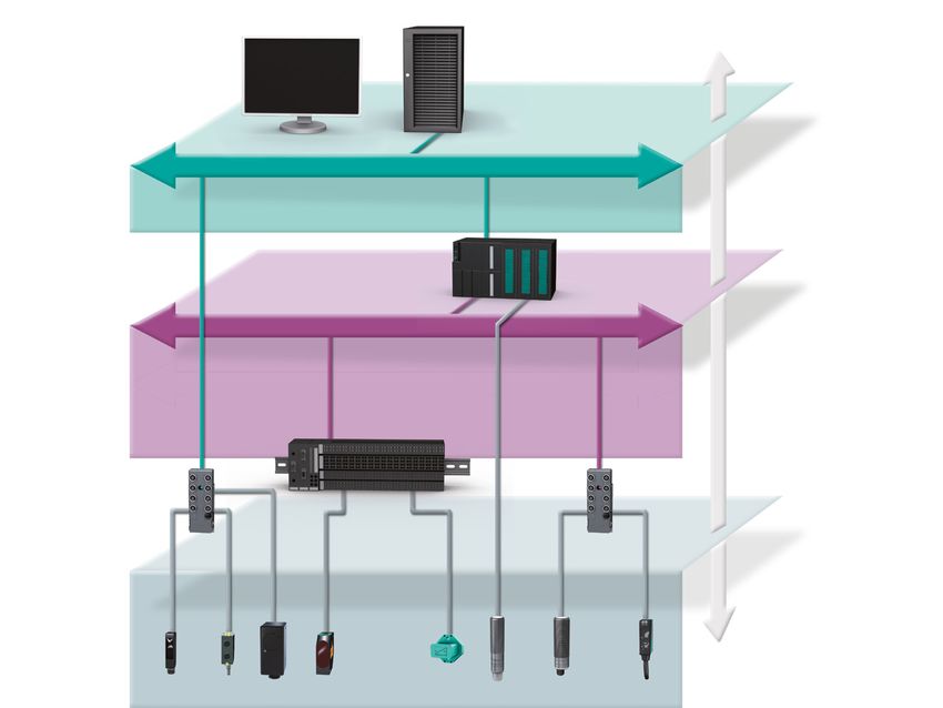
Investment with a future
IO-Link enables continuous communication at the sensor level.
Sensor intelligence is fully integrated, opening up new opportuni-
ties in automation.

IO-Link sensors from Pepperl+Fuchs can be operated on any
master, irrespective of the system. Existing wiring and connection
systems can be used.

Equip your plant for the future so that you can benefit from the
many functions of IO-Link and save costs for many years to come.
International standardization will protect your investment in the
long term.

The standard
IO-Link is an international manufacturer-independent standard
based on IEC 61131-9. Many well-known manufacturers recognize
the standardized communication interface and support IO-Link on
the market. As a leading member of the IO-Link Consortium,
Pepperl+Fuchs has been working on the IO-Link specification with
a view to defining IO-Link as the standard for the future.

                                                                    3
LONG-TERM COST REDUCTIONS AT ALL LEVELS

                                                                                    Planning                            n Economy of Scale
                                                                                                                        n Greater flexibility in planning
                                                                                                                        n Lower volume of spare parts kept in stock

The connection between the sensor and master is established using                                                       ports is reduced. IO-Link can replace analog interfaces completely.
a simple standard 3-wire cable. IO-Link can simultaneously transfer                                                     Parameterization interfaces such as RS232 become superfluous
switching information, measured values, and status information.                                                         because IO-Link transmits process and parameter data simultane-
                                                                                                                        ously. The smaller number of different versions reduces planning
The number of different interfaces, connection cables, and required                                                     costs and the quantity of spare parts kept in stock.

        Reduced interface complexity

n Economy of Scale
n F ewer options reduce ordering and administrative costs
n Lower volume of spare parts kept in stock
                                                                                                                                                                           =                            +

                           Binary sensor with                                                                                                 Binary sensor
                                                                                Analog sensor                                                                            Measuring    Measuring sensors
       Binary sensor        Teach-in function          Analog sensor                                   Complex sensor        Binary sensor      Teach-in,                                                     Complex sensor
                                                                            with parameterization                                                                         sensors    with parameterization
                           and several outputs                                                                                               several outputs

    Switching          Several                   4 mA …                4 mA …        RS232          Ethernet
    output             switching                 20 mA                 20 mA         RS422                                Switching                       Switching infor-                                   Ethernet
                       outputs                   0 V … 10 V            0 V … 10 V                                         output                          mation
                                                                                                                                                          Measured values
                                                                                                                                                          Status information

        Reduced number of control inputs

n Greater flexibility
n Lower planning costs
                                                                                                                                                                           =                            +

4
Installation and                       n Reduced commissioning times
                             Commissioning                        n Convenient operation
                                                                  n Extensive diagnostic options
                                                                  n Localization function
The complicated processes involved in manual device setup are     Standard operating concepts make these tools much easier to
no longer necessary. Individual devices can be cloned easily by   handle.
transferring configuration and parameterization data from one
                                                                  Extensive diagnostic options are available during setup. A mea-
device to another. Commissioning times for series production
                                                                  sured value and the stability or strength of a sensor signal can be
plants are reduced considerably as a result.
                                                                  checked and optimized.
Pepperl+Fuchs provides a vast range of tools for sensor parame-
terization and diagnostics.

     Standardized interface

n Reduced installation and commissioning times
n Save costs on components
                                                                                                   =                  +

     Uniform, standard range of tools

n Simplified configuration, parameterization, and diagnosis
n Short commissioning times
n Flexible on-site or central commissioning
                                                                                                   =                  +

                                                                                                                                        5
LONG-TERM COST REDUCTIONS AT ALL LEVELS

                                            Operation                 n Extensive diagnostic options
                                                                      n Localization function
                                                                      n Requirement-oriented maintenance
                                                                      n Fast recipe changeovers
Extensive diagnostic options during operation provide an indication   Automated parameterization allows the operator to change the reci-
of the operating state as well as other sensor information so that    pes on a large number of devices almost simultaneously. Changing
dirt or wear can be detected before a system failure occurs. This     complicated manual settings locally on individual devices is no lon-
calls for requirement-oriented maintenance. A sensor can be locat-    ger necessary.
ed easily in a plant using the localization function.

    Comprehensive device diagnosis down to field level

n Simultaneous transfer of switching information, measured
  values, and status information
n Evaluation of measured values locally at the sensor or centrally                                   =                  +
   in the PLC
n Access to diagnostic information during normal operation
n Requirement-oriented maintenance prevents system downtime

    Intelligent parameter administration

n Parameter change within seconds
n Recipe change without system downtime
                                                                                                      =                  +

6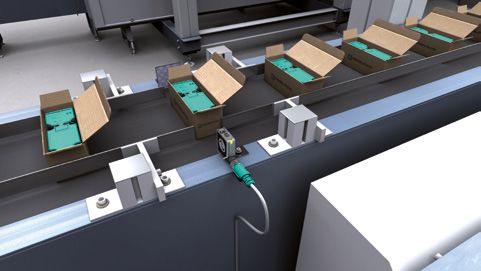
Maintenance                      n Requirement-oriented maintenance
                                                                       n Localization function
                                                                       n Easy device replacement
                                                                       n Minimized downtime
Comprehensive remote diagnosis of the sensor enables commu-            Extensive diagnostic options are available while the plant is operat-
nication down to the lowest field level. The sensors can be local-     ing. These options allow you to customize requirement-oriented
ized accurately.                                                       maintenance cycles, guaranteeing a much higher degree of plant
Automated parameter exchange speeds up the device replace-             availability.
ment process significantly. The complicated manual adjustment
of settings on the sensor is no longer necessary.

     Comprehensive remote diagnosis down to the sensor

n Access to diagnostic information during normal operation

                                                                                                        =                  +
n Preventive maintenance for reduced downtime
n Localization function enables the quick, targeted replacement of
  devices

     Central parameter storage

n Rapid sensor replacement
n Automated reparameterization shortens system downtime
n SIO mode allows backwards compatibility with standard digital
                                                                                                        =                  +
  input/binary sensor

                                                                                                                                          7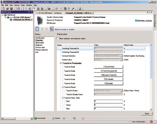
CONSISTENT COMMUNICATION DOWN TO THE SENSOR LEVEL

                                                                           Industrial Ethernet

    FIELDBUS NEUTRALITY

n The IO-Link interface is compatible with existing fieldbuses
n No interference with existing fieldbus topologies                       Fieldbus · sensor/actuator bus
n IO-Link sensors from Pepperl+Fuchs work well with any system

                                                                                                 Bus terminal

                                                                        FIELD
                                                                      MODULE

    MIXED OPERATION POSSIBLE

n In addition to IO-Link sensors, conventional binary sensors can
  be connected to the IO-Link master
n Backwards compatible with standard digital input/binary sensor

8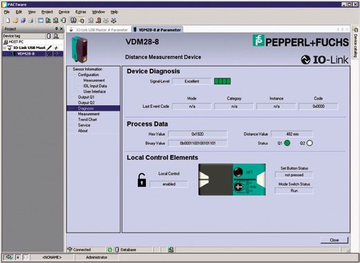
Industrial Ethernet

                                    COMMUNICATION
          PLC

Fieldbus · sensor/actuator bus                          CONSISTENT COMMUNICATION

                                                    n Full use of sensor intelligence and functions
                                                    n Simultaneous transfer of process and ser-
                                                      vice data (parameter and diagnostic data)
                                                    n Measured
                                                              values and data are available to
                                    COMMUNICATION

                                                      higher-level systems without restriction

                     FIELD MODULE                         POINT-TO-POINT CONNECTION

                                                     n Existing connection topologies are
                                                       retained

                                                          STANDARD SENSOR/ACTUATOR CABLES

                                                     n Connection
                                                                  between the sensor and mas-
                                                       ter is established using a simple standard
                                    COMMUNICATION

                                                       3-wire cable
                                                     n No
                                                        special cable or connectors are
                                                       required

                                                                                                    9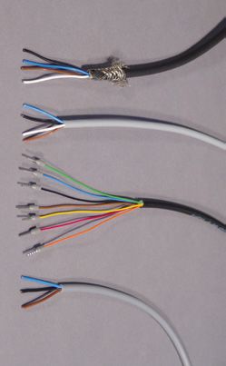
VAST RANGE OF TOOLS FOR STANDARDIZED OPERATION

Pepperl+Fuchs offers you a vast range of tools for
sensor parameterization and diagnostics. Standard
operating concepts offer greater convenience and
simplify overall handling.

     FDT                                                                  IODD Interpreter

 FDT (Field Device Tool) is a standard
	                                                                    Software for integrating IODDs in a FDT operator interface, e.g.,
 for normalizing the interface between                                PACTware™ . The IODD Interpreter “translates” the IODD and pre-
 the device and the operator interface.                               pares the information it contains for the FDT base application by
 Device operation can be integrated                                   adapting the parameters to the same format as DTM device param-
 quickly and easily using the FDT.                                    eters.

     PACTware                                                             DEVICE-SPECIFIC DTM

	PACTware™ is an open, manufacturer-inde-                            In addition to the ever-present IODDs, specific DTMs (Device Type
  pendent user interface compatible with all                          Manager) are available for IO-Link sensors. The device DTMs allow
  fieldbuses according to FDT standards that                          the convenient operation of sensors via a graphical user interface
  enables the operation of devices, systems,                          for visualizing and interpreting configuration, parameter, and diag-
  and communication components throughout                             nostic data.
  the plant.

     IO-Link USB master                                                   IODD

The IO-Link USB master can parameterize any sensor quickly            The IODD (IO Device Description) is a standardized, XML-based
and easily using standardized PACTware™, IODD Interpreter tools,      description of the function and parameters of an IO-Link sensor.
and a PC.                                                             The system tools open a user interface for parameterizing and
                                                                      diagnosing IO-Link devices. The IODD can be used throughout the
                                                                      system. There is one IODD available for each IO-Link device.

     IO-Link Gateway DTM

The IO-Link gateway DTM is required to establish communication to
an IO-Link device via the IO-Link USB master for operation within a
FDT operator interface.

10
PACTware operator
interface
Device-specific DTM using
the example of a DTM for
VDM28 distance sensors
Alternative FDT operator
interface
IODD Interpreter and DTM
using the example of the
IODD of a DK12 print mark
contrast sensor
11IO-LINK PORTFOLIO
IO-Link Portfolio Product name Applications
Distance measurement sensors VDM28-8-L n Positioning
VDM28-50-R n F ill level measurement
VDM28-15-L nD
istance measurement
nC
ollision prevention
Automation light grids LGS8 nO
bject detection and identification
LGS17 nH
eight and tension checks
LGS25 nM
easurement of object size using obstructed beams
LGS50 n S uitable for cold storage warehouse applications
LGS100
Background RL31-8-H n P resence checks
suppression sensor n Tension checks
Photoelectric sensors
n S troke height monitoring
n F ill level monitoring
nC
ollision prevention
Print mark contrast sensor DK12-11 n P rint mark detection
n L abel control
Retroreflective MLV41-6 n P resence checks
sensors and MLV41-55 n Tension checks
background MLV41-54-G n Web break monitoring
suppression MLV41-8-H-120 nM
onitoring stack heights and track loading
sensors MLV41-8-H-500
12Main features Technical data
nM
easurement to object or reflector easuring ranges up to 8 m, 15 m, and 50 m
nM
nS
mall, clearly visible red light spot n L aser light class 1 or 2
nH
igh degree of repeatability irrespective of the surface n R epeat accuracy < 5 mm
nM
inimal black-white difference perating voltage 10 VDC … 30 VDC
nO
n T wo switching points per output n P ulse Ranging Technology
n Immune to ambient lighting
nN
o cross-talk
n Lightning-speed object detection n S ensing range 0.3 m … 8 m
nB
eam crossover with no reduction in response time ptical resolution 4 mm … 100 mm
nO
nS
limline housing design with integrated control evice height 100 mm … 3200 mm
nD
nS
oftware-free adjustment using touch field n B eam gaps 8 mm … 100 mm
n Integrated object detection n 3 -way beam crossover possible
nS
tandby mode provides reduced power consumption and long service life egree of protection IP67
nD
n T emperature range down to -30 °C
n Measuring photoelectric sensor n S ensing range 50 mm … 800 mm
nP
owerBeam transmitter LED n B W/WB difference < 5 %
n L arge, precision-adjustable sensing range perating voltage 10 VDC … 30 VDC
nO
nV
arious operating modes available egree of protection IP67
nD
nC
onsistently small BW/WB difference up to final detection range
n Detects print marks of any color etection range 11 mm
nD
nR
eliable detection, even with low contrast and reflective surfaces n R esponse time 50 µs
nS
uitable for high-speed scanning processes n L ight spot image
n 3 transmitter colors: green, red, and blue n T each-In: dynamic, static, external
n PowerBeam transmitter LED perating voltage 10 VDC ... 30 VDC
nO
n Clearly visible LED function displays LV41-6: detection range 0,1 m – 9,5 m
nM
n Short circuit and undervoltage indicator LV41-55: detection range 0,1 m – 8 m
nM
n Housing resistant to acids and alkalis LV41-54-G: detection range 0 m – 5 m
nM
n MLV41-54-G for reliable detection of transparent objects LV41-8-H-120: detection range 20 mm … 120 mm,
nM
n MLV41-8-H with large, precision-adjustable sensing range BW/WB difference < 3 %
n Various operating modes available LV41-8-H-500: detection range 20 mm … 500 mm,
nM
n Consistently small BW/WB difference up to final detection range BW/WB difference < 5 %
13IO-LINK PORTFOLIO
IO-Link Portfolio Product name Applications
Inductive positioning system PMI14V n Positioning
nD
istance measurement
Positioning systems
n E quipment condition monitoring
30GM ultrasonic sensors UC500-30GM n Positioning
UC2000-30GM n Fill level measurement
UC4000-30GM n Distance measurement
UC6000-30GM n Collision prevention
Ultrasonic sensors
18GM ultrasonic sensors UC1000-18GM n Positioning
n Fill level measurement
n Distance measurement
n Collision prevention
IO-Link USB master IO-Link-Master01-USB n Parameterization of IO-Link devices
n Diagnostic tool for maintenance
Accessories
IO-Link interface IO-Link-Interface-01 n Interface between standard sensors and IO-Link system
n Preprocessing of signals
14Main features Technical data
n Noncontact inductive position measurement n Signal output as IO-Link process data and an analog
n Enhanced position resolution and measured value stability voltage value 0 V … 10 V
n Digital processing of position data n P rogrammable measuring range from 0 mm ... 14 mm
igh position value resolution of ≤ 33 µm
nH
perating voltage 18 VDC … 30 VDC
nO
igh degree of protection IP67
nH
nM
easurement directly to object n Distance is output as IO-Link process data or an analog
nP
rogrammable sound cone width value 0 V … 10 V or 0/4 mA … 20 mA
n High degree of repeatability irrespective of the surface n T wo programmable switching points
n T wo switching points per output perating voltage 10/15 VDC … 30 VDC
nO
n Insensitive to ambient light, object color, and dirt igh degree of protection IP67
nH
n No cross-talk n A mbient temperature range -25 °C … +70 °C
nM
easurement directly to object n Distance is output as IO-Link process data or
n High degree of repeatability irrespective of the surface an analog value
n T wo switching points per output perating voltage 20 VDC … 30 VDC
nO
n Insensitive to ambient light, object color, and dirt igh degree of protection IP67
nH
n No cross-talk n A mbient temperature range -25 °C … +70 °C
n Connection to a PC via USB n IO-Link master with USB2 connection
n Compact, flexible perating voltage 20 VDC … 30 VDC
nO
n Full IO-Link master functionality
n Communication DTM for operating in any FDT environment
n Connection of up to 2 binary or analog sensors n 2 digital or analog inputs
n Speed, rotation direction, or standstill detection n 2 digital outputs, option of selecting PNP or NPN
n Counter and timer function onnection via standard M12 plug
nC
perating voltage 20 VDC … 30 VDC
nO
15Your application. Our challenge. Process interfaces Industrial sensors Intrinsically safe barriers Proximity sensors Signal conditioners Photoelectric sensors Fieldbus infrastructure Industrial vision Remote I/O systems Ultrasonic sensors HART interface solutions Rotary encoders Level measurement Positioning systems Purge and pressurization systems Inclination and acceleration sensors Industrial monitors and HMI solutions AS-Interface Explosion protection equipment Identification systems Wireless solutions Logic control units Solutions for process interfaces www.pepperl-fuchs.com Subject to modifications • Copyright Pepperl+Fuchs • Printed in Germany • Part no. 201648 02/13 04
You can also read