MIRANDA WALL MOUNTED - WALL MOUNTED ELECTRONIC FAUCET FOR COLD OR PREMIXED WATER - INSTALLATION AND MAINTENANCE GUIDE - Kassel

Page created by Frederick Weber
 
CONTINUE READING
MIRANDA WALL MOUNTED - WALL MOUNTED ELECTRONIC FAUCET FOR COLD OR PREMIXED WATER - INSTALLATION AND MAINTENANCE GUIDE - Kassel
WAL L MO U NT E D E L ECT R O N I C FAU CE T
    F O R CO L D O R PR E M I X E D WATE R

  MIRANDA WALL MOUNTED

INSTALLATION AND MAINTENANCE GUIDE
                                                 1
MIRANDA WALL MOUNTED - WALL MOUNTED ELECTRONIC FAUCET FOR COLD OR PREMIXED WATER - INSTALLATION AND MAINTENANCE GUIDE - Kassel
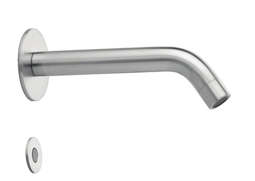
INDEX                                                                                                                                                                      TECHNICAL DATA

1               TECHNICAL DATA

2               PACK CONTENTS

3               PRE-INSTALLATION INFO

4-5             INSTALLATION

6-8             SETTINGS ADJUSTMENT

9               BATTERY REPLACEMENT INSTRUCTIONS

10              MAINTENANCE                                                                                                                                                MIRANDA WALL MOUNTED                 KSL00330         MIRANDA LONG WALL MOUNTED         KSL00340

11              LIMITED WARRANTY

                                                                                                                                                                           Power supply for battery versions:       6 X 1.5 V AA batteries
12              TROUBLESHOOTING
                                                                                                                                                                           Power supply for electricity versions:   9V transformer
                                                                                                                                                                                                                    0.5-8.0 bar (7-116 PSI). With water pressure of more than
                                                                                                                                                                           Recommended water pressure               8 bars, use a pressure reducing valve for reduction
                                                                                                                                                                           Hot water temperature:                   Max. 70º C

                                                                                                                                                                           Sensor type:                             Sense sensor (default)
                                                                                                                                                                                                                    200mm +/- 20mm / 7.87”+/- 0.79” (customizable by
                                                                                                                                                                           Preset sensor range:
                                                                                                                                                                                                                    optional remote control)
                                                                                                                                                                           Security time:                           90 seconds. Can be reduced with optional remote control

                                                                                                                                                                           Sensor type:                             Show sensor (Optional)
The information in this document reflects products at the date of printing. Kassel Sanitar, S.L. reserves the right, subject to all applicable laws, at any time, at its
sole discretion, and without notice, to discontinue or change the features, designs, materials and other specifications of its products, and to either permanently or
temporarily withdraw any of the forgoing from the market. All information in this document is provided “as is” without warranty of any kind, either expressed or                                                    100mm +/- 10mm / 3.94” +/- 0.39” (customizable by
                                                                                                                                                                           Preset sensor range:                     optional remote control)
implied, including but not limited to any implied warranties of merchantability, fitness for a particular purpose, or non-infringement. Kassel Sanitar, S.L. assumes
no responsibility for errors or omissions in the information presented in this document. In no event shall Kassel Sanitar, S .L. be liable for any special, incidental,
indirect or consequential damages of any kind, or any damages whatsoever arising out of or in connection with the use or performance of this information. The
trade names, trademarks, logos and service marks presented in this document, including their design, are the property of Kassel Sanitar, S.L. or other third parties
and you are not permitted to use them without the prior written consent of Kassel Sanitar, S.L. or such third party as may own them.                                       Flow time: (Show sensor)                 8 seconds (customizable by optional remote control

                                                                                                                                                                                                                                                                                1
PACK CONTENTS                                                                                  PRE-INSTALLATION INFO

                                                                                                   Check contents
                                                            1 x Spout and attachments
                                                                                                   Separate all parts from packaging and check each part with the pack contents section.
             1 x Pipe
                                                                                                   Make sure all parts are accounted for before discarding any packaging material. If any
                                                                                                   parts are missing, do not attempt to install the electronic faucet until you obtain the
                                                                                                   missing parts.

                                                                                                   Warnings

                                                                                                   Do not install the system facing a mirror or any other electronic system operated by an
                                                                                                   infrared sensor.

                                                                                                   To prevent reflection problems, it is recommended keep a minimum distance of 1.50
                                                                                                   meters between the faucet and other objects.

                                                                                                   Preparation for installation
                                                        1 x Sense/Show electronic
                                                        unit and attachments                       Flush water supply lines thoroughly before installing the faucet. Do not allow dirt,
                                                                                                   Teflon tape or metal particles to enter the faucet.
    1 x Solenoid and housing with
                                                                                                   All plumbing is to be installed in accordance with applicable codes and regulations.
    filter and filter adaptor
                                                                                                   Care and cleaning of chrome and special finishes

                                                                                                   DO NOT use steel wool or cleansing agents containing alcohol, acid, abrasives, or the
                                                                                                   like. Use of any prohibited cleaning or maintenance products or substances could
    OPERATION WITH OPTIONAL SHOW SENSOR:                                                           damage the surface of the faucet. For surface cleaning use ONLY soap and water, then
                                                                                                   wipe dry with clean cloth or towel. When cleaning bathroom tile, the faucet should be
    Water will be delivered automatically when the                                                 protected from any splattering of harsh cleansers.
    user places a hand within a close distance of
    the sensor eye.
    Water will shut off after the specified run time.
    Default: 8 seconds.
    This solution is ideal for locations were the
                                                              B VERSIONS          E VERSIONS         If system chemical disinfection is practiced, chlorine can be used (calculated
    selected place for the sensor is not necessarily
                                                                                                     chlorine concentration of 50mg/l maximum in water per one hour dwell time) at
    close to the faucet spout.                                Battery box for
                                                                                  9V transformer     service interval frequency
                                                             6 x 1.5V batteries

2                                                                                                                                                                                            3
INSTALLATION                                                                INSTALLATION

                           STEP 1 – INSTALLING THE FAUCET                                            STEP 2 – CONNECTING THE WATER SUPPLY

                                                                                Fit the pipe from the spout base to the solenoid
     1   Shut off the water supply.                                             valve housing
                                                                                Fit the water supply inlet to the filter adapter at
                                                                                the solenoid housing.

                                                       18-25 mm / 0.70”-0.98”
                                                                                Note: Make sure the filter is located between the
                                                                                solenoid housing and the water inlet.

         Drill a hole (18 to 25 mm) in the location
     2
         you wish to install the faucet.
                                                                                                     STEP 3 – CONNECTING THE POWER SOURCE

                                                                                         Connect the cable coming from the
                                                                                  1      sensor unit to the solenoid valve
                                                                                         connector.                                   FROM THE SENSOR   TO THE SOLENOID
         Insert the spout through the wall and
     3   fix the base behind the wall with the
         hexagonal nut and the disk.                                                     Connect the other cable coming
                                                                                         from the sensor unit to the power
                                                                                  2
                                                                                         source connector (battery box or             FROM THE SENSOR   TO THE POWER
                                                                                         transformer).                                                     SOURCE

         Drill a hole (28 to 30 mm) in the
     4   location you wish to install the sensor       28-30mm / 1.10”-1.18”

         unit.                                                                           Turn on the central water supply.
                                                                                  3
                                                                                         Check for leaks.

         Insert the electronic unit through the wall
         or other surface where you want to place                                        If the automatically adjusted sensor range is not satisfactory for your
     5                                                                            4
         it and fix the base behind the wall with                                        purposes, please refer to the section entitled “Settings adjustment”.
         the hexagonal nut and the disk.

4                                                                                                                                                                         5
SETTINGS ADJUSTMENT                                                                            SETTINGS ADJUSTMENT

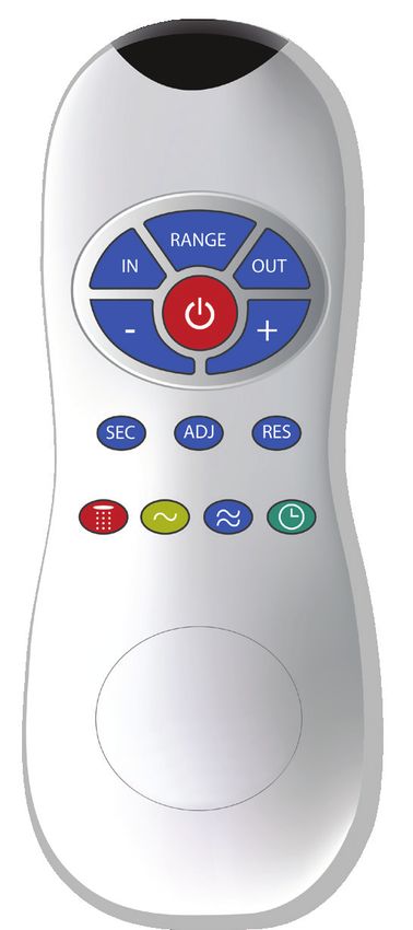
                                                                                                                     DETECTION RANGE: Only if necessary, use the remote control to
        SENSE   DETECTION                                             SENSE   DELAY OUT TIME                         adjust the sensor range as follows:
        SHOW    RANGE
                                                                                                                     Press the RANGE button. Wait until a quick flashing of the LED of
                                                                                                                     the sensor eye is perceived. Then, press + to increase the one level
                                                                      SENSE
                                                                                                     SENSE   SHOW    and – to reduce it every push will increase or decrease one level.
        SENSE   DELAY IN TIME                                                 TEMPORARY
                                                                      SHOW    OFF FUNCTION

        SENSE   SECURITY TIME                                         SENSE                        NOTE: Once you have changed the detection range with the remote control, this
                                                                      SHOW
                                                                              RESET                distance will be remembered by the sensor, even if the power source is disconnected.

        SENSE
                COMFORT FLUSH                                         SENSE
                                                                                                                     SECURITY TIME: The Security time, prevents continuous running
        SHOW                                                                  HYGIENE FLUSH                          of water due to reflections or vandalism. By default, if the sensor
                                                                      SHOW
                                                                                                                     is covered for more than 10 minutes the water flow will shut
                                                                                                                     automatically. To resume regular operation any obstruction must be
        SHOW    FLOW TIME                                                                                            removed.
                                                                                                         SENSE
                                                                                                                     Press the SEC button. Wait until a quick flashing of the LED of the
                                                                                                                     sensor eye is perceived. Then, press + to increase the security time
                                                                                                                     and – to reduce it.

                                                                                                                     DELAY IN TIME: It is recommended to change the delay in time for
                                                                                                                     flush valves for urinals or toilets only.
                                                                                                                     If required, the delay in time can also be modified in showers as
                                                                                                                     follows:
                                                                                                                     Press the IN button. Wait until a quick flashing of the LED of the
                                                                                                         SENSE       sensor eye is perceived. Then, press + to increase the delay in time
                                                                                                                     and – to reduce it.
     Adjusting the settings with the remote control
     If necessary, the sensor settings can be adjusted as following:                                                 DELAY OUT TIME: This button allows modifying the water flow time
     Shut off the water supply. In order to adjust the sensor with the remote control, hold                          after the user removes his hands from the shower. A delay out time
     the remote control straight in front of the sensor in a distance of about 6-8” (15-20cm).                       close to 0 will save more water. An increased delay out time will
     Choose the function you want to adjust by pressing once on one of the function buttons.                         make the user experience more comfortable.
     After pressing once on a specific function button, a quick flashing of the LED at the                           If required, the delay out time can be modified as follows:
     front of the sensor will occur. At this stage, you can change the setting by pressing the                       Press the OUT button. Wait until a quick flashing of the LED of the
                                                                                                         SENSE
     (+) or the (-) buttons, every push will increase or decrease one level. After finishing the                     sensor eye is perceived. Then, press + to increase the delay out
     adjustment, turn the water supply back on.                                                                      time and – to reduce it.

6                                                                                                                                                                                           7
SETTINGS ADJUSTMENT                                                                         BATTERY REPLACEMENT

                                                                                                When the battery weakens, the LED indicator light will blink at a constant rate. The battery
                                                                                                must be replaced within two weeks.
                    24 HOUR HYGIENE FLUSH: This model includes a 24 hours hygiene
                    flush which is disabled. To activate the hygiene flush, press the clock
                    button. Wait until a quick flashing of the LED of the sensor eye is
                    perceived. Then press + to activate the hygiene flush. To disable it
     SENSE   SHOW   again, press – to deactivate it.

                    COMFORT FLUSH: If your model includes a Comfort flush setting, it can                                                                                             ery
                    be activated by pressing the flush button.                                                                                                                Old Batt

                    When the button is pressed, one blink of the LED in the sensor eye is
                    perceived. The pre-programmed flush cycle will take place then.
     SENSE   SHOW   The Comfort flush cannot be interrupted or deactivated by pressing any
                    button until it is over.
                                                                                                1. Unscrew the holding              2 .Carefully open the battery box   3 .Remove the old batteries
                                                                                                screw
                    TEMPORARY OFF FUNCTION: This function is ideal to perform any
                    kind of activity in front of the sensor without operating the system (for
                    example, cleaning).
                    The shower will remain shut for 2 minutes when this button is pressed
     SENSE   SHOW
                    once. To cancel this function and to return to normal operation press
                    the On/Off button again or wait 2 minutes.

                    RESET BUTTON: This function restores all the factory settings except
                    for the sensor range. If required, press the Reset button and without
                    releasing it, press the + button once.
     SENSE   SHOW

                                                                                                4. Replace the used batteries       5. Close the box
                                                                                                with a new 6 X 1.5V batteries
                                                                                                (Lithium battery is recommended).
                    FLOW TIME: This function determines the water flow time once the
                    user operates the system. Press the two waves button. Wait until a
                    quick flashing of the LED of the sensor eye is perceived. Then, press +      IMPORTANT: Spent batteries should not be disposed of with normal household
                    to increase the flow time and – to reduce it.                                waste. Contact your local authority for information on waste disposal and
        SHOW
                                                                                                 recycling.

8                                                                                                                                                                                                     9
MAINTENANCE                                                                                    LIMITED WARRANTY

                                                                                                KASSEL SANITÄR S.L. warrants that its electronic products will be free of defects in material and
 Filter cleaning instructions                                                                   workmanship during normal use for two years from the date the product is purchased.
 This tap is provided with a stainless steel filter preventing foreign particles to enter the
                                                                                                If a defect is found in normal use, KASSEL SANITÄR S.L. will, at its discretion, repair, provide a
 lines. If the water flow has decreased, this may be because the filter is clogged.
                                                                                                replacement part or product, or make appropriate adjustments. Damage caused by accident,
                                                                                                misuse, or abuse is not covered by this warranty. Improper care and cleaning will void the warranty.
 The filter can be cleaned as follows:                                                          Proof of purchase (original sales receipt) must be provided to KASSEL SANITÄR S.L. with all warranty
 1. Shut-off the water shut off valve.                                                          claims.
 2. Disconnect the water supply pipe from the adaptor and disassemble the filter from it.       KASSEL SANITÄR S.L. is not responsible for labor charges, installation, or other incidental
 3. Wash the filter under running water.                                                        or consequential costs other than those noted above. In no event shall the liability of KASSEL
 4. Reassemble the parts.                                                                       SANITÄR S.L. exceed the purchase price of the product.
 5. Restore the incoming water supply.
                                                                                                If you believe that you have a warranty claim, contact your Kassel Distributor, Dealer or Plumbing
 6. Make sure that there is no water leakage.                                                   Contractor. Please be sure to provide all pertinent information regarding your claim, including
                                                                                                a complete description of the problem, the product, model number, the date the product was
                                                                                                purchased, from whom the product was purchased and the installation date. Also include your
                                                                                                original invoice.
 Care and cleaning of chrome and special finishes
 DO NOT use steel wool or cleansing agents containing alcohol, acid, abrasives, or the          KASSEL SANITÄR S.L. AND/OR SELLER DISCLAIM ANY LIABILITY FOR SPECIAL, INCIDENTAL OR
 like. Use of any prohibited cleaning or maintenance products or substances could               CONSEQUENTIAL DAMAGES. This warranty excludes product damage due to installation error,
 damage the surface of the faucet. For surface cleaning of faucet us ONLY soap and water,       incorrect maintenance, wear and tear, battery, product abuse, or product misuse, whether
 then wipe dry with clean cloth or towel. When cleaning bathroom tile, the faucets should       performed by a contractor, service company, or the consumer. This warranty does not cover
 be protected from any splattering of harsh cleansers.                                          product damage caused by the following:
 If system chemical disinfection is practiced, chlorine can be used (calculated chlorine
 concentration of 50mg/l maximum in water per one hour dwell time) at service interval          - Incorrect installation.
 frequency.
                                                                                                - Inversions of supply pipes.

                                                                                                - Pressures or temperatures exceeding recommended limits.

                                                                                                - Improper manipulation, tampering, bad or lapsed maintenance.

                                                                                                - Foreign bodies, dirt or scale introduced by the water supply or sanitizer tank.

                                                                                                - Use of the soap or sanitizer outside of viscosity specifications.

                                                                                                - Alteration of the original soap/foam/sanitizer dispenser components (including pipes).

10                                                                                                                                                                                                     11
TROUBLESHOOTING

  PROBLEM       INDICATOR           CAUSE                                                SOLUTION
 No water       1. Sensor flashes
 coming out     continuously
 of the faucet: when user’s
                                    Low battery.                                        Replace battery
                hands are within
                the sensor’s
                range.
                2. LED in the       1. Range is too short.                              Increase the range
                sensor does not     2. Range is too long.                               Decrease the range
                flash once when
                user’s hands        3. Battery is completely used up                    The battery must be replaced.
                are within the      4. Unit is in “Security Mode”*
                sensor’s range.     5. Sensor is picking up reflections from the
                                                                                        Eliminate cause of reflection.
                                    washbasin or another object.
               3. LED in the        1. Connectors between the electronic unit and      Connect the electronic unit
               sensor flashes       solenoid are disconnected.                         connectors to the solenoid.
               once when                                                               Unscrew solenoid, pull out the
               user’s hands                                                            plunger and the spring from
               are within the                                                          the solenoid and clean them.
               sensor’s range.      2. Debris or scale in solenoid.                    Use scale remover material if
                                                                                       needed. When replacing the
                                                                                       plunger, please make sure that
                                                                                       the spring is in vertical position.
                                    3. The central orifice in the diaphragm is plugged Clean the orifice or replace
                                    or the diaphragm is torn                           diaphragm.
                                                                                       Reduce the supply water
                                    4. The water supply pressure is higher than 8 bar.
                                                                                       pressure.
                                    5. The water supply pressure is under 8 bars and
                                                                                        Shut off water supply and
                                    yet the pressure in the faucet’s body is higher.
                                                                                        unscrew one of the flexible
                                    This situation could be caused by a sudden
                                                                                        pipes in order to reduce the
                                    increase in the water supply pressure that the
                                                                                        pressure that blocks the
                                    back check prevents from dropping, even after
                                                                                        product.
                                    water supply pressure drops under 8 bars.
 Water flow    1. Sensor flashes
 from spout    once when
                                                                                        Clean the orifice or replace
 does not      user’s hands         Debris or scale in diaphragm
                                                                                        diaphragm.
 stop:         are within the
               sensor’s range.
               2. LED in the                                                            Clean or eliminate case of
                                    1. Sensor is dirty or covered.**
               sensor does not                                                          interference.
               flash once when
               user’s hands
               are within the       2. Sensor is picking up reflections from the        Decrease the range or eliminate
               sensor’s range.      washbasin or another object.                        cause of reflection.

 Water flow
                                    Filter or aerator is clogged                        Remove, clean, re-install
 diminished

* “Security Mode”: If the sensor is covered for more than 90 sec. the faucet will automatically shut off water flow.
To return to normal operation remove any blockage.
** In this case, the water flow will stop anyway after 90 seconds because of the security time.

12
KSL01166 05/2020

Kassel Sanitär S.L.
• Avda. de Castilla, 1 - Polígono Industrial, 28830 San Fernando de Henares, Madrid, Spain
• Daimlerstraße 2, D-93133 Burglengenfeld, Germany

Tel. +34 916 778 993 | Fax. +34 916 777 774 | info@kassel.es | www.kassel.es
You can also read