APE: a breadboard to evaluate new phasing technologies for a future European Giant Optical Telescope
←
→
Page content transcription
If your browser does not render page correctly, please read the page content below
APE: a breadboard to evaluate new phasing technologies for
         a future European Giant Optical Telescope
 Frederic Gontea , Natalia Yaitskovaa , Philippe Dierickxa ,Robert Karbana Alain Courtevilleb ,
  Achim Schumacherc , Nicholas Devaneyc , Simone Espositod , Kjetil Dohlene , Marc Ferrarie ,
                                        Luzma Montoyae
        a European    Southern Observatory,Karl-Schwarzschild-Str. 2, Garching, Germany;
                      b Fogale Nanotech,285 rue Gilles Roberval, Nimes, France;
            c Instituto de Astrofisica de Canarias, Address,La Laguna, Tenerife,Espana;
                 d Arcetri Astrophysical Observatory,Largo E. Fermi, Florence, Italy;
          e Laboratoire d’Astrophysique de Marseille,2 Place Leverrier, Marseille, France

                                                 ABSTRACT
The point spread function of a segmented aperture is seriously affected by the misalignment of the segments.
Stringent requirements apply to position sensors and their calibration. The Active Phasing Experiment (APE)
will be a technical instrument aimed at testing possible phasing techniques for a European Giant Optical Tele-
scope (EGOT) in a representative environment. It will also integrate simultaneous control of segmented and
monolithic, active surfaces. A mirror composed of 61 hexagonal segments is conjugated to the primary mirror
of the VLT. Each segment can be moved in piston, tip and tilt and can be controlled in open or closed loop.
Three new types of Phasing Wave Front Sensors dedicated to the measurement of segmentation errors will be
tested, evaluated and compared: a modified Mach-Zehnder sensor developed by the LAM and ESO, a Pyramid
Sensor developed by Arcetri, and a Curvature Sensor developed by IAC. A reference metrology developed by
FOGALE will be added to measure directly the deformation of the segmented mirror and check the efficiency
of the tested wavefront sensors. This metrology will be based on a synthetic wavelength instantaneous phase
stepping method. This experiment will first run in the laboratory with point-like polychromatic sources and a
turbulence generator. In a second step, it will be mounted at a Nasmyth focus of a VLT unit telescope. These
activities are included in a proposal to the European Commission for funding within Framework Program 6.
Keywords: giant telescope, segmented mirror, phasing wavefront sensor, active optics

                                           1. INTRODUCTION
The essential purpose of the APE experiment is to explore, integrate, and validate active, that is low temporal
frequency, wavefront control schemes and technologies for an EGOT. This includes the evaluation and comparison
of the performance of different types of wavefront sensors in the laboratory and on the sky on the one hand and
the integration of the control of a segmented aperture control into an already existing active system (including
field stabilization and active optics) and driving both the active system and the control of the segments from
the output of the full system on the other hand.
To accomplish these taks APE will be designed as a technical prototype which will be installed and tested at a
Nasmyth focus of a VLT unit telescope. The telescope provides all active functions (field stabilization, focusing,
centering, active deformable mirrors) and the APE instrument emulates the optical effects of segmentation. The
latter is done within APE by reimaging the telescope pupil onto a small Active Segmented Mirror (ASM) whose
shape is measured by an internal metrology (IM). The ASM is composed of 61 hexagonal segments and has a
diameter of approximately 15 cm. Each segments is controlled in piston, tip and tilt.
The final wavefront is measured by three new types of Phasing WaveFront Sensors (PWFSs), combined in the
Phasing Metrology Module. The new types of PWFSs are a modified Mach-Zehnder interferometer, a curvature
   Further author information: (Send correspondence to Frederic Gonte.)
E-mail: fgonte@eso.org, Telephone: 0049 89 3200 6852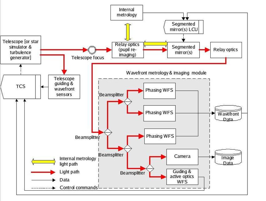
Figure 1. APE Schematic

sensor and a Pyramid sensor. For reference and comparison APE will also be equipped with a Shack-Hartmann
sensor capable of measuring phase errors at segment edges.
APE is a four years project which starts in July 2004.

                                           2. APE PRINCIPLE
Fig. 1 shows the principal components of APE. The light of the star collected by a VLT unit telescope or
generated by a reference source and a turbulence generator is captured by the relay optics which re-images the
primary mirror onto the ASM described in Ch. 3.4. The reflected light is then distributed to the different phasing
sensors (see Ch. 4) and an imaging camera (see Ch. 3.3). An Internal Metrology (IM) described in Ch. 3.5 will
measure the exact positions of the each of the 61 segments. It provides an independent check of the corrections
applied to the segmented mirror. The ASM is controlled by the Telescope Control System (TCS). APE can
work either be used to compare the measurements of the various phasing sensors with the measurements done
by the internal metrology or work as a closed-loop control system correcting the telescope aberrations and the
misalignments of the segmented mirror based on the measurements from one or more of the phasing sensors.
Thereby it also serves as a testbed for the development of a control system for active optics of a telescope with
segmented and flexible mirrors.

                                        3. APE SUB-ELEMENTS
This chapter describes all components of APE except the Phasing sensors which are introduced in chapter 4).
Fig. 2 shows the main components and elements of APE. In the hardware there is a clear distinction between
the new PWFSs and the Shack-Hartman sensor (called Active Optics WFS), which is considered part of the
Guiding & active optics group. It will be a reference against which the other sensors are tested. It will also
supply information on the deformations of the meniscus mirrors in case this can not be delivered by the PWFS.
In the Segmented mirrors group there is one in-pupil mirror, the ASM, and one out of the pupil mirror which
will simulate a secondary segmented mirror on a giant telescope. The latter will either be a static segmented
mirror or a transmissive phase plate.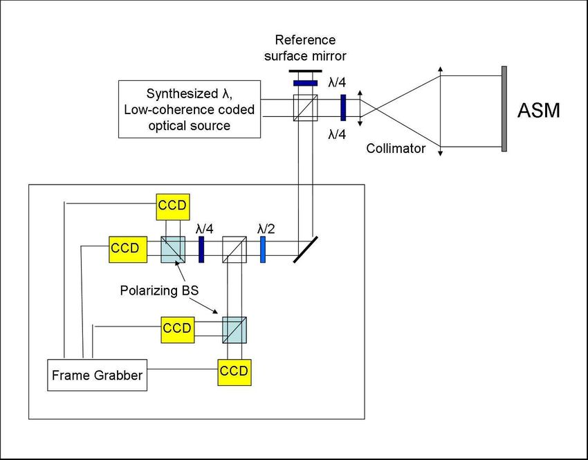
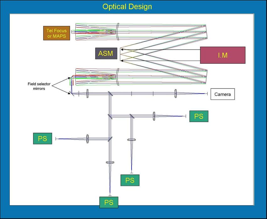
Figure 2. APE hardware Tree

3.1. Optical set up
Fig. 3 shows the optical design. The optical beam at the Nasmyth focus with a focal ratio of F/15, is collimated
by a collimator, reflected by the segmented mirror, and then refocused by another collimator with the same focal
ratio as the first collimator. The beam is then split into 5 different beams for the Phasing WFSs and the imaging
camera. A system of two tip-tilt mirrors directs the light of a star or of the reference source to the WFSs. Each
PWFS receive the same intensity. The static out of pupil mirror or piston plate is not represented in this design.

3.2. Mechanical set up
APE shall be mounted on an optical table with a size of 1.5 by 2.5 m. Since APE will be installed on the
Nasmyth platform of a VLT unit telescope all the all components have to be compliant with the VLT standard.
The derotator will directly be mounted on the interface of the VLT Nasmyth platform. The stability of the star
on the phasing wavefront sensor shall be better than 0.1 arcsec. The calibration system is a copy of the MAD
calibration system (see Marchetti & al.1 ).

3.3. Imaging camera
The imaging camera is composed of an ESO technical CCD having 1024*1024 pixels with a size of 13*13 microns.
The CCD is Peltier cooled to less than -35 degrees Celsius and has a typical readout noise of less than below
50 e/pixel/sec. Its quantum efficiency is better than to 85%. The camera shall have a resolution better than
0.1 arcsec/pixel and a field of view of 1 arcmin. Because of the focal ratio of F/15 at the VLT Nasmyth focus,
which is equivalent to 582 microns/arcsec, we need additional optics to obtain a magnification of 1/2.7.

3.4. Active segmented mirror
The segmented mirror is composed of 61 hexagonal segments as shown in Fig. 4. The size of the segments flat to
flat is between 15 and 23mm. The gap between the segments is 0.15mm. The segments are aluminum coated to
obtain a reflection of more than 85% from 450nm to 1400nm. The misfigure of the segments shall be less than 30
nm wavefront RMS. The segments are controlled in piston, tip and tilt, and the range of the position actuators
shall be between ±5 and ±10 microns. The segmented mirror shall have has a closed loop bandwidth of 5 Hz.
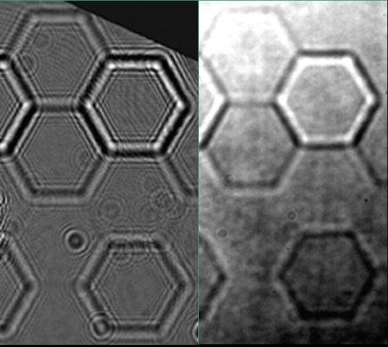
Figure 3. APE Optical Design

   Figure 4. ASM design.
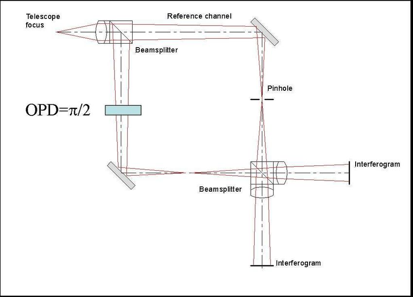
Figure 5. Internal Metrology design.

3.5. Internal metrology
The internal metrology is delivered by FOGALE nanotech. It is a synthetic wavelength interferometer. This
is a polarization Twyman-Green interferometer illuminated by a synthesized wavelength low-coherence coded
optical source. The synthetic wavelength is obtained from 2 wavelengths and can be adjusted by choosing the
right separation between λ1 and λ2 and is given by

                                                        λ1 λ2
                                                  Λ=
                                                       λ1 − λ 2

    The two wavelengths are 850 nm and 800 nm which gives a synthetic wavelength of 13.6 microns. The
resolution of the piston measurement on the segments will be 1 nm RMS. Fig. 5 shows the proposed optical
layout based on a Twyman-Green interferometer which measures the optical path difference between the reference
mirror and the test surface (ASM).

3.6. Turbulence Generator
A combined star simulator and turbulence generator named MAPS has been developed, mounted and tested
at ESO (See Kolb & al.2 ). It can simulate the effects of three turbulent layers in the atmospheres at different
altitudes with a total seeing of up to 0.65 arc second using three transmissive phase screens which are conjugated
to the three altitudes. It also simulates a field of 2 arcminutes containing up to 34 stars. This turbulence
generator will first be used in the experiment MAD (see Marchetti & al.1 ) and then in APE.

                               4. PHASING WAVEFRONT SENSORS
One of the goals of APE is to compare simultaneously the performance of several PWFSs. They will therefore
receive the same amount of light for simultaneous exposures and will use the same VLT technical CCDs with
identical control systems. The four PWFSs to be compared are MAZES proposed by LAM, PYPS proposed by
ARCETRI, DIPSS proposed by IAC/GTC, and a SHAPS which will be supplied by ESO.
Figure 6. MAZES Principle. Figure 7. Measured intensity distribution of arm 1(a), arm 2(b), the interferogram(c) and of the normalized signal(d). 4.1. MAZES: Modified Mach-Zehnder Phasing Sensor MAZES will be designed by LAM and ESO. A schematic view is given in Fig. 6. Its principle has been developed by Natalia Yaitskova, Kjetil Dohlen and Luzma Montoya (see Yaitskova & al. 3 ). The telescope beam is focused inside the Mach-Zehnder interferometer. In one of the two arms at the point spread function at the location of the focus will be filtered spatially by a pin hole with a size of the same order as the size of the image, that is the diffraction pattern in the case without and the seeing pattern in the case with atmosheric disturbances. The segmented mirror is then reimaged after the interference via a lens onto the detectors. The optical phase difference between the two arms must be equal to π/2. This can be achieved by alignment or with a phase plate. The signal is obtained by taking the difference of intensities between the two arms. A prototype has been mounted at the Observatoire de Marseille and tested with a piston mirror. During the test a turbulence generator simulated seeing up to 0.45 arcsecond and r0 = 25.8 cm at 680 nm. The recorded signals are shown in Fig. 7. 4.2. PYPS: Pyramid Phasing Sensor The pyramid sensor has first been proposed by R. Ragazoni (see R. Ragazzoni 4) for use in adaptive optics. PYPS will be developed by ARCETRI. A preliminary theoritical and experimental study has been made by S. Esposito (see Esposito & al.5 ) to adapt it to the phasing of mirror segments. According to this study with a star of visual magnitude 15 the resolution should be better than 40 nm RMS. The principle of PYPS is shown in Fig. 8.
Figure 8. Principle of PYPS.

                                          Figure 9. DIPSS Schematic.

              Figure 10. (a)DIPSS signal no turbulences (b) DIPSS signal with seeing = 0.65 arcsec.

4.3. DIPSS:Diffraction Image Phase Step Sensing
The principle of a curvature sensor has been first described by Roddier. The Institute of Astrophysics of the
Canaries Island (IAC) proposes a modified curvature sensor called DIPPS. The principle has been developed by
Achim Schumacher. (see Schumacher & al.6 ). A schematic view is shown in Fig. 9.

    A preliminary experiment has been done in Garching using a turbulence generator and a piston plate, The
piston plate was composed of 37 segments with 4 levels of piston steps and was placed on the pupil position of
the primary mirror. The experiment has been done with and without turbulence equivalent to a seeing up to 0.6
arcsec. The first analysis of the result shows an error of less than 15 nm RMS without turbulences and better
than 25 nm RMS with seeing of 0.6 arcsec. Further analysis will be done. Fig: 10 shows the signal without and
with atmospheric turbulence.

4.4. SHAPS: Shack-Hartmann Phasing Sensor
The Shack-Hartmann sensor called SHAPS will be developed by ESO. It will be the reference for the other
PWFSs and it will be used also as the guiding and active optics WFS. An ESO technical CCD will be used with
Figure 11. SHAPS.
a size of 1024*1024 pixels. The microlenses will be designed to specifically measure piston, tip and tilt of each
segment. Its principle is shown in Fig. 11.
5. APE CONTROL SYSTEM
The Active Phasing Experiment Control Software (APECS) is required to carry out the APE project. The
control software has to provide the means to interface, control and monitor the various devices needed for this
project. The software will provide all the necessary functionality to evaluate the control system under laboratory
conditions and under the conditions in the VLT environment.
The system must accomplish the coordination between the wavefront analyses done by several PWFSs, control
of the segment mirror ASM and the VLT active optics and the coordination between the imaging camera used
to select the star and the field selector composed of 2 scanning mirrors. It shall control all TCCDs (Technical
CCD) (from the PWFSs and of the imaging camera), the field selector and its scanning mirrors, the ASM, the
3-axis table of the calibration unit, the derotator since APE will be on the Nasmyth platform, the Z-tables for
the imaging camera and the PWFSs (focusing).
APECS shall deliver the control loops of the ASM in open and closed loop with the IM or with any of the PWFS
at up to 5Hz.
The system shall provide extended test facilities, both for individual APE devices and for higher level operation.
The system shall interface the IM with ASM control LCU (Local Control Unit), it also shall interface and control
the VLT TCS-active optics of M1 and M2 with the data from the PWFS and active optics WFS.
The baseline of the control software will be the VLT Common Software (VLTSW).
6. APE MEASUREMENTS CAMPAIGNS
APE Technical runs shall last a year with a first period in laboratory and then a second period on the VLT. The
first period shall last 6 months. the second is on the Paranal mountain and shall consist of 3 campaigns of the
maximum duration of 2 weeks each. Between each campaign we shall reserve 2 to 3 months for the processing
and analysis of the measurements and planning of the next campaign.
REFERENCES
1. E. Marchetti and al, “MAD status report,” in Advancements in Adaptive Optics, Proc. SPIE 5490, 2004.
2. J. Kolb and al, “MAPS: a turbulence simulator for mcao,” in Advancements in Adaptive Optics, Proc. SPIE
5490, 2004.
3. N. Yiatskova and al, “A Mach-Zehnder phasing sensor for extremely large segmented telescopes: Laboratory
results and close loop algorithm,” in Ground-based Telescopes, Proc. SPIE 5489, 2004.
4. R. Ragazzoni, “Pupil plane wavefront sensing with an oscillating prism,” J. Mod. Opt. 43, pp. 289–293, 1996.
5. S. Esposito and al, “Co-phasing of segmented mirrors using pyramid sensor,” in Astronomical Adaptive Optics
Systems and Applications, R. Tyson, ed., Proc. SPIE 4839, pp. 72–78, 2003.
6. A. Schumacher and N. Devaney, “DIPSS: cophasing segmented mirrors with minimal hardware requirements,”
Applied Optics. To be published, 2004.You can also read