STATUS OF THE RAON HEAVY ION ACCELERATOR PROJECT - DONG-O JEON AND HYUNG JIN KIM REPRESENTING THE RAON INSTITUTE FOR BASIC SCIENCE - JACOW (INDICO)
←
→
Page content transcription
If your browser does not render page correctly, please read the page content below
Status of
the RAON Heavy Ion Accelerator Project

        Dong-O Jeon and Hyung Jin Kim
            representing the RAON
          Institute for Basic Science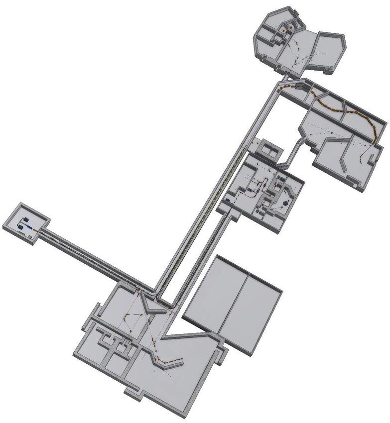
RAON Site

                                                                 1,049,505m2

Supply/Test/Office Bldg

                                                    Exp. Halls

                                       IF Target

                                                                 Post
                                                  Driver
                     Preserved Forest Area                       Accelerator
                                                  SC Linac
                                       Injector

                                             Main Control         Exp. Halls
                                             Center

                                                                               2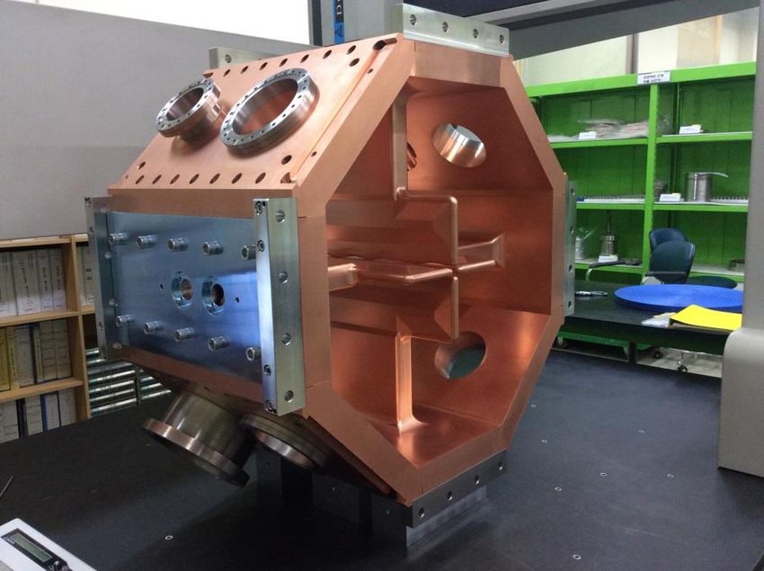
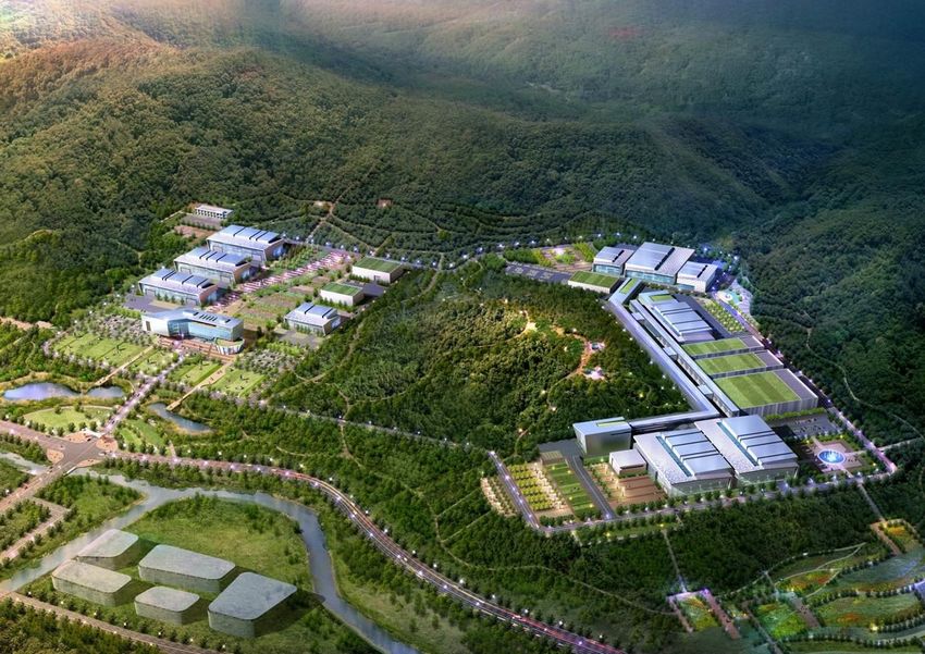
RAON Layout and Beam Parameters
                                                  Driver Linac                   Post Acc.   Cyclotron
                                     High Energy Exp. 2
             Particle                 H+        O +8          Xe+54       U+79   RI beam      proton

             Beam energy (MeV/u)      600       320            251         200     18.5         70
                                      High Energy Exp. 1                                         IF SYSTEM
  Injector
             Beam current (pμA)       660        78             11         8.3       -         1000

             Power on target (kW)   > 400       400            400         400       -          70

                                                                                                ISOL
SCL1(QWR)                                                                                       SYSTEM

                                                                                                  Cyclotron
SCL1(HWR)

                                                              Cryogenic System
                            Low Energy Exp.                                                     Charge Stripper
 SCL2(SSR)

                                                          3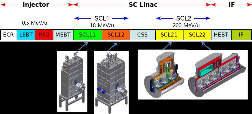
Progress of Accelerator Systems

                             4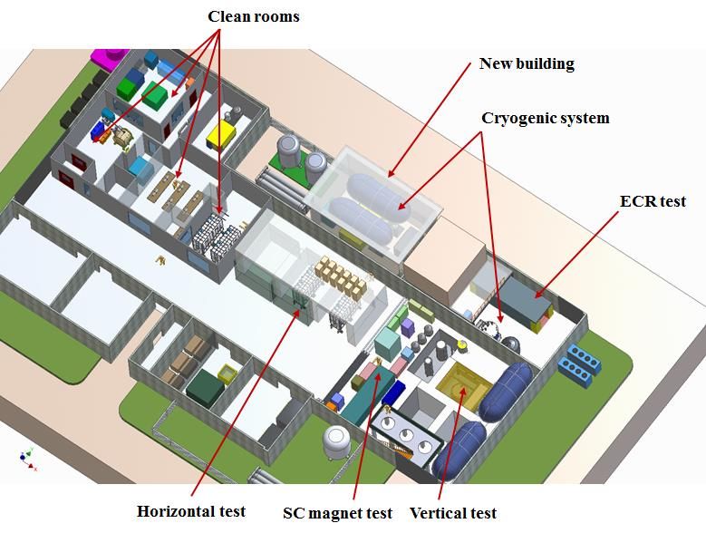
28 GHz ECR Ion Source
• Superconducting sextupole and solenoid
  prototypes were tested and achieved > 30%
  margin.
• Superconducting magnet assembly (sextupole +
  4 solenoids) was completed.
• Cryostat fabrication is in progress and test will be
  performed.
• Preparing for beam test in late 2014.

   Cryostat fabrication      Binj= 3.5 T, Bext= 2.2 T,   Six 4K cryocoolers,
                             Br= 2 Becr , Bmin= 0.7 T    One single stage cryocooler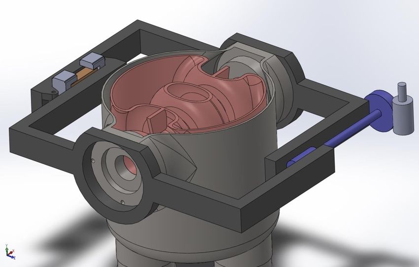
RFQ design parameters

PARAMETER                                  VALUE
Beam Properties:
Frequency                                  81.250 MHz
Particle                                   H+1 to U238+33
Input Energy                               10 keV/u
Input Current                              0.4 mA
Input Emittance: transverse (rms, norm)    0.012 .cm. mrad
Output Energy                              0.507 MeV/u
Output Current for 0.4mA in.               ~0.39 mA
Output Emittance: transverse (rms, norm)   0.0125 .cm. mrad
longitudinal (rms)                         ~26 keV/u-Degree
Transmission                               ~98 %
Structures and RF:
Peak surface Field                         1.70 Kilpatrick
Structure Power (for U238+33)              92.4 kW
Beam Power (for 0.2mA each U238+33&+34)    1.44 kW
Total Power                                94 kW
Duty Factor                                100%
RF Feed                                    1 Drive loops
Mechanical:
Length                                     4.94 meter
Operating Temperature                      TBD Degree C

                                                              6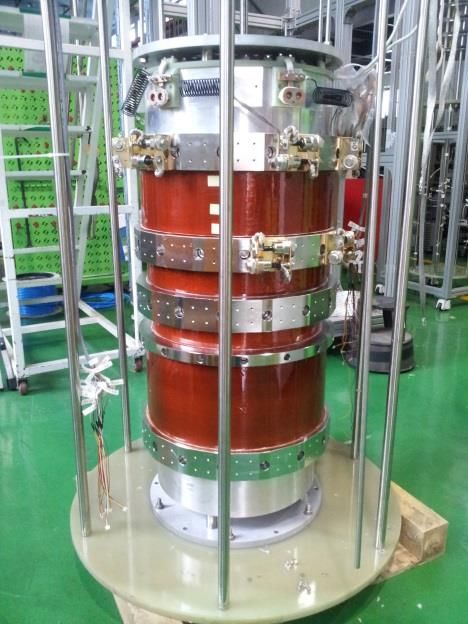
RFQ Engineering Design

LE End                 HE End          Mode separation 1.84 MHz

         Technical design was completed (August 2013)
         and reviewed November 2013.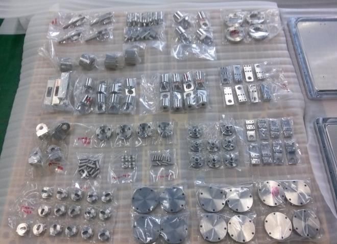
RFQ Prototype
 RFQ Design (2013.08)
 Design review (2013.11)
 RFQ Prototype
- vane machining and 3D measurement
- The 1st brazing failed (2014.04)
- Assessed the related issues
- Brazing procedure modified (2014.05)
- Confirmed brazing procedure (2014.06)
- RFQ prototype to be completed (2014.09)
 RFQ Prototype test
- 15kW SSA, coupler, RCCS are ready

                           RFQ coupler
                           Leak test
                                            Sample brazing test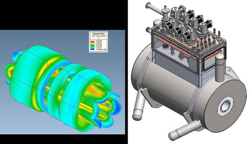
RAON Superconducting Linac
• RAON SCL is designed to accelerate high intensity beams.
• Focusing by NC quad doublets rather than SC solenoids.
• Optimized geometric beta of SC cavities (0.047, 0.12, 0.30,
  0.51).
• Employs larger aperture to reduce beam loss (40 mm and 50
  mm aperture).
• Prototyping of SC cavities and cryomodules is under way at
  present.

                                                      9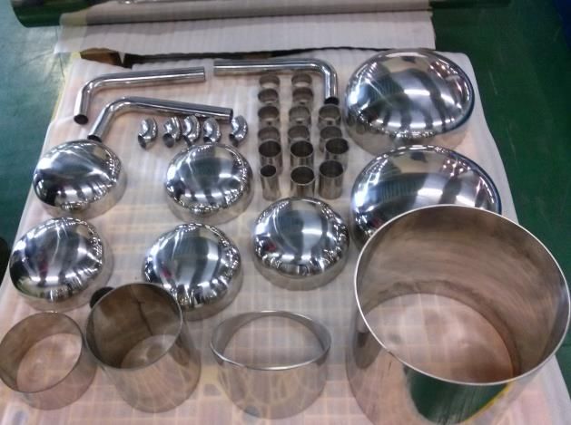
Beam Dynamics
    Lattice Design                           Machine Imperfection Effects
• Transverse emittance increase is less   • Beam centroid exhibits max orbit deviation
  than 20%.                                 of 8 mm.
• Longitudinal emittance is improved.     • It is expected that beam loss will reduce
                                            with orbit correction.
                                                                                   Charge
                                                                                   Stripper
                                                                                   Section

                                            Item         Quantity         Error        Distribution
                                            Cavity       Misalignment     1mm          Uniform
                                                         Tilt             5 mrad       Uniform
                                                         Voltage, phase   1%, 1°       Gaussian
                                            Quadrupole   Misalignment     0.15mm       Uniform
                                                         Tilt             5 mrad       Uniform
                                                         Magnetic field   1%           Gaussian

                                                                                        10
Beam Diagnostics Configuration
Beam box
quadrupole
• 8 ports to install
diagnostics, collimators,
vacuum
11Superconducting cavity
QWR HWR
Parameters Unit QWR HWR SSR1 SSR2
bg - 0.047 0.12 0.30 0.51
F MHz 81.25 162.5 325 325
Aperture mm 40 40 50 50
QRs Ohm 21 42 98 112
R/Q Ohm 468 310 246 296
Vacc MV 0.9 1.3 1.9 3.6
Epeak/Eacc 5.6 5.0 4.4 3.9
SSR1 SSR2 Bpeak/Eacc 9.3 8.2 6.3 7.2
Qcalc/109 - 1.7 4.1 9.2 10.5
Temp. K 4.5 2 2 2
12Design of SC Cavity
Optimization of Cavity Parameters Mechanical analysis
Multipacting analysis Frequency shift
Frequency shift QWR
Resonant Frequency 81.25MHz
Cavity length(upper) -67.1kHz/mm
Cavity length(lower) +1.3kHz/mm
Welding (0.58mm shrink) +38.2kHz
EP/BCP (125um) +267kHz
External pressure(Vacuum, L-He) -4.6Hz/mbar
Cool down(293K2K) +203kHz
Lorentz Detuning -1.7Hz/(MV/m)2
13SC Cavity Prototyping
CAVITY Manufacturing Process
MATERIAL INSPECTION DEEP DRAWING MACHINING
3D SCAN (CMM) BCP EBWSC Cavity Prototyping
QWR Final EBW HWR Final EBW
SSR1 Clamp-up Test SSR2 Clamp-up Test
Prototype superconducting cavities are fabricated through domestic vendors.Tuner Prototyping
PZT Hinge Motor
(Optional) Connection
Cavity
Jacket 1:20 Worm &
worm wheel
Rack & pinion
Tuner Design
•Lever (1:2~2.5) & Worm-worm wheel (1:20) mechanism – MAX 1:50
•Vacuum Interface : Rotary Feedthrough
•Actuator : Step Motor & PZTCoupler Prototyping
• Prototyping: SNU (Aug. 2013~Feb. 2014) • Prototyping: IHEP (Mar. 2014~Dec. 2014)
– Performance test in progress • Frequency: 162.5 MHz
• Frequency: 325 MHz
• Nominal Power: 3.7 kW
• Nominal Power: 14.5 kW
T-box
Window
assembly
with inn
er condu
ctor
Outer co
nductor
IBS Coupler
Window and Inner conductor with air co
RF power :4kW oling is available.
Air
Inner conductor
WindowCryomodule Prototyping
QWR Cryomodule HWR#1 Cryomodule HWR#2 Cryomodule Thermal load (4.5K equivalent, W)
Without margin
Module
Static Dynamic Total
QWR 227 532 760
HWR1 389 557 945
HWR2 682 1,459 2,141
SSR1 475 1,014 1,489
SSR2 790 5,009 5,800
Total 2,563 8,572 11,135
SSR#1 Cryomodule SSR#2 Cryomodule
tolerance unit
X ±0.25mm
Y ±0.25mm
Z ±0.5mm
Pitch ±0.1˚
Yaw ±0.1˚
Roll ±0.1˚
18Cryomodule prototyping in progess
HWR#2 Cryomodule
Vac. chamber Ass’y
Vacuum chamberCryomodule prototyping in progess
Cryomodule components fabrication
Thermal shield
Cryomodule components Thermal shield parts
Cryogenic pipe line
Cryogenic pipes Dummy cavity and pipe partsIn-flight Fragment (IF) System
• U beam to C target generates various rare isotope beams.
• Separator’s function is to separate rare isotope beam of
interest.
• Nonlinear term correction of IF Separator is undertaken.
• Technical design of Beam Dump is proceeding.
• HTS(High Tc Superconductor) quadrupole coil prototyping
is in progress (in collaboration with KERI).
• LTS(Low Tc Superconductor) quadrupole prototyping is in
progress.
21IF System
First order optics of In-flight separator
Characteristics of In-flight separator
Maximum magnetic rigidity: ~10 Tm
Momentum acceptance: ± 3%
Angular acceptance : ±40 mrad (H)
± 50 mrad (V)
Focal plane
Achromatic: F2, F4, F5, F7
Momentum dispersive: F1, F3, F6, F8
Doubly achromatic: F9
Momentum resolving power
pre-separator: 1140 at F1
2280 at F3
Main separator: 2600 at F6
2600 at F8
Transfer matrix coefficient at X- direction
F1 F2 F3 F4 F5 F6 F7 F8
[X,X] -2.08 2.18 -2.39 2.00 -2.37 2.00 -2.38 2.02
[X,D] 2.30 0.00 -2.92 0.00 2.71 0.00 2.77 0.00Second order optics of In-flight separator
High order correction Beam distribution in X–A phase space
nd
Before 2nd order correction Before 2nd order After 2 order
correction correction
F3
F6
After 2nd order correction
Tilt angle (degree)
F3 F6 F8
Before 2nd order
-87.7 88.2 88.8
correction
After 2nd order
0 0.02 0.01
correctionHTS Q-magnet
• In the target region, magnets are Pre
Separator
under the influence of high radiation.
• Magnets are subjected to High
radiation
region
high radiation heat loads, and it should
be resistant to the radiation damage.
Main
Separator
• Benefits of HTS magnets in Fragment Separator
– Technical Benefits
HTS provides large temperature margin – HTS can tolerate a large local and global increase
in temperature caused by beam-induced heating.
– Economic Benefits
Removing large heat load at higher temperature (~50 K) rather than at ~4 K (LTS) is more
efficient.
– Operational Benefits
The temperature need not be controlled precisely. more robust magnet operation.
24HTS Q-magnet
• HTS Q-magnet prototype
An HTS coil for HTS Q-magnet
Design Parameters (HQs_R12)
Aperture radius (mm) 120
Pole tip radius (mm) 130
Effective length (mm) 579
- bobbin, current terminal, cooling channel..
Yoke length (mm) 480
- Winding Field gradient (T/m) 15
Pole tip field (T) 1.95
Full scale HTS coil for HTS Q-magnet Total current (kA) 121
Design modification 864
Coil size (mm2)
(36 mm x 12 mm x 2)
- Manufacture of 4 HTS coils
Current density (A/mm ) 2 140
- Full coil assembly
- Series connected coil Turn number (N) 164
Operating current (A) 370
Critical current 640 A (SuperPower)
One turn length (m) 1.57/1.63
HTS Q-magnet
2.25
Final design Total length of HTS tape (km)
(562 m / 1 coil)
Volume of coil (cm ) 3 4028
- Machining of iron yoke
- Coil-yoke-cooling channel interface
B //c (T) 2.1
(Thermal and Mechanical) Field uniformity (%)
- Full system assembly 0.6%
(for 12th harmonic order)
25HTS Q-magnet
• Test results of HTS coil prototype
Conduction plate
(TL) Vacuum Chamber
HTS Prototyping
Coil
(TU) (TD)
[ HTS coil in liquid nitrogen for experiment ] Cryocooler
- Temperature :
300 K~5 K
(TR) - Current :
[ HTS coil for conduction cooling test Max. 400 A
and the position of temperature sensors]
[ Conducting cooling system ]
300 TR
TL
TU
250
TL
Temperature [K]
200
150
[ Voltage and magnetic field during ramp-up ]
100
- Measured critical current = 202 A (expectation = 207 A ) 50
- No Ic degradation observed after several times of cool-down
and warm-up.
0
0 1 2 3 4 5 6 7 8 9 10 11 12 13 14 15 16 17 18 19
- Metal (stainless steel) insulator has enough resistance Time [hour]
[ Temperature traces at cool down]
to prevent the current flowing across the insulator in normal state.
- Cool down time : about 18 hours (300 K 50 K)
- Critical current tests at conduction cooling
are in progress. 26LTS Q-magnet
Parameters LQ1 (2)
Pole tip radius 180 mm
Nominal length 550 (900) mm
Yoke length 450 (800) mm
Yoke diameter 1000 mm
Field gradient 15 T/m
Total current ~ 300 kA
LTS Q-magnet with multi-pole coil Bmax in the coil ~ 4.1 T LTS Q-magnet triplet cryostat design
Quadrupole coil test result Heat treatment & Ultrasonic examination
27Graphite target for high-intensity beam
Beam Dump

            29
Radiation Heating Calculation
& Remote Handling System
117m
pre-separator main separator
IF separator layout 46m
Driver
Preserved Forest Area IF Target
Remote
SC LinacHandling(RH) System
Injector
Target Hot cell
Primary beam Q1 Q2 Q3 H1
to the Production
Target Collimator Access gate
Main Control Exp. Halls
Center
RH devices
of the Hot cell
Radiation Heating Calculation were performed
for the Hot cell components using PHITS vacuum chamber
*MSM: master-slave manipulatorsSRF Test Facility
SRF TF is constructed at KAIST
Munji campus.
It will be ready for operation in 2015.
SRF TF includes :
2 vertical test stands
3 cryomodule test benches
1 buffered chemical processing
2 high pressure rinsing
1 high temperature furnace
1 ultrasonic clean
Cryogenic system
31Budget and Schedule
• RISP budget
Accelerator and Experimental Systems : $420M (460.2T KRW)
Conventional Facility : $568M (624.3T KRW)
• Conventional facility budget was finalized May 2014.
• Construction to be completed by 2021.
CD : Conceptual Design 2012 2013 2014 2015 2016 2017 2018 2019 2020 2021
TD : Technical Design 1 2 3 4 1 2 3 4 1 2 3 4 1 2 3 4 1 2 3 4 1 2 3 4 1 2 3 4 1 2 3 4 1 2 3 4 1 2 3 4
We are here!
CD
SC Cavity
TD 1st article
Accelerator Prototyping
Accelerator Fabrication
RISP Baseline Technical
Design Design Accelerator Install & Commission
Summary Report
Exp System Prototyping
Exp System Fabrication
Exp System Install & CommissionSummary
• The RAON has phased into prototyping stage.
• Fabrication of ECR Ion Source is in progress and beam test in
late 2014.
• Superconducting magnet assembly is fabricated and being tested.
• RAON is undertaking prototyping efforts:
• RFQ
• Superconducting cavities through domestic vendors and international
vendors
• Cryomodules through domestic vendors
• HTS(High Tc Superconductor) quadrupole coil in collaboration with
domestic research institutes
• LTS(Low Tc Superconductor) quadrupole
• The conventional facility budget for the RAON was finalized May
2014.
33• MOPP080, H. Jang, Beam Dynamics Study for RAON Superconducting
Linac
• MOPP081, M.J. Joung, The ECT System for RAON’s Cavities
• MOPP082, H.J. Kim, Superconducting Linac for RISP
• TUPP085, W.K. Kim, RAON Cryomodule Design for QWR, HWR, SSR1 and
SSR2
• TUPP086, H. Kim, RAON Superconducting Radio Frequency Test Facility
Construction
• TUPP088, M. Lee, QWR/HWR type cryomodule prototype design for the
RAON
• TUPP083, M.O. Hyun, Design and Analysis of Slow Tuner in the
Superconducting Cavity
• TUPP084, J.D. Joo, Surface Treatment Facilities for SCRF cavities at RISP
• THPP079, H,J. Cha, Prototyping Progress of SSR1 Single Spoke Resonator
for RAON
34Thank you for your attention!
감사합니다
35You can also read