PUBLICATION Future Circular Collider
←
→
Page content transcription
If your browser does not render page correctly, please read the page content below
CERN-ACC-2019-0009

                            Future Circular Collider

                            PUBLICATION

 EIR key component functional design
specifications for perliminary Baseline:
            Milestone M3.4

               Tomas Garcia, Rogelio (CERN) et al.

                                 17 January 2019

               The European Circular Energy-Frontier Collider Study
               (EuroCirCol) project has received funding from the Eu-
               ropean Union’s Horizon 2020 research and innovation
               programme under grant No 654305. The information
               herein only reflects the views of its authors and the Eu-
               ropean Commission is not responsible for any use that
               may be made of the information.

The research leading to this document is part of the Future Circular Collider Study

               The electronic version of this FCC Publication is available
                on the CERN Document Server at the following URL :
EIR KEY COMPONENT FUNCTIONAL EuroCirCol-P3-WP3-M3.4
DESIGN SPECIFICATIONS FOR Date: 30/07/2018
PRELIMINARY BASELINE
Grant Agreement No: 654305
EuroCirCol
European Circular Energy-Frontier Collider Study
H o r i zo n 2 0 2 0 R e s e a r c h a n d I n n o v a t i o n F r a m e w o r k P r o g r a m m e , R e s e a r c h a n d I n n o va t i o n A c t i o n
MILESTONE REPORT
EIR
KEY COMPONENT FUNCTIONAL DESIGN
SPECIFICATIONS FOR PRELIMINARY BASELINE
Document identifier: EuroCirCol-P3-WP3-M3.4
Due date: End of Month 38 (August 1, 2018)
Report release date: 30/07/2018
Work package: WP3 (Experimental Interaction Region)
Lead beneficiary: UOXF (JAI)
Document status: RELEASED (V1.0)
Abstract:
Report on the list of key accelerator elements for the collider experimental insertion region and its
functional design properties, based on the existing preliminary EIR design baseline. The report
indicates also the foreseen quantities and constraints on the infrastructure (e.g. experiment cavern and
machine-detector-interface elements) so to permit coming to an overall cost estimate of the collider.
Grant Agreement 654305 PUBLIC 1 / 11EIR KEY COMPONENT FUNCTIONAL EuroCirCol-P3-WP3-M3.4
DESIGN SPECIFICATIONS FOR Date: 30/07/2018
PRELIMINARY BASELINE
Copyright notice:
Copyright © EuroCirCol Consortium, 2015
For more information on EuroCirCol, its partners and contributors please see www.cern.ch/eurocircol.
The European Circular Energy-Frontier Collider Study (EuroCirCol) project has received funding
from the European Union's Horizon 2020 research and innovation programme under grant No
654305. EuroCirCol began in June 2015 and will run for 4 years. The information herein only
reflects the views of its authors and the European Commission is not responsible for any use that
may be made of the information.
Delivery Slip
Name Partner Date
Rogelio Tomas
Authored by CERN 18/07/18
Roman Martin
Julie Hadre
Edited by CERN 18/07/18
Johannes Gutleber
Michael Benedikt
Reviewed by CERN 25/07/18
Daniel Schulte
Approved by EuroCirCol Coordination Committee 30/07/18
Grant Agreement 654305 PUBLIC 2 / 11EIR KEY COMPONENT FUNCTIONAL EuroCirCol-P3-WP3-M3.4
DESIGN SPECIFICATIONS FOR Date: 30/07/2018
PRELIMINARY BASELINE
TABLE OF CONTENTS
1. List of key accelerator elements for the collider EIR ..................................................................... 4
1.1. Magnets ................................................................................................................................... 4
1.2. Beam position monitors .......................................................................................................... 6
1.3. Crab cavities ............................................................................................................................ 6
2. Infrastructure .................................................................................................................................. 7
2.1. Machine-Detector-interface .................................................................................................... 7
2.2. Experimental Caverns and tunnel ........................................................................................... 8
2.3. Power Supplies ........................................................................................................................ 8
3. Conclusions .................................................................................................................................... 9
4. References .................................................................................................................................... 10
5. Annex glossary ............................................................................................................................. 11
Grant Agreement 654305 PUBLIC 3 / 11EIR KEY COMPONENT FUNCTIONAL EuroCirCol-P3-WP3-M3.4
DESIGN SPECIFICATIONS FOR Date: 30/07/2018
PRELIMINARY BASELINE
1. LIST OF KEY ACCELERATOR ELEMENTS FOR THE COLLIDER EIR
1.1. MAGNETS
The final focus triplet is central to the performance of the collider. FCC-hh features two high
luminosity EIRs and two low luminosity EIRs with individual magnet parameters each. Furthermore
the high luminosity EIRs have a baseline design with round beam that require crab cavities to
compensate the luminosity reduction due to crossing angles, and an alternative design compatible with
flat beam in case crab cavities cannot be realised. The relevant magnet parameters for the single
aperture triplet magnets are shown in Table 1 to 3
Table 1: Baseline triplet parameters of the high luminosity EIRs.
Magnet Length [m] Maximum Inner coil Number Shielding
Gradient [T/m] diameter thickness
[mm] [mm]
Q1 14.3 130 164 8 35
Q2 12.5 105 210 16 35
Q3 14.3 105 210 8 35
Table 2: Alternative triplet parameters of the high luminosity EIRs.
Magnet Length [m] Maximum Inner coil Number Shielding
Gradient [T/m] diameter thickness
[mm] [mm]
Q1 15.0 108 193.2 8 44
Q2 15.0 112 193.2 12 33
Q3 15.0 98.5 193.2 8 24
.
Table 3: Triplet parameters of the low luminosity EIRs
Magnet Length [m] Maximum Inner coil Number Shielding
Gradient [T/m] diameter thickness
[mm] [mm]
Q1 10.0 265 64 8 10
Q2 15.0 270 64 8 10
Q3 10.0 260 64 8 10
The cryostats of the triplet quadrupoles will have to be designed so they can support thick and
consequently heavy shielding inside the coil apertures. It should be noted that the required number
given in the tables corresponds to the number of magnets needed for operation, it does not include a
spare policy nor replacements that might become necessary due to radiation damage. However,
simulations of collision debris suggest that the low luminosity triplet can withstand the whole
integrated lifetime luminosity of 5 ab-1, while the high luminosity triplets have to be exchanged not
more than once per 30 ab-1 if at all. The latter will depend on the survivable dose of the coil insulator,
Grant Agreement 654305 PUBLIC 4 / 11EIR KEY COMPONENT FUNCTIONAL EuroCirCol-P3-WP3-M3.4
DESIGN SPECIFICATIONS FOR Date: 30/07/2018
PRELIMINARY BASELINE
as well as the effectiveness of several mitigation strategies currently being worked on. These strategies
include regular changes of the crossing plane and a specifically designed Q1 magnet. The crossing
plane alternation will require a hardware exchange of the crab cavities.
In addition to the triplet, the high luminosity EIRs have four double aperture matching quadrupoles on
each side of the IP. The low luminosity EIRs use adjacent injection section to match the optics, so they
only include 4 matching quadrupoles on one side of the IP and two on the other side.
Table 4: Parameters of the matching section quadrupoles
Magnet family Length [m] Maximum Aperture Number
gradient [T/m] diameter [mm]
MQY 9.1 200 70 8
MQYL 12.8 260 60 8
MQML 12.8 300 50 8
MQM 14.3 400 50 8
Not included in Table 4 are the magnets of the injection section as indicated in Figure 1, or the
dispersion suppressors. The possible maximum gradient of the MQM magnets is currently being
reassessed. It should be possible to replace the 8 MQM type magnets by 12 shorter and slightly weaker
quadrupoles.
Figure 1: Layout of the low luminosity EIR. Only the experimental part (highlighted in green) is considered in this report
Behind the triplet region, the two counterrotating beams are separated by single aperture dipoles D1
and then brought back into parallel orbits with double aperture recombination dipoles, D2. In the case
of the high luminosity EIRs, normal conducting dipoles, similar to the MBXW and MBW designs of
the LHC, were chosen because of the radiative environment and because they can provide better field
quality. In the low luminosity EIRs, space is limited because the straight section is shared with the
injection. Consequently, superconducting dipoles with ambitious field strengths were chosen.
Table 5: Magnet parameters of the high luminosity EIR separation and recombination dipoles
Magnet Length [m] Field strength [T] Aperture Number
diameter [mm]
D1 11.3 2 170 16
D2 11.3 2 91 16
Grant Agreement 654305 PUBLIC 5 / 11EIR KEY COMPONENT FUNCTIONAL EuroCirCol-P3-WP3-M3.4
DESIGN SPECIFICATIONS FOR Date: 30/07/2018
PRELIMINARY BASELINE
Table 6: Magnet parameters of the low luminosity EIR separation and recombination dipoles
Magnet Length [m] Field strength [T] Coil aperture Number
diameter [mm]
D1 12.5 12 100 8
D2 15.0 10 60 8
Orbit corrector magnets are required in the EIRs to provide crossing angles at the interaction points
and to keep residual orbit excursions low. In the triplet regions, single aperture orbit correctors with
nested coils (horizontal/vertical deflection) are needed. The high luminosity EIR features 3 of these
magnets per side and per IP. Furthermore 5 double aperture orbit correctors per side, per IP are needed.
The low luminosity EIR lattice does not yet have all correctors installed. Assuming a similar need as
in the high luminosity EIR and excluding the orbit correctors placed in the injection section, a total of
24 single aperture, nested coil orbit correctors and 34 double aperture orbit correctors are
required.
In the high luminosity EIRs a single aperture, non-linear corrector package is required on each side of
the IP, including skew quadrupole, sextupole, skew sextupole, octupole, skew octupole and dodecapole
correctors. In total, 4 corrector magnets of each kind are needed, in addition to 4 double aperture
skew quadrupole correctors.
1.2. BEAM POSITION MONITORS
The high luminosity EIR features 3 aperture BPMs in the shared triplet region per side and per IP as
well as 4 BPMs in the matching section per side, per IP and per beam. Assuming similar numbers
again for the low luminosity EIRs and excluding the injection section, a total of 80 BPMs is needed.
1.3. CRAB CAVITIES
Initial studies with crab cavities show that a crab voltage of 12 MV per beam on either side of each
high luminosity IP is needed to provide full crabbing in ultimate optics, corresponding to 96 MV in
total. Half of this voltage must be horizontally deflecting in one EIR, the other half vertically deflecting
in the other EIR. For optics beyond ultimate parameters, the crab voltage increases up to 8x18.5 MV.
Following a direct scaling from the HL-LHC lattice, 20 m of space were allocated for the crab cavities
on each side of the two main IPs. No detailed studies on number of cavities or cryostat design were
done yet. It should be noted that a radiation mitigation strategy to protect the triplet is to change the
crossing plane on the two main IPs at least once during the lifetime. This will also require an exchange
of the crab cavities (horizontally/vertically deflecting). Since IPA and IPG will always run with
different crossing planes, it should be possible to simply exchange the hardware between the two main
IPs during a shutdown. This should be taken into account when designing the cryostats and RF
connections. If this proves to be impractical, parts of the required hardware will have to be doubled.
Grant Agreement 654305 PUBLIC 6 / 11EIR KEY COMPONENT FUNCTIONAL EuroCirCol-P3-WP3-M3.4
DESIGN SPECIFICATIONS FOR Date: 30/07/2018
PRELIMINARY BASELINE
2. INFRASTRUCTURE
2.1. MACHINE-DETECTOR-INTERFACE
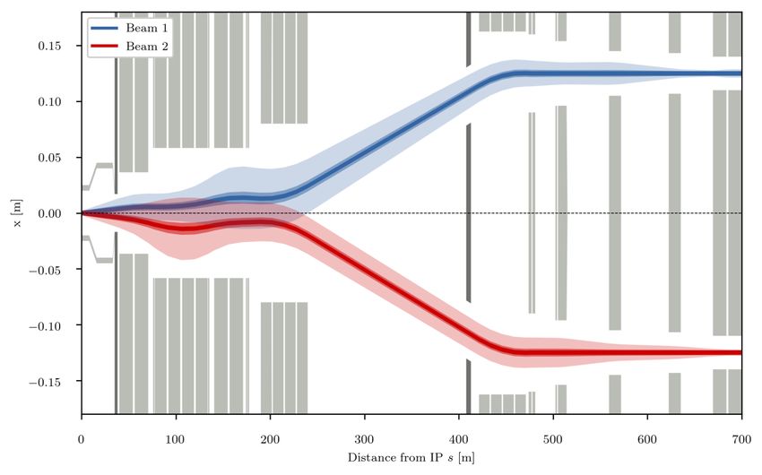
Figure 2: High luminosity EIR apertures. Magnets are depicted in light gray, absorbers in dark gray. At sEIR KEY COMPONENT FUNCTIONAL EuroCirCol-P3-WP3-M3.4
DESIGN SPECIFICATIONS FOR Date: 30/07/2018
PRELIMINARY BASELINE
2.2. EXPERIMENTAL CAVERNS AND TUNNEL
The dimensions of the experimental caverns are governed by the needs of the experiments. A cavern
length of 66 m is required for the opening of the detectors. Apart from the beam pipe, no accelerator
elements are currently foreseen to be placed inside the cavern.
For the HL-LHC, caverns housing the klystron galleries are foreseen few meters above the crab
cavities. For the baseline FCC-hh design, similar cavities will be required. No further details on
requirements of technical galleries, access galleries or similar infrastructure have been collected so far.
2.3. POWER SUPPLIES
At this point, only a general estimates of the magnet power supplies can be given. In the case of the
matching quadrupoles it is safe to assume that all magnets and both apertures per magnet are
individually powered. The exception is Q7 (MQM magnet family) which consists of two submagnets
due to length constraints. Consequently 56 matching quadrupole power supplies are required in
total for all the matching sections. Specifications of the power supplies like current and power
cannot be given at this point.
In the case of the triplets and separation/recombination magnets the technical details have not yet
been addressed. It should e.g. be possible to power the D1/D2 dipoles together with a single power
supply. Similarly, a single triplet could have a single main power supply but this would require
additional trim power supplies. Additionally both triplets of one IP could be powered together.
Further power supplies will be required for orbit correctors and non-linear corrector magnets close to
the triplets in the high luminosity EIRs. Seeing that the single aperture orbit correctors have nested
coils while the double aperture orbit correctors have two independently powered apertures, a total of
116 orbit corrector power supplies.
For the non-linear and skew correctors 32 power supplies are foreseen.
Grant Agreement 654305 PUBLIC 8 / 11EIR KEY COMPONENT FUNCTIONAL EuroCirCol-P3-WP3-M3.4
DESIGN SPECIFICATIONS FOR Date: 30/07/2018
PRELIMINARY BASELINE
3. CONCLUSIONS
Specification for the magnets in the EIRs are provided, together with the required numbers, not
including spares or replacements. Estimates for the expected replacements of the triplet magnets are
given. Requirements for the crab cavities are provided in terms of crab cavity voltage.
The machine relevant machine-detector interface is currently limited to the detector beam pipe and
absorbers. The energy deposition from collision debris on the absorbers and cold mass requires an
adequate cooling system.
The experimental cavern layout is given by the detector design, no requirements from the machine are
imposed. However the crab cavities are expected to require galleries for the klystrons, similar to HL-
LHC.
First estimates for the minimum number of magnet power supplies and beam position monitors are
provided.
Grant Agreement 654305 PUBLIC 9 / 11EIR KEY COMPONENT FUNCTIONAL EuroCirCol-P3-WP3-M3.4
DESIGN SPECIFICATIONS FOR Date: 30/07/2018
PRELIMINARY BASELINE
4. REFERENCES
Baseline triplet magnets, crab cavity voltage:
R. Martin et al., “Experimental Insertions”, FCC week 2018,
https://indico.cern.ch/event/656491/contributions/2923542/
Alternative triplet magnets:
Jose Abelleira et al., “Flat beam alternative”, FCC week 2018,
https://indico.cern.ch/event/656491/contributions/2930727/
Energy deposition, heat load and survivable dose:
F. Cerutti et al., “Beam loss studies in IP”, FCC week 2018,
https://indico.cern.ch/event/656491/contributions/2930726/
Low luminosity IR:
M. Hofer et al., “3.3 TeV beam injection into combined experimental and injection FCC
machine insertions”, FCC week 2017,
https://indico.cern.ch/event/556692/contributions/2484269/
Grant Agreement 654305 PUBLIC 10 / 11EIR KEY COMPONENT FUNCTIONAL EuroCirCol-P3-WP3-M3.4
DESIGN SPECIFICATIONS FOR Date: 30/07/2018
PRELIMINARY BASELINE
5. ANNEX GLOSSARY
SI units and formatting according to standard ISO 80000-1 on quantities and units are used throughout
this document where applicable.
ATS Achromatic Telescopic Squeezing
BPM Beam Position Monitor
c.m. Centre of Mass
DA Dynamic Aperture
DIS Dispersion suppressor
ESS Extended Straight Section
FCC Future Circular Collider
FCC-ee Electron-positron Collider within the Future Circular Collider study
FCC-hh Hadron Collider within the Future Circular Collider study
FODO Focusing and defocusing quadrupole lenses in alternating order
H1 Beam running in the clockwise direction in the collider ring
H2 Beam running in the anti-clockwise direction in the collider ring
HL-LHC High Luminosity – Large Hadron Collider
IP Interaction Point
IR Interaction Region
LHC Large Hadron Collider
LLIR Low Luminosity Interaction Region
LAR Long arc
LSS Long Straight Section
MBA Multi-Bend Achromat
MIR Main Interaction Region
Nb3Sn Niobium-tin, a metallic chemical compound, superconductor
Nb-Ti Niobium-titanium, a superconducting alloy
RF Radio Frequency
RMS Root Mean Square
σ RMS size
SAR Short arc
SR Synchrotron Radiation
SSC Superconducting Super Collider
TSS Technical Straight Section
Grant Agreement 654305 PUBLIC 11 / 11You can also read