Andreas Streun Paul Scherrer Institut (PSI) Villigen, Switzerland Future Research Infrastructures: Challenges and Opportunities Varenna, Italy ...
←
→
Page content transcription
If your browser does not render page correctly, please read the page content below
Andreas Streun
       Paul Scherrer Institut (PSI) Villigen, Switzerland

Future Research Infrastructures: Challenges and Opportunities
               Varenna, Italy, July 8-11, 2015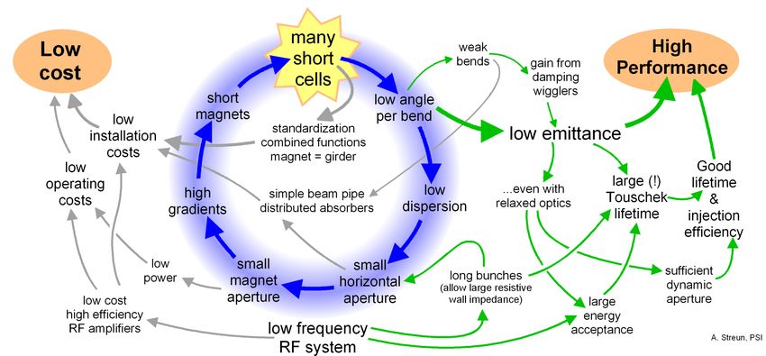
Outline

      Portrait of the SLS; history and achievements
      The new generation of light sources
      The challenge to upgrade the SLS
      A new type of lattice cell for lower emittance:
      longitudinal gradient bends and anti-bends
      SLS-2 design: performance, challenges, highlights

A. Streun, PSI   Swiss Light Source: the next 20 years, Varenna, July 10, 2015   2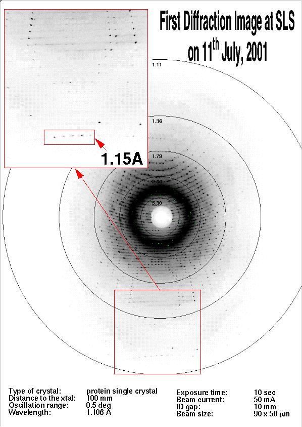
Paul Scherrer Institut (PSI)
1960 Eidgenössisches Institut für Reaktorforschung (EIR)
1968 Schweizer Institut für Nuklearphysik (SIN)
1988 EIR + SIN = PSI research with photons, neutrons, muons
PSI Accelerators:
590 MeV proton cyloctron: 1.3 MW beam power
spallation neutron source SINQ & muon source SmS
5.8 GeV / 1 Å free electron laser SwissFEL: operation 2017
2.4 GeV synchrotron light source SLS
A. Streun, PSI Swiss Light Source: the next 20 years, Varenna, July 10, 2015 3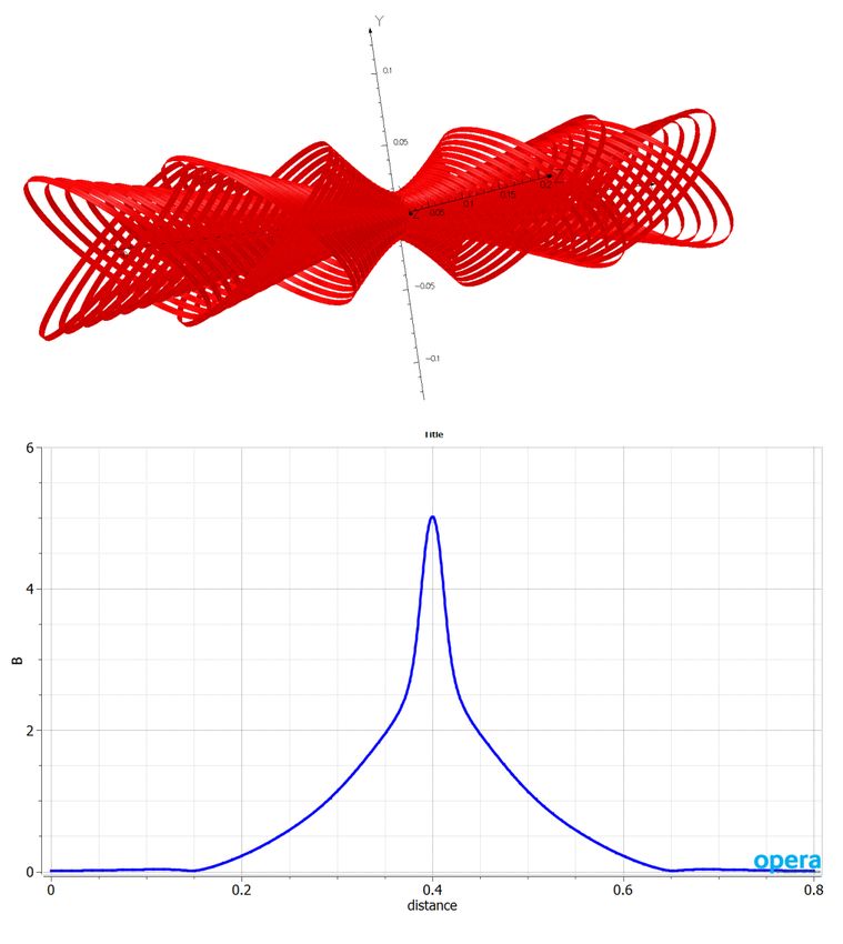
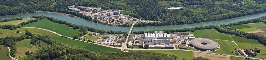
The SLS
Electron beam cross
section in comparison
transfer lines to human hair
90 keV
pulsed (3 Hz)
thermionic 100 MeV
electron gun pulsed linac
Synchrotron (“booster”) Current vs. time
100 MeV 2.4 [2.7] GeV
within 146 ms (~160’000 turns)
2.4 GeV storage ring
ex = 5.0..6.8 nm, ey = 1..10 pm 1 mA
400±1 mA beam current
top-up operation
4 days
shielding
walls
A. Streun, PSI Swiss Light Source: the next 20 years, Varenna, July 10, 2015 4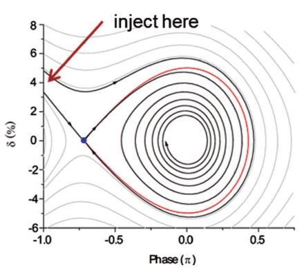
SLS: beam lines overview

A. Streun, PSI   Swiss Light Source: the next 20 years, Varenna, July 10, 2015   5
SLS: history

                 1990   First ideas for a
                        Swiss Light Source
                 1993   Conceptual Design Report
    June         1997   Approval by Swiss Government
    June         1999   Finalization of Building
    Dec. 2000 First Stored Beam
    June         2001   Design current 400 mA reached
                        Top up operation started
    July         2001 First experiments
    Jan.         2005   Laser beam slicing “FEMTO”
    May          2006   3 Tesla super bends
                 2010   ~completion: 18 beamlines

A. Streun, PSI           Swiss Light Source: the next 20 years, Varenna, July 10, 2015   6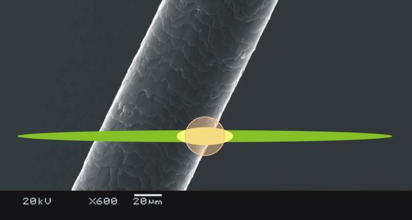
SLS achievements
Rich scientific output
> 500 publications in refereed journals/year
four spin-off companies (e.g. DECTRIS)
Reliability
5000 hrs user beam time per year
97.3% availability (2005-2014 average)
Top-up operation since 2001
constant beam current 400-402 mA over many days
Photon beam stability < 1 mm rms (at frontends)
fast orbit feedback system ( < 100 Hz )
undulator feed forward tables, beam based alignment,
dynamic girder realignment , photon BPM integration etc...
Ultra-low vertical emittance: 0.9 ± 0.4 pm
model based and model independent optics correction
high resolution beam size monitor developments
150 fs FWHM hard X-ray source FEMTO
laser-modulator-radiator insertion and beam line
A. Streun, PSI Swiss Light Source: the next 20 years, Varenna, July 10, 2015 7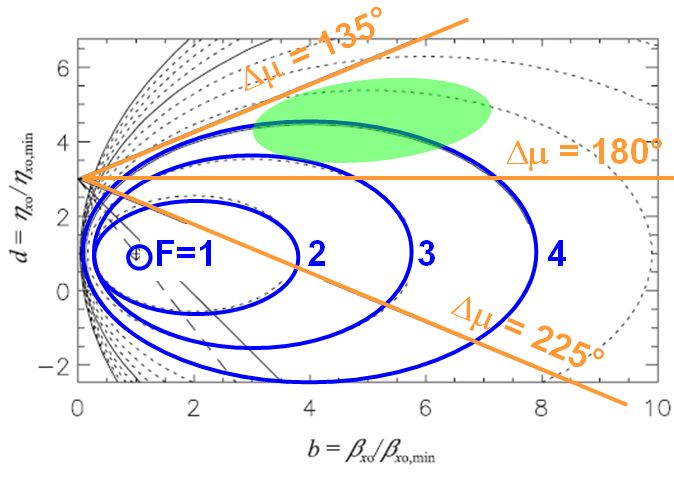
Horizontal emittance normalized to beam energy
The storage ring generational change
energy 2
emittance
circumference3
Riccardo Bartolini (Oxford University)
4th low emittance rings workshop,
Frascati , Sep. 17-19, 2014
Storage rings in operation (•) and planned (•).
The old (—) and the new (—) generation.
A. Streun, PSI Swiss Light Source: the next 20 years, Varenna, July 10, 2015 8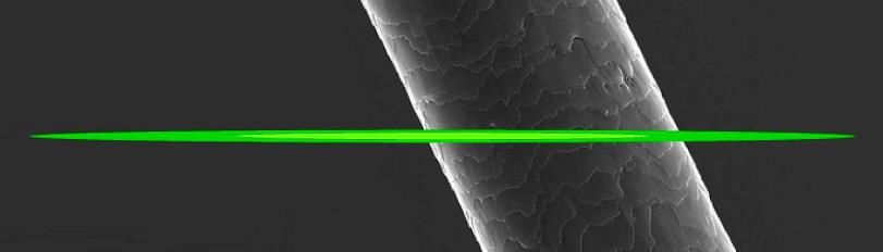
New storage rings and upgrade plans
Name Energy [GeV] Circumf. [m] Emittance* [pm] Status
PETRA-III 6.0 2304 4400 1000 operational
3.0 85 (round beam)
MAX-IV 3.0 528 328 200 2015
SIRIUS 3.0 518 280 2016
ESRF upgrade 6.0 844 147 2020
DIAMOND upgrade 3.0 562 275 started
APS upgrade 6.0 1104 65 study
SPRING 8 upgrade 6.0 1436 68 study
PEP-X 4.5 2200 29 10 study
ALS upgrade 2.0 200 100 study
ELETTRA upgrade 2.0 260 250 study
SLS now 2.4 288 5020** operational
SLS-2 2.4 (?) 288 100-200 ? 2024 ?
*Emittance without with damping wigglers **without FEMTO insertion
A. Streun, PSI Swiss Light Source: the next 20 years, Varenna, July 10, 2015 9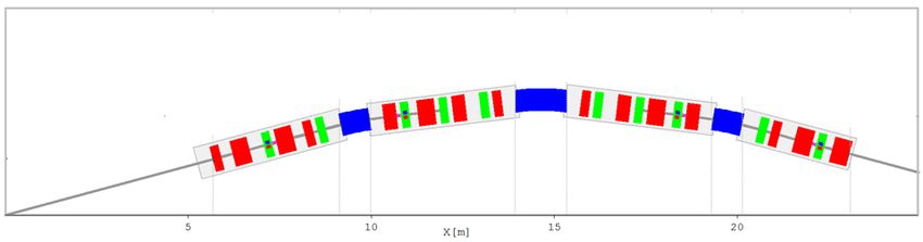
The Multi-Bend Achromat (MBA) Miniaturization small vacuum chambers [NEG coated] high magnet gradients more cells in given circumference A. Streun, PSI Swiss Light Source: the next 20 years, Varenna, July 10, 2015 10
SLS upgrade constraints and challenges
Constraints
get factor 20...50 lower emittance (100...250 pm)
keep circumference & footprint: hall & tunnel.
re-use injector: booster & linac.
keep beam lines: avoid shift of source points.
“dark period” for upgrade 6...9 months
Main challenge: small circumference (288 m)
Multi bend achromat: e (number of bends)─3
ring
Damping wigglers (DW): e ring + DW radiated power
Low emittance from MBA and/or DW requires space !
Scaling MAX IV to SLS size and energy gives e 1 nm
New lattice concept e 100...200 pm
A. Streun, PSI Swiss Light Source: the next 20 years, Varenna, July 10, 2015 11Theoretical minium emittance (TME) cell dilemma
Conditions for minimum emittance (h = 1/r = eB/p curvature)
L hL2 7.8 (f [ o 3
])
b omin = homin = e xo [pm rad] =
min
( E[GeV]) 2
2 15 24 12 15 Jx
periodic/symmetric cell: b ’ = h’ = 0 at ends
over-focusing of bx phase advance m min =284.5°
2nd focus, useless 16
0.08
0.06
overstrained optics, Betafunctions [m]
14 0.04
0.02
Dispersion [m]
12 0.00
huge chromaticity... 10
bx by h
-0.02
-0.04
-0.06
8
long cell 6
4
-0.08
-0.10
-0.12
better have two
-0.14
2 -0.16
-0.18
relaxed cells of f/2
0
0 1 2 3 4 5 6
f, L, h
MBA concept...
A. Streun, PSI Swiss Light Source: the next 20 years, Varenna, July 10, 2015 12Conventional cells = relaxed TME cells
Deviations from
TME conditions
e xo bo ho
F = min b = min d = min
e xo bo ho
Ellipse equations
for emittance
5
4 (d 1) (b F ) = F 1
2 2 2
Cell phase advance
m 6 b
tan =
2 15 (d 3)
Real cells: m < 180° F ~ 3...6 MBA: F > 10
A. Streun, PSI Swiss Light Source: the next 20 years, Varenna, July 10, 2015 13how to do better ?
1. disentangle dispersion h and beta function bx
release constraint: focusing is done with quads only.
use “anti-bend” (AB) out of phase with main bend
suppress dispersion (ho 0) in main bend center.
allow modest bxo for low cell phase advance.
2. optimize bending field for minimum emittance
release constraint: bend field is homogeneous.
use “longitudinal gradient bend” (LGB)
highest field at bend center (ho = (e/p) Bo)
reduce field h(s) as dispersion h(s) grows
sub-TME cell (F < 1) at moderate phase advance
A. Streun, PSI Swiss Light Source: the next 20 years, Varenna, July 10, 2015 14step 1: the anti-bend (AB)
General problem of dispersion matching:
– dispersion is a horizontal trajectory
– dispersion production in dipoles “defocusing”: h’’ > 0
Quadrupoles in conventional cell: dispersion:
anti-bend
– over-focusing of beta function bx off / on
– insufficient focusing of dispersion h
disentangle h and bx
bx by
use negative dipole: anti-bend
– kick Dh’ = , angle < 0
– out of phase with main dipole
– negligible effect on bx , by relaxed TME cell, 5°, 2.4 GeV, Jx 2
Emittance: 500 pm / 200 pm
A. Streun, PSI Swiss Light Source: the next 20 years, Varenna, July 10, 2015 15I 4 = bh (bAB
2
2emittance
k ) ds I 2 effects
J x = 1 II 42 2
AB emittance contribution
h 2
Disp. h
e I 5 = | h |3 H ds
AB
| h |3 L
L b bx by
– h is large and constant at AB
low field, long magnet
Cell emittance (2AB +main bend)
– main bend angle to be increased by 2| |
in total, still lower emittance
AB as combined function magnet
– Increase of damping partition Jx
• vertical focusing in normal bend
• horizontal focusing in anti-bend.
– horizontal focusing required anyway at AB
AB = off-centered quadrupole half quadrupole
A. Streun, PSI Swiss Light Source: the next 20 years, Varenna, July 10, 2015 16I 4 = bAB
h (b 2impact
2k ) ds I J =
on chromaticity
2 x 1 I2 2
I4
Anti-bend negative momentum compaction a
small large
1
a = hh ds hh ds < 0
C LGB AB negative
Head-tail stability for negative chromaticity!
side note: AB history
1980’s/90’s: PAC 1989
proposed for
isochronous rings
and to increase
damping - but
A. Streun, PSI Swiss Light Source: the next 20 years, Varenna, July 10, 2015 17step 2: the longitudinal gradient bend (LGB)
e I 5 = | h ( s ) | H ( s ) ds 3
L
h 2 (ah bh ' ) 2
Dispersion’s betatron amplitude H =
b
Orbit curvature h(s) = B(s)/(p/e)
Longitudinal field variation h(s) to compensate H (s) variation
Beam dynamics in bending magnet
– Curvature is source of dispersion: h ' ' ( s ) = h( s ) h ' ( s ) h ( s )
1a 02
– Horizontal optics ~ like drift space: b ( s ) = b 0 2a 0 s b0 s2
– Assumptions: no transverse gradient (k = 0); rectangular geometry
Variational problem: find extremal of h(s) for
I 5 = f ( s,h ,h ' ,h ' ' ) ds min with functional f = H ( s,h ,h ' ,h ' ' ) | h ' ' |3
L
numerical optimization
A. Streun, PSI Swiss Light Source: the next 20 years, Varenna, July 10, 2015 18LGB numerical optimization
Half bend in N slices: Results for half symmetric bend
( L = 0.8 m, F = 8°, 2.4 GeV )
curvature hi , length Dsi
optimized
Knobs for minimizer: hyperbola fit
{hi}, b0, h0
homogeneous
Objective: I5
Constraints:
I
length: SDsi = L/2
angle: ShiDsi = F/2
[ field: hi < hmax ] I5 contributions
[ optics: b0 , h0 ]
Results:
hyperbolic field variation
(for symmetric bend, dispersion suppressor bend is different)
Trend: h0 , b0 0 , h0 0
A. Streun, PSI Swiss Light Source: the next 20 years, Varenna, July 10, 2015 19LGB optimization with optics constraints
Numerical optimization of field profile for fixed b0, h0
Emittance (F) vs. b0, h0 normalized to data for TME of hom. bend
F=1
F 0.3 F=1
small (~0) dispersion at centre required, but tolerant to large beta function
A. Streun, PSI Swiss Light Source: the next 20 years, Varenna, July 10, 2015 20The LGB/AB cell
Conventional cell vs. longitudinal-gradient bend/anti-bend cell
both: angle 6.7°, E = 2.4 GeV, L = 2.36 m, Dmx = 160°, Dmy = 90°, Jx 1
conventional: e = 990 pm (F = 3.4) LGB/AB: e = 200 pm (F = 0.69)
Disp. h Disp. h
bx by bx by
dipole field longitudinal
quad field
} at R = 13 mm gradient anti-bend
total |field|
bend
A. Streun, PSI Swiss Light Source: the next 20 years, Varenna, July 10, 2015 21SLS-2 lattice layout
TBA 7BA lattice: ½ + 5 + ½ cells of LGB/AB type
periodicy 3: 12 arcs and 3 different straight types:
6 4 m 6 2.9 m 3 7 m 3 5.1 m
split long straights: 3 11.5 m 6 5.1 m
beam pipe: 64 mm x 32 mm 20 mm
magnet aperture 26 mm
A. Streun, PSI Swiss Light Source: the next 20 years, Varenna, July 10, 2015 22SLS-2 lattice db02l (one superperiod = 1/3 of ring)
optics and magnetic field
(field at poletips for R = 13 mm)
Superbends in arcs 2/6/10
3 2.9 T 3 5.0 T
A. Streun, PSI Swiss Light Source: the next 20 years, Varenna, July 10, 2015 23SLS-2 lattice parameters Name SLS*) db02l fa01f status operating baseline fallback Emittance at 2.4 GeV [pm] 5022 137 262 Lattice type TBA 7BA 5BA Total absolute bending angle 360° 585° 488° Working point Qx/y 20.42 / 8.74 38.38 / 11.28 28.29 / 10.17 Natural chromaticities Cx/y 67.0 / 19.8 67.5 / 36.0 64.1 / 39.9 Optics strain1) 7.9 5.6 8.9 Momentum compaction factor [104 ] 6.56 1.39 1.86 Dynamic acceptance [mm.mrad] 2) 46 10 17 Radiated Power [kW] 3) 205 228 271 rms energy spread [103 ] 0.86 1.05 1.15 damping times x/y/E [ms] 9.0 / 9.0 / 4.5 4.5 / 8.0 / 6.4 5.0 / 6.8 / 4.1 1) product of horiz. and vert. normalized chromaticities C/Q 2) max. horizontal betatron amplitude at stability limit for ideal lattice 3) assuming 400 mA stored current, bare lattice without IDs *) SLS lattice d2r55, before FEMTO installation (
Non-linear optimization
13 sextupole & 10 octupole families
step 1: perturbation theory: insufficient
1st & 2nd order sextupole terms
1st order octupole terms
up to 3rd order chromaticities
step 2: multi-objective genetic optimizer
objectives: dynamic aperture at Dp/p = 0, 3%
contraints: tune fooprint within ½ integer box
Lattice acceptance results (ideal lattice)
horizontal acceptance 10 mm·mrad
sufficient for off-axis multipole injection
from existing booster synchrotron
Touschek lifetime 3.2 hrs
1 mA/bunch, 10 pm vertical emittance, 1.43 MV overvoltage
further increase to 7-9 hrs by harmonic RF system.
A. Streun, PSI Swiss Light Source: the next 20 years, Varenna, July 10, 2015 25More challenges... work just started
Collective effects
large resistive wall impedance ( aperture3)
low momentum compaction factor |a|, and a < 0
close thresholds for turbulent bunch lengthening
head-tail stability for chromaticity 0
intrabeam scattering 15-30% emittance increase
Alignment tolerances
common magnet yoke = girder
initial mechanical alignment will be insufficient
extensive use of beam based alignment methods
longer commissioning than 3rd gen. light source
A. Streun, PSI Swiss Light Source: the next 20 years, Varenna, July 10, 2015 26Advanced options
Round beam scheme
Wish from users (round samples...) SLS
Maximum brightness & coherence SLS-2
SLS-2 RB
Mitigation of intrabeam scattering blow-up
“Möbius accelerator”:
beam rotation on each turn to exchange
transverse planes
Figure taken from R. Hettel, JSR 21 (2014) p.843
A new on-axis injection scheme
cope with reduced aperture
(physical or dynamic)
interplay of radiation damping and
synchrotron oscillation forms attractive
channel in longitudinal phase space for
off-energy off-phase on-axis injection.
A. Streun, PSI Swiss Light Source: the next 20 years, Varenna, July 10, 2015 27Longitudinal gradient superbend
Photon energy range
Dipole Flux [ph/mr^2/sec/0.1%bw]
1.4 T
5.00E+13 2.95 T
4.00E+13
5.7 T
3.00E+13
2.00E+13
1.00E+13
0.00E+00
0 20 40 60 80 100
YBCO1) HTS2) tape in Courtesy
canted-cos-theta Ciro Calzolaio, PSI
configuration on
hyperbolic mandrel
hyperbolic field profile
open for radiation fan
> 5T peak field
1) Yttrium-Barium-Copper-Oxide
2) High Temperature Superconductor
A. Streun, PSI Swiss Light Source: the next 20 years, Varenna, July 10, 2015 28Time schedule
Jan. 2014 Letter of Intent submitted to SERI
(SERI = State secretariat for Education, Research and Innovation)
schedule and budget
• 2017-20 studies & prototypes 2 MCHF
• 2021-24 new storage ring 63 MCHF
beamline upgrades 20 MCHF
Oct. 2014
positive evaluation by SERI:
SLS-2 is on the “roadmap”.
Concept decisions fall 2015.
Conceptual design report end 2016.
A. Streun, PSI Swiss Light Source: the next 20 years, Varenna, July 10, 2015 29Summary
The Swiss Light Source is successfully in operation since 15 years...
...but progress in storage ring design enforces an upgrade.
Upgrade of the Swiss Light Source SLS has to cope with a rather
compact lattice footprint...
... but the new LGB/AB cell provides five times lower emittance than
a conventional lattice cell:
Anti bends (AB) disentangle horizontal beta and dispersion functions.
Longitudinal gradient bends (LGB) provide minimum emittance by
adjusting the field to the dispersion.
The baseline design for SLS-2 is a 12 7BA lattice providing 30-35
times lower emittance.
The design is challenged by non-linear optics optimization, beam
instabilities and correction of lattice imperfections.
A conceptual design report is scheduled for end 2016.
A. Streun, PSI Swiss Light Source: the next 20 years, Varenna, July 10, 2015 30Acknowledgements
Beam Dynamics:
Michael Ehrlichman, Ángela Saá Hernández,
Masamitsu Aiba, Michael Böge
Instabilities and impedances:
Haisheng Xu, Eirini Koukovini-Platia (CERN),
Lukas Stingelin, Micha Dehler, Paolo Craievich
Magnets:
Ciro Calzolaio, Stephane Sanphilippo,
Vjeran Vrankovic, Alexander Anghel
Vacuum system:
Andreas Müller, Lothar Schulz
General concept and project organisation:
Albin Wrulich, Lenny Rivkin, Terry Garvey, Uwe Barth
A. Streun, PSI Swiss Light Source: the next 20 years, Varenna, July 10, 2015 31You can also read