Certification of Radome Lightning Direct Effects Protection - IOPscience
←
→
Page content transcription
If your browser does not render page correctly, please read the page content below

Journal of Physics: Conference Series

PAPER • OPEN ACCESS

Certification of Radome Lightning Direct Effects Protection
To cite this article: Qin Fei and Wu Ying 2021 J. Phys.: Conf. Ser. 1759 012028

View the article online for updates and enhancements.

                               This content was downloaded from IP address 46.4.80.155 on 15/07/2021 at 13:47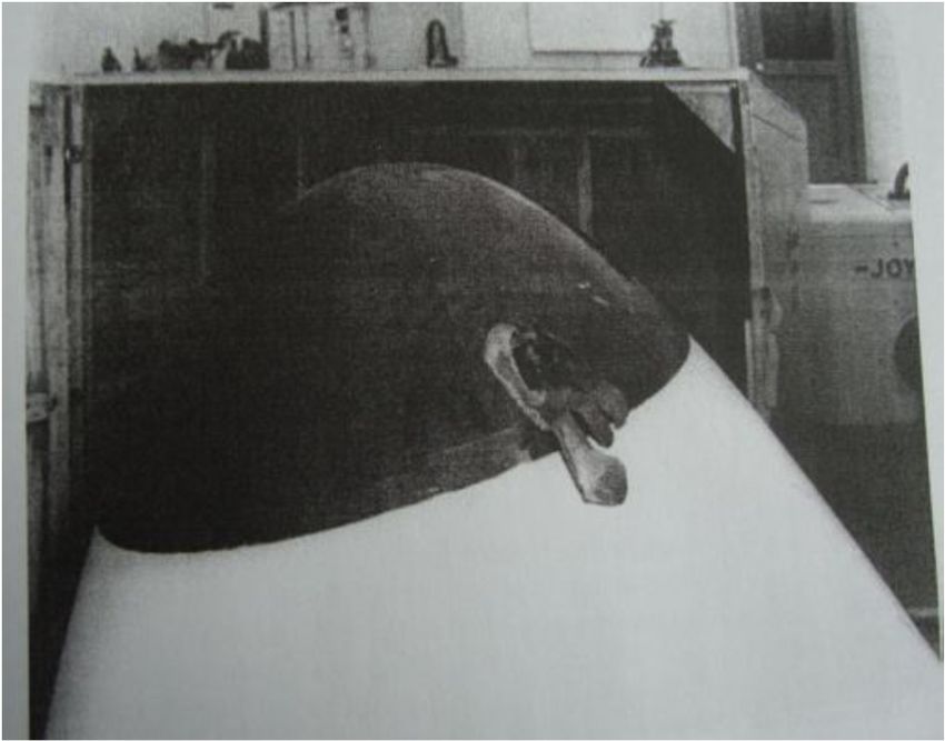
GCMN 2020                                                                                                       IOP Publishing
Journal of Physics: Conference Series                         1759 (2021) 012028          doi:10.1088/1742-6596/1759/1/012028

Certification of Radome Lightning Direct Effects Protection

                     Qin Fei1, a*, Wu Ying2,b
                     1
                      Shanghai Aircraft Design and Research Institute of COMAC , No.5188 Jinke Road,
                     Pudong New Area, Shanghai, PRC
                     2
                      Shanghai Aircraft Design and Research Institute of COMAC , No.5188 Jinke Road,
                     Pudong New Area, Shanghai, PRC
                     a
                         email: qinfei@comac.cc, bemail: wuying1@comac.cc

                     Abstract. Composite material is used more and more in airplanes year after year. The
                     electrical conductivity of composite material structure is poorer than metal structure, so
                     appropriate lightning protection measures should be adopted to shunt lightning current when
                     composite structure suffering lightning strike, and the harmful consequence will be minimized.
                     The paper takes radome as an example, which is located at nose area liable to suffer lightning
                     strike, introduces radome lightning protection measures, and according to lightning direct
                     effect verification process, discusses on means of compliance, plans high voltage strike
                     attachment test and high current physical damage test of radome. It provides reference for
                     airworthiness verification for radome.

1. Introduction
The aircraft radome is located at the front of the aircraft, and has a high probability of being struck by
lightning. In order to improve the survival ability of the aircraft in adverse weather environment,
lightning protection measures should be taken for the radome. When the radome is struck by lightning,
the lightning leader is attached to the lightning protection system, and the current is transmitted to the
airframe through the lightning protection system to release the radome and its interior The avionics
equipment plays a protective role. Taking radome as an example, this paper discusses the
airworthiness compliance verification method.

2. Background
In 1940, for the first time in the world, military aircraft radomes were made of glass fiber reinforced
unsaturated polyester resin. From 1960s to 1970s, glass fiber reinforced plastic (GFRP) products have
been widely used in aviation industry. In this kind of composite, the amount of glass fiber is 30% ~
60%, and the matrix materials are mainly unsaturated polyester resin, epoxy resin and phenolic resin.
The specific strength (tensile strength / density) of GFRP is higher than that of steel, and its corrosion
resistance is better. Since then, lightweight carbon fiber and carbon fiber composites with high specific
strength and high specific modulus have also been developed. After carbon fiber, aromatic polyamide
fiber (aramid fiber) and other high-performance fibers have been developed. Such composites
represented by carbon fiber composites are called advanced composites materials (ACM).
    The aircraft may suffer from lightning stroke during flight. Table 1 lists the statistical data of
lightning accidents of various types of civil aircraft. From these data, it can be seen that on average,
the aircraft will suffer a lightning stroke every 3000 flight hours, that is, once a year [1]. Therefore, in
order to ensure flight safety, lightning protection must be considered in civil aircraft design. With the
              Content from this work may be used under the terms of the Creative Commons Attribution 3.0 licence. Any further distribution
              of this work must maintain attribution to the author(s) and the title of the work, journal citation and DOI.
Published under licence by IOP Publishing Ltd                          1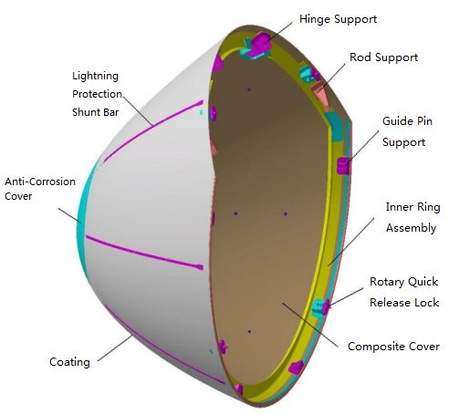
GCMN 2020                                                                                    IOP Publishing
Journal of Physics: Conference Series           1759 (2021) 012028     doi:10.1088/1742-6596/1759/1/012028

increase of composite materials used in modern civil aircraft, lightning protection design for non-
conductive composite structures is particularly important. Take the radome as an example, its
structural integrity can effectively protect the radar antenna from the impact of the external
environment of the aircraft, such as aerodynamic load, rain, static electricity, lightning, hail, bird strike
or other impacts. Figure 1 shows the glass fiber honeycomb radome broken down by lightning.
Reasonable lightning protection design can avoid such phenomenon. For civil aircraft, it is necessary
to verify the airworthiness of lightning protection design to ensure flight safety. In this paper, taking
radome as an example, the certification method of structural lightning protection design is discussed.

                          Table.1 Statistics of civil aircraft lightning accidents
                            Number of Lightning                                      Flight Hours per
       Aircraft Type                                      Flight Hours
                                 Strokes                                             Lightning Stroke
        Piston Type                808                      2000000                        2475
       Propeller Type              389                      1291000                        3320
          Jet Type                 521                      1741000                        3340
           Total                  1718                      5032000                        2930

                                 Figure.1 Radome Damaged by Lightning

3. Airworthiness Requirements
CCAR 25.581 provides relevant requirements for lightning protection of aircraft structure.
    CCAR 25.581 Lightning Protection
    (a) The airplane must be protected against catastrophic effects from lightning.
    (b) For metallic components, compliance with paragraph (a) of this section may be shown by-
    (1) Bonding the components properly to the airframe; or
    (2) Designing the components so that a strike will not endanger the airplane.
    (c) For nonmetallic components, compliance with paragraph (a) of this section may be shown by -
    (1) Designing the components to minimize the effect of a strike; or
    (2)Incorporating acceptable means of diverting the resulting electrical current so as not to
endanger the airplane.
    For lightning protection, 25.581 (a) provides the general requirements, that is, in order to prevent
catastrophic consequences caused by lightning, relevant protection measures must be considered in
aircraft design; for metal components, its conductivity is relatively good, generally intact electrical
bonding can ensure good lightning protection effect, and the value of lap resistance should be less than
50m Ω; for non-metallic components, 25.581 (c) mentions to minimize the consequences of flashover,
there is no quantitative concept, but it should at least ensure that no catastrophic consequences will
occur. At the same time, acceptable diversion measures should also ensure the safety of the aircraft.

                                                      2
GCMN 2020 IOP Publishing
Journal of Physics: Conference Series 1759 (2021) 012028 doi:10.1088/1742-6596/1759/1/012028
4. Radome Compliance Verification
The direct effect of lightning is the physical effect caused by the direct attachment of lightning channel
to aircraft and/or lightning current conduction on aircraft and/or equipment. This includes perforation,
bursting, bending, melting, burning and vaporization of insulators on aircraft and equipment
surfaces/structures. It also includes direct injection of voltage and current by lightning on
corresponding lines, pipelines and other conductive parts. Possible injuries to personnel include shock
effect and glare/blindness caused by strong flash.
Generally speaking, in order to show the aircraft's compliance with the direct effects of lightning,
the applicant will generally carry out six compliance activities. These compliance activities are an
iterative process, as shown in Figure 2. The six activities are as follows:
(1) Determine the lightning strike zones for aircraft;
(2) Establish the lightning environment associated with the zones;
(3) Perform Lightning Hazard Assessment. Determine aircraft structure, systems and components
safety classifications and make a Lightning Hazard Assessment to review the design of the aircraft and
its systems and components to identify lightning direct effects and their potential hazards;
(4) Design protection in accordance with acceptance criteria;
(5) Verify Compliance;
(6) Determine and implement corrective measures [2].
Figure.2 Compliance Route of Direct Lightning Effect
4.1. Determine the Lightning Strike Zones for Aircraft
Not all voltage waveforms and current components of the external lightning environment are
applicable to every part of the aircraft. The lightning zoning is convenient to match the aircraft
position with the external lightning environment. The location of these areas depends on the geometry
3GCMN 2020 IOP Publishing
Journal of Physics: Conference Series 1759 (2021) 012028 doi:10.1088/1742-6596/1759/1/012028
and operational parameters of the aircraft and varies with aircraft model. Therefore, a set of lightning
zones must be established for each aircraft model. Generally speaking, there are 1A, 1B, 1C, 2A, 2B
and 3. SAE ARP5414 gives the definition of each lightning zone and the determination method of
lightning zoning. The applicant can determine the lightning zoning by comparing with the existing
similar design, or through service experience or test method. The typical lightning stroke zoning of
civil aircraft is shown in Figure 3. It can be seen from the figure that the radome is located in zone 1A,
which is the area with high initial lightning attachment probability.
Figure.3 Typical Lightning Stroke Zoning of Civil Aircraft
4.2. Establish The Lightning Environment Associated with The Zones
There are two ways to express the external lightning environment, one is the composite waveform of
lightning current component on the aircraft surface, and the other is the voltage waveform which can
represent the relevant electric field effect before lightning attachment. According to SAE ARP5412,
the voltage waveform of radome in area 1A adopts D waveform (as shown in Fig. 4). The leading edge
time of voltage waveform D is 50 ~ 250 μ S, the actual output voltage amplitude is at least 1500kV.
The current waveform adopts current components A and B (as shown in Fig. 5) and is injected in the
form of composite components. The current component A waveform can be oscillatory or
unidirectional. The current amplitude is 200kA ± 10%, the maximum rise time (between the peak
value of 10% and 90%) is 50 μ s, the action integral is and the action time (to the
peak value 1%) are not more than 500 μ S. the waveform of current component B must be
unidirectional, with an average amplitude of 2kA ± 20%, pulse width of 5ms ± 10%, and coulomb of
10C ± 10% [3].
4GCMN 2020 IOP Publishing
Journal of Physics: Conference Series 1759 (2021) 012028 doi:10.1088/1742-6596/1759/1/012028
Figure.4 Voltage Waveform D
Figure.5 Schematic Diagram of Current Component A and B
Voltage waveform and current waveform are used for lightning attachment point test and lightning
current test respectively.
4.3. Perform Lightning Hazard Assessment
All aircraft structures must be evaluated for the effects of lightning to determine any hazardous
consequences that may be caused by lightning. Through the assessment, it should be determined
whether the structural failure or failure caused by lightning is likely to cause catastrophic
5GCMN 2020 IOP Publishing
Journal of Physics: Conference Series 1759 (2021) 012028 doi:10.1088/1742-6596/1759/1/012028
consequences immediately (or after a certain delay). According to the safety assessment, all aircraft
structures identified as lightning related must show compliance with the requirements of lightning
protection regulation 25.581.
The lightning safety classification of aircraft structures can refer to the classification of aircraft
structures in damage tolerance and fatigue assessment, focusing on the main structural parts (PSE).
According to AC25.571-1C, the main structural member (PSE) plays a major role in carrying flight
load, ground load or pressurization load. The radome is located at the front of the aircraft. Although it
is a non-PSE part, its structural integrity can effectively protect the radar antenna from the impact of
the external environment of the aircraft, such as aerodynamic load, rain, static electricity, lightning,
hail, bird strike or other impacts. The failure of radome may lead to disastrous consequences. It is
recognized that the radome needs to meet the lightning protection requirements. In order to ensure the
integrity of the radar antenna in the radome, the design criteria of the radome are that the structure is
intact and no parts fall off after lightning.
4.4. Design Protection in Accordance with Acceptance Criteria
Acceptable design schemes can be derived from existing design practices, design guidance or
previously verified manual data. For radome, measures should be taken to ensure that the non-
conductive surface can effectively shunt the lightning current. The typical lightning protection design
of radome achieves the purpose of shunting by setting lightning protection shunt bar on the outer
surface of radome, supplemented by appropriate lap joint.
The radome is composed of composite material cover, reinforcing frame, rainproof and antistatic
coating system, lightning protection system, metal joint and connector, anti-corrosion cover, quick
release lock, sealing ring, etc. Figure 6 shows the structure of radome.
Figure.6 Radome Structure
There are mainly two kinds of shunt bars on the surface of radome, one is solid aluminum strip, the
other is button type shunt strip. Solid aluminum strip is often used in civil aircraft, and the splitter bar
is fixed on the outer surface of radome with countersunk screw. The lightning protection system
consists of lightning protection shunt bar, reinforcement ring assembly and lap screw. After the
radome is equipped with lightning protection shunt bar, when the aircraft head is struck by lightning,
the lightning current can be released through the lightning protection shunt bar. The lightning current
conduction route is shown in Fig. 7.
6GCMN 2020 IOP Publishing
Journal of Physics: Conference Series 1759 (2021) 012028 doi:10.1088/1742-6596/1759/1/012028
Figure.7 Lightning Current Conduction Route
The main factors that affect the protection effect of radome lightning protection system are the
material of shunt bar, the size of cross-section of splitter strip, the arrangement of splitter bar interval,
etc. The selection of these main factors is usually preliminarily determined based on experience, and
then the rationality is verified by test, and the design parameters are adjusted as required until the
protection requirements are met.
4.5. Verify Compliance
The compliance verification needs to show that the structure can withstand the corresponding
Lightning Environment safely. It can be verified by similarity analysis, experiment, calculation
analysis or combination of several methods. Generally, new materials and new designs need to be
tested to verify compliance.
According to SAE ARP 5416, for radome located in zone 1A, it is necessary to implement the
radome lightning attachment point test and lightning current test[4], and use the voltage and current
waveform mentioned above. The lightning attachment point test is used to determine the lightning
attachment point and breakdown path of insulation material. The lightning current test is used to
determine the effect caused by lightning current flowing into the attachment point. The test can refer
to the following criteria,
(1) During lightning attachment point test, radome composite sandwich structure shall not be
perforated or layered.
(2) During the lightning current test, the lightning protection shunt bar or its connecting bolt on the
radome shall not fall off, but the shunt bar is allowed to deform locally; the hinge, quick release lock
and guide pin of the radome shall not be disconnected.
4.6. Determine and Implement Corrective Measures
According to the compliance verification results, if the acceptance criteria approved by authorities are
not met, the connection scheme between radome and fuselage, the connection form of metal parts and
the number and distribution of shunt bars shall be optimized and verified again until the requirements
are met.
5. Conclusion
According to the airworthiness requirements of direct lightning protection, the circumferential layout
and length of lightning protection shunt strip of radome should be reasonably designed. The lightning
leader should be attached to the lightning protection system first, and the current can be discharged
through the lightning protection system to ensure the safety of radome and its internal avionics
equipment. This paper discusses the verification method of lightning protection for radome, and
verifies the effectiveness of radome lightning protection design by planning lightning attachment point
test and lightning current test.
7GCMN 2020 IOP Publishing
Journal of Physics: Conference Series 1759 (2021) 012028 doi:10.1088/1742-6596/1759/1/012028
Acknowledgments
We would like to acknowledge the help of Shanghai Aircraft Design and Research Institute
and Chinese Aeronautical Establishment.
References
[1] DOT/FAA/CT-89/22. Aircraft Lightning Protection Mannual[S].2013.
[2] SAE ARP5577. Aircraft Lightning Direct Effects Certification[S].2008.
[3] SAE ARP5412. Aircraft Lightning Environment and Related Test Waveforms [S].2005.
[4] SAE ARP5416. Aircraft Lightning Test Methods[S].2005.
8You can also read