Design of C band antenna downlink system for monitoring Sentinel 1A signals on ground surface
←
→
Page content transcription
If your browser does not render page correctly, please read the page content below

Journal of Physics: Conference Series

PAPER • OPEN ACCESS

Design of C band antenna downlink system for monitoring Sentinel 1A
signals on ground surface
To cite this article: T R Manjula and K S Asha 2021 J. Phys.: Conf. Ser. 1854 012027

View the article online for updates and enhancements.

 This content was downloaded from IP address 46.4.80.155 on 16/07/2021 at 05:01
FEST 2020 IOP Publishing
Journal of Physics: Conference Series 1854 (2021) 012027 doi:10.1088/1742-6596/1854/1/012027

Design of C band antenna downlink system for monitoring
Sentinel 1A signals on ground surface

 T R Manjula1, K S Asha2
 1,2
 Electronics and Communication Engineering, SET, Jain University, Bangalore,
 India
 1
 hasiniskumar@gmail.com

 Abstract. The C band microwave signals are widely used for Earth observation in the
 field of remote sensing by using synthetic aperture radar sensor. The coverage of
 Indian regions by Sentinel 1A SAR sensor in interoferometric wide swath mode,
 provide an opportunity to research and conduct studies in remote sensing areas from
 urban planning to disaster management applications. The sensor acquired images
 undergo calibration test to confirm the quality requirements. The foremost significant
 step to ensure the availability of the signal of Sentinel 1A on the ground surface is by
 designing a antenna system which tracks and monitor the signal strength. In this
 context, the following stages are significant in signal monitoring system: satellite
 downlink budget calculation to ensure minimum signal strength, designing and
 configuring antenna system to receive the signals and measurement system such as
 spectrum analyser to monitor the signal strength. The paper presents the mathematical
 analysis of designing a down link for receiving Sentinel-1A SAR signals. An antenna
 subsystem is implemented which includes the design of the parabola antenna with
 horn feed and the simulation of the same using Matlab platform to confirm antenna
 parameters such as gain, directivity, VSWR and beam-width which meets the practical
 requirements

 Keywords: Sentinel 1A, Matlab, dish antenna, horn feed, spectrum analyser, signal strength

1. Introduction
With the advancements in satellite and sensor technology, the range and diversity of applications has
extended to various fields, predominantly in remote sensing areas, from meteorological and ocean
studies, the Earth observation and glacier monitoring to disaster management applications. The
satellite operating in microwave region is much like terrestrial link in Line of sight (LOS)
communication with a large coverage area. An Antenna system is designed and implemented to
monitor Sentinel 1A synthetic aperture radar (SAR) signals.
 The Satellite downlink budget [1] is a method to ensure the signal power on the ground surface is
greater than or equal to receiver sensitivity by accounting all types of losses during the course of
signal propagation from the transmitter to receiver as shown in the figure 1

 Content from this work may be used under the terms of the Creative Commons Attribution 3.0 licence. Any further distribution
 of this work must maintain attribution to the author(s) and the title of the work, journal citation and DOI.
Published under licence by IOP Publishing Ltd 1
FEST 2020 IOP Publishing
Journal of Physics: Conference Series 1854 (2021) 012027 doi:10.1088/1742-6596/1854/1/012027

 Let Pt be the power transmitted by the satellite. Due to spread of electromagnetic energy in the
course of propagation, an antenna is used to focus the energy in the desired direction or in the
direction of the receiver. The effective radiated power (EIRP) is the power radiated by the satellite
transmitter constituting a source and an antenna with gain Gt and is equal to product of Pt and Gt

 Figure 1. Schematic of satellite down link [13]

The power flux density ( ) at a distance R in the direction of maximum radiation is given by

 = watts/m2 (1)
 4 2

The receiving antenna with effective aperture Ae intercepts a fraction of the total power and the
received signal power PR is given by
 PR= ∗ (2)

 is the effective aperture area of the receiving antenna as given by
 2
 = 4
 (3)
and is related to the gain of the receiving antenna gain GR as
 4
 = 2 (4)
Therefore the received signal power by the antenna is given by

 2
 PR = 4 2 ∗ 4
 = 4 2 (5)
 ( )

 4 2
Where (
 ) is the free space path loss (FSPL)
In decibels, the received power
 PR= EIRP+GR-FSPL-AL-Ltxa-LRxa (6)
 In addition to FSPL, the other miscellaneous power losses include atmospheric losses (AL) and
antenna misalignment losses, transmitter and receiver antenna losses L txa and Lrxa respectively which
are taken into account by appropriate design margin typically 5-10dB.

 2
FEST 2020 IOP Publishing
Journal of Physics: Conference Series 1854 (2021) 012027 doi:10.1088/1742-6596/1854/1/012027

 The article aims to provide a detailed presentation on the design of satellite down link for remote
sensing satellite Sentinel 1A. It highlights on design efficiency of Parabola and horn antenna. The
simulation results using Matlab is presented to validate the requirements of antenna receiver.

2. Methodology

2.1. Analysis and design of satellite down link for Sentinel -1A at frequency f=5.405GHz

The table.1 lists the specifications of Sentinel 1A in order to compute power budget for down link and
estimate the received power on the ground surface

 Table.1: Specifications of Sentinel-1A (2)
 Parameters Specifications
 Centre frequency 5.405 GHz)
 Bandwidth 0-100 MHz
 Polarisation HH+HV, VV+VH, VV, HH
 Altitude 653Km
 Elevation angle 550
 Incidence angle range 20°- 46°
 Look direction right
 Antenna type Slotted waveguide radiators
 Azimuth beam width 0.23°
 Elevation beam width 3.43°
 - 4.368 kW, - 4.075 kW (IW, dual
 RF Peak power
 polarisations)
 Pulse width 5-100 µs (programmable)
 Transmit duty cycle IW 9%,
 Receiver noise figure at 3 dB
 module input
 Maximum range 100 MHz
 bandwidth
 PRF (Pulse Repetition 1 000 - 3 000 Hz (programmable)
 Frequency)

2.2. Free space path Loss
In order to compute free space path loss (FSPL), the slant range (R) [1] between the transmitter and
receiver is determined from the knowledge of Earth’s station elevation angle ( ), altitude (h) of the
Satellite as given by equation (7)
 ℎ+
 R= √
 + cos(θ)2 − sin(θ)2 (7)

Where h is the altitude, Re the radius of the Earth, θ is the elevation angle for Sentinel -1A altitude of
653 km, and elevation angle of 550, slant range obtained is equal to 785.676km and FSPL=165dB

 From the specifications of S-1A satellite signal as given in table 1, the received signal power on
the ground surface is calculated as given by equation. (6) Based on power budget calculation as
shown in the table.2, the signal power computed at the antenna input is - 59.38dBm. The signal

 3
FEST 2020 IOP Publishing
Journal of Physics: Conference Series 1854 (2021) 012027 doi:10.1088/1742-6596/1854/1/012027

power is enhanced with a antenna gain of 30dB to -29.38dBm which is well within the receiver
sensitivity. The receiver used for this application is a measurement system: spectrum analyser with
the dynamic range of -160dBm to +20dBm [3].

 Table.2: Link budget computation
 Sl. Parameters Specifications
 no
 1. Peak input power at antenna input (dBW) 36.17 dB
 2. Satellite antenna gain 43.5 dB
 3. Path loss 165dB
 4. Atmospheric loss 3dB
 5. Antenna loss (Ltxa & Lrxa) 0.7dB
 6. Received power at the antenna input -59.38dBm
 7. Receiving antenna gain +30dB
 8. Received signal at the spectrum analyser input -29.38dBm

2.3. Design consideration of dish antenna
The main objective is to design the receiving antenna with a gain of 30dB. This large gain is
achievable with parabola antenna which has primary feed and secondary reflector. Commonly, dish
antenna is chosen for high gain (30- 40dB) which is obtained by large aperture area and large
capturing capability. They are characterized to have high directivity and wide bandwidth. i.e., they
produce narrow beam. Typically the dimension of paraboloid is chosen larger than the wavelength
( ) of the signal used.
 In order to increase aperture efficiency [4] [5] [6], the dish is illuminated such that energy
illuminates uniformly upto the edge of the dish and drops off quickly beyond the edge. The energy at
the edges is 10dB lower than at the centre. Further, most of the noise received by an antenna pointed
at the sky is the Earth’s noise at 300K temperature rather than the noise from the sky. The pickup of
background noise can be reduced by reducing spill over efficiency. The dish and associated feed is
designed such that energy illumination covers only dish area and doesn’t spill over the edges as
shown in the figure 2.
 To achieve this, the dish is illuminated for 80% portion with drop of energy at the edges. This will
reduce taper efficiency and gain, but at the cost of improvement in SNR of the signal.

 Figure 2. Dish illumination with taper efficiency [12]

 4
FEST 2020 IOP Publishing
Journal of Physics: Conference Series 1854 (2021) 012027 doi:10.1088/1742-6596/1854/1/012027

 The parabola is defined by F/D ratio and typically varies from 0.25 to 0.65. For focal length (f)
equal to 60cm, F/D ratio obtained is 0.5. As F/D ratio becomes smaller, the feed pattern to illuminate
the dish becomes broader and is harder to illuminate efficiently. Further F/D ratio is the fundamental
factor governing the design of the feed for a dish. The ratio is directly related to beam width of the
feed necessary to illuminate the dish effectively. The smaller the ratio, lower the beam width and
smaller the side lobes.

 Table. 3: The Parabola antenna parameters
 Sl. Antenna Parameters Expression
 No
 1. Focal length 2
 f= 16
 2. Aperture angle 0 = 2 −1 ( )
 1
 4

 3. Antenna gain G=

 ( )2
 4. Beam width Bw=70 /

 Table. 4 : Design specifications of dish antenna for Gain=30dB

 Parameter Specifications
 Diameter(D) 120cm
 Depth (d) 15cm
 Focal length (f) 60cm
 F/D ratio 0.5
 Aperture angle 0 53.10
 Beam width 3.20

2.4. Design of horn feed for dish antenna
Sentinel-1A signals are vertical (V) and horizontal (H) polarized signals, to receive different
combinations of polarized signals (HH+HV, VV+VH, VV, HH), pyramidal horn antenna is chosen as
a feed for parabola antenna, as it is sensitive to V and H Polarization.

 Figure 3. Schematic of Pyramid horn antenna

 5
FEST 2020 IOP Publishing
Journal of Physics: Conference Series 1854 (2021) 012027 doi:10.1088/1742-6596/1854/1/012027

 A horn antenna is basically a waveguide (WG) with flaring at open ends as shown in the figure 3.
The function of the flare in the horn is to produce uniform phase front with larger aperture than that
of the WG and hence greater directivity. A WG excited at one end and open at other end radiates,
however due to mismatch between WG and free space impedance, the radiation is poor and results in
non directive radiation pattern. The open ends are flared out to improve radiation efficiency and
directivity. The type, direction and amount of flare have significant effect on the radiation
characteristics.
 The gain of 20 to 30 dB is achievable with Horns. The larger the aperture, larger is the directivity.
Hence the gain is directly proportional to length and area of horn. Horns are characterized to have
little loss and therefore widely used as standard gain antennas.
 To receive C band signals at a frequency of 5.405GHz signals, we chose standard waveguide
WR157 [7] [8] with dimensions: breadth (a) and width (b) as 4.038cm and 2.0193cm respectively. The
Cut- off wavelength = 8.076 and corresponding cutoff frequency fc= 3.7147GHz

2.4.1. Algorithm [9][10] to design pyramid horn antenna for gain of 15dB at frequency f=5.405GHz
For the desired gain G0, and basic dimension of the waveguide (‘a’ and ‘b’) of the rectangular
waveguide, the objective of the design is to determine the remaining dimensions A, B, , ℎ, RE and
RH of the horn as shown in the figure 4 and figure 5 by combining E and H plane that will lead to
optimum gain.

 Figure 4. Pyramid horn: E-plane Figure 5. Pyramid horn: H-plane view
 view

1: Find the initial value of zeta ( ) for the desired gain G0 given by

 0 G
 χ = 2π√2π (8)

2: For a pyramid horn antenna to be physically realizable R E and RH of E and H plane must be equal.
To achieve this, by trial and error method, is updated to satisfy the equation (9)

 3 1 2 1
 ( √2 − )2 (2 − 1) = (2 0 √2 − )2 (6 03 − 1) (9)
 √

3: After a few iteration a more accurate value of is determined for which the equation 13 is satisfied
4: Using equations 10 and 11 determine and ℎ

 = (10)
 ℎ 02 1
 = ( (11)
 8 3

 6
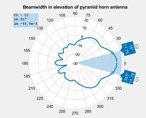
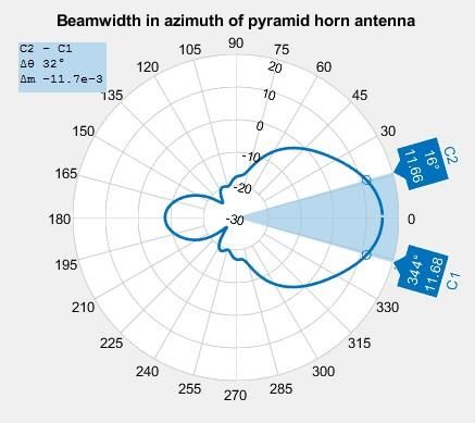
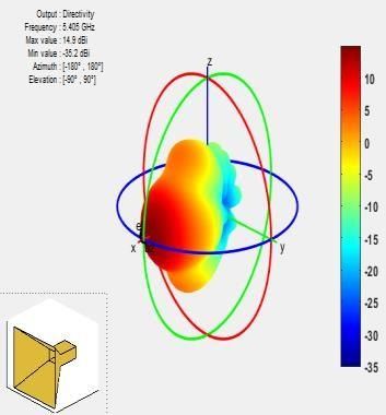
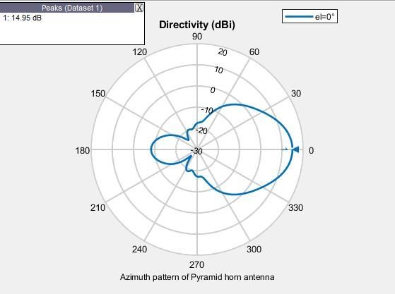
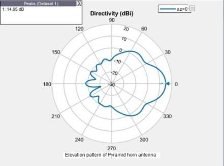
FEST 2020 IOP Publishing
Journal of Physics: Conference Series 1854 (2021) 012027 doi:10.1088/1742-6596/1854/1/012027

5: The corresponding values of A and B are given by equations

 =√3 ℎ (12)
 =√2 (13)
6: The values of RE and RH are determined using equations
 1
 RE=( − )[( )2 − ]2 (14)
 4
 1
 RH=( − )[( ℎ )2 − 4]2 (15)

 The algorithm is simulated using Matlab platform. The simulated pyramid horn antenna
 parameters are given in the table. 5.

 Table. 5: Designed pyramid horn antenna dimensions
 0.1021m
 ℎ 0.1216m
 A 0.1423m
 B 0.1065m
 RE 0.706m
 RH 0.706m

3. Results and Discussion
 The pyramid horn antenna is simulated using Matlab simulation platform. The beamwidth and
directivity in the azimuth and elevation direction is shown in the figure 6, 7, 8 and 9 respectively and
the beamwidth is equal to ~320

3.1. Matlab simulation results of pyramid horn antenna

 Figure 6. Azimuth Beam width Figure 7. Elevation Beam width

 Figure 8. Azimuth Directivity Figure 9. Elevation Directivity

 7
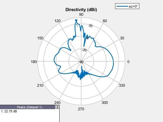
FEST 2020 IOP Publishing
Journal of Physics: Conference Series 1854 (2021) 012027 doi:10.1088/1742-6596/1854/1/012027

 Figure 10. Radiation pattern of pyramid horn Figure 11. Plot of VSWR

The radiation pattern and VSWR plot is shown in the figure 10 and 11 respectively. From the plot it is
evident the VSWR is desirably low at the operating frequency.

3.2.Matlab simulation results of Dish antenna with horn feed
The pyramid horn antenna is integrated with dish antenna to obtain dish antenna with horn feed.
The Matlab simulated dish antenna with horn feed is shown in the figure 12 and figure 13. The
directivity or gain is equal to ~22.8dB. From the plots of VSWR and return loss shown in the figure
14 and 15 respectively, it is evident the VSWR and return loss is appreciably low

 Figure 12. Directivity of Dish Figure 13.Radiation pattern of dish with pyramid horn
 antenna with pyramid horn feed feed at f=5.405GHz with directivity= 22.78dB

 Figure 14. VSWR for dish antenna Figure 15. Return loss for dish antenna

 8
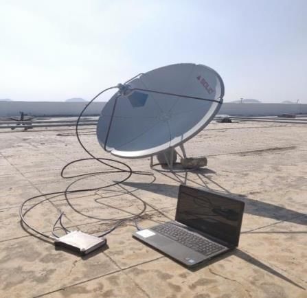
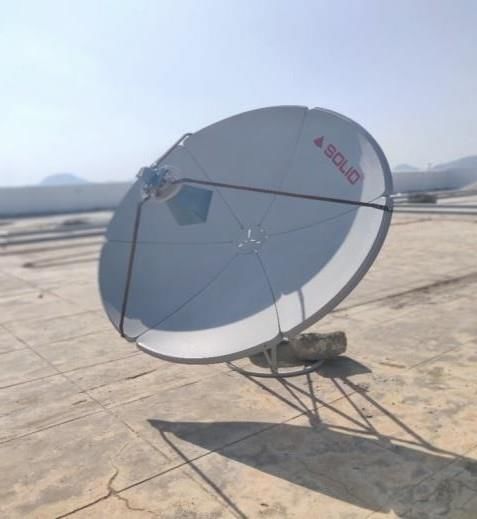
FEST 2020 IOP Publishing
Journal of Physics: Conference Series 1854 (2021) 012027 doi:10.1088/1742-6596/1854/1/012027

3.3. Experimental setup/Hardware implementation
The hardware antenna system setup deployed for monitoring Sentinel 1A SAR signals is shown in the
figure 16 and figure 17. It includes dish antenna with horn feed whose output is monitored on
spectrum analyser

Figure 16. Dish antenna with pyramid horn Figure 17. Antenna system with output connected
 feed to spectrum analyser

Conclusions
An antenna system is designed to monitor Sentinel 1A SAR signals on the ground surface. Link
budget calculation is vital to determine theoretically the minimum signal strength availability on the
ground surface by taking accountability of all possible losses during the course of propagation. The
antenna based system is designed to receive signals and monitor the strength, frequency, power and its
variability. Dish antenna with pyramid horn is designed for required specification and simulated in
Matlab and meets the gain requirement of 22dB, a low VSWR and return loss. Based on the design,
dish antenna hardware system is implemented to test the design.

Acknowledgments
Authors are thankful to SAC ISRO Respond team members and focal members for guidance and
support in various stages of the project phases. I acknowledge Dr. G Raju for his continuous support
and advice.

References
[1] Charles Bostian, Jeremy Allnutt, Timothy Pratt, Satellite communication, II edition, John
 Wiley & sons, 2006
[2] https://sentinels.copernicus.eu/web/sentinel/missions/sentinel-1
[3] https://www.tek.com/datasheet/spectrum-analyzer-0.
[4] W. L. Stutzman, G. A. Thiele, Antenna Theory and Design, John Wiley & Sons, Inc.,USA
[5] R. E. Collin; Antennas and Radio Wave Propagation, McGraw Hill Int.
[6] J. Kraus, R. Marhefka, A. Khan; Antennas and Wave Propagation, McGraw Hill
 Education (India) Pvt. Ltd
[7] https://www.rfwireless-world.com/calculators/Wireless-Calculators.html
[8] https://nptel.ac.in/courses/117107035/6
[9] https://www.tek.com/datasheet/spectrum-analyzer-0
[10] C. A. Balanis; Antenna Theory: Analysis and Design, John Wiley & Sons (Asia) Pvt. Ltd.,
 Singapore
[11] R. S. Elliott; Antenna Theory and Design, Prentice Hall, Englewood, Cliffs, NJ
[12] http://happy.emu.id.au/lab/rep/rep/9510/picspace/
[13] https://www.slideshare.net/ajal4u/design-of-the-satellite-link

 9
You can also read