2178 BALER MOISTURE METER PLUS - OPERATION INSTRUCTIONS
←
→
Page content transcription
If your browser does not render page correctly, please read the page content below
2178 BALER MOISTURE METER
           PLUS

 OPERATION INSTRUCTIONS
2
Contents
Table of Contents
1.0 COMPONENT LIST 3
2.0 SETUP & INSTALLATION 4
2.1 SENSOR PADS 5
3.0 CONVENTIONAL SQUARE BALER 6
3.1 INSTALLATION SUGGESTION (SQUARE) 7
3.2 CONVENTIONAL ROUND BALER 8
3.3 INSTALLATION SUGGESTION (ROUND) 9
4.0 SETUP & INSTALLATION 10
4.0 OPERATION 11
5.0 DEFINITION 12
6.0 OPERATION OF THE SENSOR 15
7.0 TROUBLESHOOTING 19
8.0 SERVICE 20
Part No:AM-2178
November 20113
1.0 Component List
A
B
D
C
E
C
REF DESCRIPTION QTY
A Display module with mounting bracket 1
B 3m fused power cable 1
C 2x 10m shielded sensor cables with 12 cable ties 1
D 2x moisture sensor kits with mounting hardware and 1
drilling templates
E 1x USB cable 1
OPTIONAL COMPONENTS:
REF PART No. DESCRIPTION QTY
1 2177C 3.3m EXTENSION CABLE
2 2177S BALER MOISTURE SENSOR
Part No:AM-2178
November 20114
2.0 Setup & Installation
KEY DESCRIPTION QTY
A Display Unit/Electronics Module 1
A‐1 Mounting Bracket 1
A‐2 Mounting Knobs 2
B 3m Power Cable with 2 Amp Fuse
1 (Automotive Blade Type) in Fuse Holder
C 10m Shielded Sensor Cable 2
C‐1 Plastic Cable Ties 12
D Sensor Pad Kits 2
D‐1 4mm X 30mm Stainless Steel Bolt 8
D‐2 4mm Stainless Steel Lock Washer 12
D‐3 4mm Stainless Steel Nut 12
D‐4 Plastic Washer 4
D‐5 Plastic Insulator 4
D‐6 Sheet Metal Screw, Self Tapping, Phillips 2
(Use with Mounting Bracket)
D‐7 Sensor Pad 2
D‐8 Drilling Template 2
A-2 D-1 D-2 D-3 D-4 D-5 D-6
D-7 D-8
A-1
Part No:AM-2178
November 20112.1 SENSOR PADS
Part No:AM-2178
November 20116
3.0 CONVENTIONAL SQUARE BALER
1. Locate a flat spot on the left side of the chamber 30cm to 60cm from the
rear of the bale chamber and about half way up the side.
SEE DIAGRAMS ON PAGE 5
1. Tape the drilling template (D‐8) onto the flat location and drill the holes
using the sizes indicated on the template. File any burrs from the holes
once the drilling is completed.
NOTE: The sloped (leading) edge of the sensor plate must face the
plunger (opposite the direction of the bale movement).
2. Now repeat steps 1 and 2 on the right side of the chamber.
NOTE: Your moisture tester uses 2 moisture sensor pads connected to
the chamber on the left and the right side.
3. Mount the sensor assemblies on the left and right side using the
hardware provided.
4. Place the sensor inside the chamber and place bolts (D‐1) through the
sensor pad and through the chamber as shown in (Location A). Attach
washer (D‐2) and nut (D‐3) to bolt (D‐1) but do not tighten.
5. Place bolts (D‐1) through the sensor and through the chamber as
shown in (Location B). Place plastic insulator (D‐5) then the plastic
washer (D‐4) over bolt (D‐1). Attach washer (D‐2) and nut (D‐3) to the
bolt (D‐1) but do not tighten.
6. Now tighten the nuts and bolts at (Locations A and B).
7. Using one sensor cable per side, place one ring terminal per bolt (D‐1)
at (Location B) and then attach washer (D‐2) and nut (D‐3) to the bolts
(D‐1) and then tighten.
8. Before routing the cables through the baler, mark the cable that is
attached to the cut side sensor in the bale chamber as you will need to
know this later in the installation.
9. Most balers already have cable routes running from the baler to the
hitch area. If this is the case, follow this same route and use any
existing cable attachments. Route the sensor cable to the hitch area of
the baler so that is does not interfere with any moving parts. Secure
the cable with the supplied nylon ties (C‐1).
Part No:AM-2178
November 20117
3.1 INSTALLATION SUGGESTION (SQUARE)
Part No:AM-2178
November 20118
3.2 CONVENTIONAL ROUND BALER
. Locate a flat spot on the sidewall or tailgate as low as possible to the
bottom of the baler.
NOTE: Keep in mind when choosing a location for the sensors, they
must be place in an area on the sidewall or tailgate where the hay is
in bale form. Placing the sensors in an area where the hay is still loose
will result in inaccurate readings.
. The sloped (leading) edge of the sensor should face the pickup as
shown in figure on page 9
SEE DIAGRAMS ON PAGE 5
. Tape the drilling template (D‐8) onto the flat location and drill the holes
using the sizes indicated on the template. File any burrs from the holes
once the drilling is completed.
. Now repeat steps 1 and 2 on the other side of the chamber.
Note: Your moisture tester uses 2 moisture sensor pads connected to
the chamber on the left and the right side.
. Mount the sensor assemblies on the left and right side using the
hardware provided.
. Place the sensor inside the chamber and place bolts (D‐1) through the
sensor pad and through the chamber as shown in (Location A). Attach
washer (D‐2) and nut (D‐3) to bolt (D‐1) but do not tighten.
. Place bolts (D‐1) through the sensor and through the chamber as
shown in (Location B). Place plastic insulator (D‐5) then the plastic
washer (D‐4) over bolt (D‐1). Attach washer (D‐2) and nut (D‐3) to the
bolt (D‐1) but do not tighten.
. Now tighten the nuts and bolts at (Locations A and B).
. Using one sensor cable per side, place one ring terminal per bolt (D‐1)
at (Location B) and then attach washer (D‐2) and nut (D‐3) to the bolts
(D‐1) and then tighten.
. Most balers already have cable routes running from the baler to the
hitch area. If this is the case, follow this same route and use any
existing cable attachments. Route the sensor cable to the hitch area of
the baler so that is does not interfere with any moving parts. Secure
the cable with the supplied nylon ties (C‐1).
Part No:AM-2178
November 20119
3.3 INSTALLATION SUGGESTION (ROUND)
Part No:AM-2178
November 201110
4.0 Setup & Installation
INSTALL DISPLAY MODULE
. Select a location (on a flat surface) in the tractor cab where the display
can be easily viewed while baling.
. Using the mounting bracket as a template, mark and drill holes and
secure the bracket with the included sheet metal screws.
. Mount the display module to the bracket by adjusting the knobs on
either side of the display.
CONNECT SENSOR AND POWER CABLES
POWER CABLE CONNECTION
. Locate a positive (+) 12 volt power wire that is controlled by the
tractor’s ignition switch or a constant (+) 12 volt supply and connect
the red wire of the power cable.
. Attach black wire of the power cable to the tractor frame (Negative) or
other negative connection.
. Plug the power cable connector into the display module’s two pin
connector.
SENSOR CABLE CONNECTION
. Route the sensor cables from the baler to the cab of the tractor.
. Locate the 3 pin sensor cable that was previously marked for the cut
side sensor and connect it to the connector on the display module’s
cable marked cut side. Then connect the remaining sensor cable to the
other connector on the display module.
NOTE: On large square balers, there will not be a cut side. This only
applies to small square balers.
NOTE: When choosing a location for the sensors, they must be placed
in an area on the sidewall or tailgate where the hay is in bale form.
Placing the sensors in an area where the hay is still loose will result in
inaccurate readings.
Part No:AM-2178
November 201111
4.0 OPERATION
UNDERSTANDING HAY CONDITIONS ANDTESTER
READINGS
Many variables affect the accuracy of sensor readings. Understanding these
variables can help to make use of the sensor readings.
IMPORTANT: Because of the numerous variables, which affect sensor
readings, the indicated moisture should not be used as an absolute and
quantitative measurement. Sensor readings are, however, very useful for
baling and storing hay.
Field conditions: soil moisture, high or low areas, swales, and shaded areas all
affect hay moisture within the same field.
Hay varieties: leaf to stem ratio, crop maturity and different cuttings con‐
tribute to widely varying moisture distribution within the hay plants.
Harvest variables: bale density, windrow size and shape, ground moisture, the
time of day, hay temperature and overall climate conditions affect hay
moisture. High humidity with cloud cover contributes to more variations in
hay moisture than a dry, sunny and breezy day.
Some preservatives increase conductivity: Until the preservative is fully
absorbed, usually one to two days, the preservative may cause readings to be
two to four points above what the same hay without preservative would read.
Bale density: As the bale becomes tighter inside the bale chamber, the
moisture readings will appear higher. These higher readings are due to
compaction that varies as the bale is being formed.
Each type of baler feeds hay into the bale chamber and forms the bale
differently. In general, small rectangular bales are denser toward the bottom
or “light” side. Large rectangular bales are densest in their upper corners.
Natural variations within the windrow: Non‐uniform hay moisture is
expected in any given windrow. This can occur due to low‐lying areas or drain
off channels in a field. The hay that contacts the sensor pads does so
randomly. Therefore, pockets of very dry and very wet hay may be detected
and those corresponding readings will be displayed.
A poorly prepared windrow can have variations of moisture of up to 20%.
Even a well‐prepared windrow can vary in moisture up to 5%.
Part No:AM-2178
November 201112
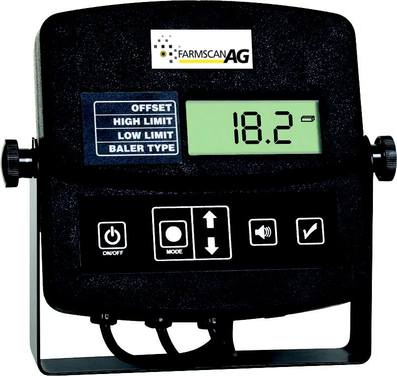
5.0 DEFINITION
“NORMAL OPERATION MODE” ‐ This is the default mode the tester is in at
power up and will be displaying the moisture of the hay in the chamber.
BUTTON FUNCTIONS
POWER ON/OFF (A)
The power on/off button (A) turns the tester on or off.
TURNING THE UNIT ON OR OFF
Press and hold the power on/off button (A) for approximately one second to
turn the unit on. Press and hold the power on/off button (A) for
approximately one second to turn the unit off.
NOTE: Unless you have the tester’s positive (+) 12 volt wire connected to a
power wire that is controlled by the tractor’s ignition switch, the display
module will remain on even after the tractor is turned off. You must turn the
tester off to prevent accidental battery discharge.
Part No:AM-2178
November 201113
WHAT THE CODE DISPLAYED ON THE SCREEN AT POWER UP
MEANS :
When you turn the tester on an Alfa‐numeric code will be displayed. This code
represents the “SOFTWARE VERSION” of the program that your 2178 is using.
If a new program is available it can be updated using the included USB cable
and access to the Internet.
Please check our website for further information on updating your 2178.
MODE (B)
The mode button (B) allows you to select the various mode options
which are:
MOISTURE OFFSET ‐ Used to apply offset to reading
MOISTURE HIGH LIMIT ‐ Used to set high limit
MOISTURE LOW LIMIT ‐ Used to set low limit
BALER TYPE ‐ Small square baler and round baler
USING THE MODE BUTTON :
1. When the mode button (B) is pressed, which can be done at any time, a
blinking triangular indicator (F) will appear next to the mode that is
currently selected. Each time the mode button (B) is pressed the
triangular indicator (F) will toggle to the next mode.
2. Once you have selected the mode option you wish to change, as
indicated by the blinking triangular indicator arrow (F), simply press the
up or down arrows (C) to make the selected mode adjustment.
NOTE: Once you have finished, simply wait approximately 10 seconds,
without touching any buttons. The unit will save your changes and
return to its “NORMAL OPERATING MODE”, and display bale
moisture.
Part No:AM-2178
November 201114
SOUND (D)
The sound button (D) allows you to turn the buzzer sound on or off.
USING THE SOUND BUTTON:
By default, the buzzer sound will be on each time your tester unit is turned on.
If you wish to turn the buzzer sound off, press the sound but‐ ton (D) once.
Press the sound button (D) again to turn the sound back on. If the buzzer is
shut off, an icon of a speaker with a line through it (H) will be displayed in the
lower right corner of the display.
CALIBRATION CHECK (E)
The calibration button (E) allows you to check the calibration of the moisture
tester.
USING THE CALIBRATION CHECK BUTTON:
With the baler chamber empty press the calibration check button (E). The unit
will then count down on the display 5,4,3,2,1. Then, either “CAL” or “Err” will
be displayed. If “CAL” is displayed, it means the unit is calibrated and working
correctly. If “Err” is displayed, it means there was a problem in calibrating the
unit. If you receive the “Err” message please refer to the trouble shooting
section of the manual.
NOTE: After the calibration message is displayed, the unit will return to its
“NORMAL OPERATION MODE”.
Part No:AM-2178
November 201115
6.0 OPERATION OF THE SENSOR
While the bale is being formed in the bale chamber, the 2178 reads and
averages several tests and displays these results every two seconds. Typically,
moisture readings will vary several percentage points in a single bale.
Windrows are not the same moisture from top to bottom. Usually,they will be
wetter at the bottom than in the center due to ground moisture. Windrows
can be wetter on the top due to dew or drier on the top because of sun and
wind. Typically, low moisture hay varies less than high moisture hay.
Continuous readings from the 2178 and other manufacturer’s meters may be
higher than readings from hand‐held hay probe type testers. The 2178 may
read a couple of percentage points higher on average than hay probe type
testers.
The difference in moisture readings is due to differing densities. Some balers
pack the hay more tightly than others do. When a bale is released from the
chamber it relaxes and is less dense then when it was initially being formed in
the chamber. Tightly packed and dense hay bales appear to be higher in
moisture than less tightly and less dense hay bales.
Do not be concerned that these differences exist. Rather, develop a feel for
the acceptable range of moisture for baling based upon your testers readings.
Hay moisture can vary considerably from one part of a field to another. If the
moisture range displayed by the tester increases above or decreases below
your set limits the alarm will sound (unless you have the sound muted or
limits are not set). Stop baling and determine the reason for the change in hay
moisture. You may want to discontinue bailing in this area of the field.
NOTE: Hay with a moisture percentage above 20% should not be baled or
stored without the use of a preservative. Hay with a moisture percentage
above 25% should not be baled or stored.
These recommendations have been made to prevent excessive heating of
the bale and/or mold growth in the hay, and are recommendations of many
agricultural specialists of the agricultural extension offices.
Part No:AM-2178
November 201116
BASIC OPERATION
1. Turn the tester on by pressing the power on/off button (A).
2. The unit will first display the unit’s “software version”.
3. The unit will then display the current baler type selected and also
indicate if there are any offsets or limits set in the tester.
4. You are now ready to bale hay! The tester will now begin to display the
current moisture of the hay in the chamber every 2 seconds.
***If the chamber is empty or the moisture is below the limits of the tester
during the “NORMAL OPERATION MODE” the tester will display “LO” for the
moisture.
***If the moisture is above the limits of the tester during the “NOR‐ MAL
OPERATION MODE” the tester will display “HI” for the moisture.
CHANGE TESTER SETTINGS
SETTING THE BACKLIGHT BRIGHTNESS
The tester’s backlight brightness is set to maximum intensity by default on
power up. When the tester is in “NORMAL OPERATION MODE”, you can adjust
the backlight brightness by pressing the up and down arrow buttons (C). The
down arrow will decrease the brightness and the up arrow will increase the
brightness.
SETTING THE MOISTURE OFFSET
If you determine that the hay is higher or lower than the displayed reading
you can apply an offset to modify the displayed reading. By default the offset
is set to 0%. The offset can be set within a range of ‐10 to +10% in 0.5%
increments.
1. Press the mode button (B) until the triangular indicator (F) is blinking
next to “OFFSET”.
2. Use the arrow buttons (C) to adjust the offset up or down. The offset
you select will be added to or subtracted from the factory calibrated
reading.
NOTE: If there is no offset applied or you wish to turn off the offset
simply set the offset to 0.
Once you have made your changes, they will be saved and will be used
every time the tester is turned on.
Part No:AM-2178
November 201117
If you are done making changes to the offset, without pressing any
buttons, wait approximately 10 seconds and the tester will return to
“NORMAL OPERATION MODE”. If you want to make changes to another
mode you can press the mode button again to change to the next
mode of operation.
3. Once you have made your changes to the offset and if you have a offset
applied, when the tester returns to “NORMAL OPERATION MODE” the
triangular indicator (F) will be solid and pointing to “OFF‐ SET”. This
indicates that you have an offset applied in the tester.
SETTING THE HIGH LIMIT
By default the high limit is turned off. The high limit can be set within a range
of 9 to 30% in 1% increments.
1. Press the mode button (B) until the triangular indicator (F) is blinking
next to “HIGH LIMIT”.
2. Use the arrow buttons (C) to adjust the high limit up or down.
NOTE: If there is no high limit applied, or you wish to turn the high
limit off, simply use the arrow buttons (C) until the word “OFF” is
displayed for the high limit.
3. Once you have made your changes they will be saved and will be used
every time the tester is turned on.
4. If you are done making changes to the high limit, without pressing any
buttons, wait approximately 10 seconds and the tester will return to
“NORMAL OPERATION MODE”. If you want to make changes to another
mode you can press the mode button to change to the next mode of
operation.
5. Once you have made your changes to the high limit, and if you have a
high limit applied, when the tester returns to “NORMAL OPERATION
MODE” the triangular indicator (F) will be solid and pointing to the
“HIGH LIMIT”. This indicates that you have a high limit applied to the
tester.
NOTE: The tester will beep if you have a high limit set and the hay
moisture is above the set limit.
Part No:AM-2178
November 201118
SETTING THE LOW LIMIT
By default the low limit is turned off. The low limit can be set within a range of
9 to 30% in 1% increments.
1. Press the mode button (B) until the triangular indicator (F) is blinking
next to “LOW LIMIT”.
2. Use the arrow buttons (C) to adjust the low limit up or down.
NOTE: If there is no low limit applied, or you wish to turn the low limit
off, simply use the arrow buttons (B) until the word “OFF” is displayed
for the low limit.
3. Once you have made your changes they will be saved and will be used
every time the tester is turned on.
4. If you are done making changes to the low limit, without pressing any
buttons, wait approximately 10 seconds and the tester will return to
“NORMAL OPERATION MODE”. If you want to make changes to another
mode you can press the mode button to change to the next mode of
operation.
5. Once you have made your changes to the low limit, and you have a low
limit applied, when the tester returns to “NORMAL OPERATION MODE”
the triangular indicator (F) will be solid and pointing to the “LOW
LIMIT”. This indicates that you have a low limit applied to the tester.
NOTE: The tester will beep if you have a low limit set and the hay
moisture is below the set limit.
SETTING THE BALER TYPE
1. Press the mode button (B) until the triangular indicator (F) is blinking
next to “BALER TYPE”.
2. Use the arrow buttons (C) to select the required baler type as
indicated by icon (G).
Part No:AM-2178
November 201119
7.0 TROUBLESHOOTING
PROBLEM: Tester will not power on.
SOLUTION:
. Check all power connections and the 2amp fuse inside the fuse holder.
. Use a test light to ensure that the power cable has power.
PROBLEM: Tester will not calibrate and displays “Err” during calibration.
SOLUTION:
. Check all cable and sensor connections to ensure nothing is shorted
. Make sure the chamber is empty before performing the calibration.
. With a light steel wool pad, polish both sensor pads and retry calibration.
PROBLEM: Tester only displays “HI” for the moisture reading.
SOLUTION:
. Check all cable and sensor connections to ensure nothing is shorted.
. Determine by some other means if the hay being tested is with the operating
limits of the tester.
PROBLEM: Tester only displays “LO” for the moisture reading.
SOLUTION:
. Check all cable and sensor connections to ensure nothing is open.
. Determine by some other means if the hay being tested is with the operating
limits of the tester.
PROBLEM: Tester reading seems to read erratic or incorrect.
SOLUTION:
. See the section of the manual “UNDERSTANDING HAY CONDITIONS AND
TEST READINGS”. If all of these steps fail, please read the manual again
Part No:AM-2178
November 201120
carefully
8.0 SERVICE
REPLACING A SENSOR PAD
The sensor pads and contacts can become worn. Contact your Farmscan AG
dealer to order replacement sensor pads. See “INSTALL MOISTURE SENSORS”
for installation instructions.
CARE, MAINTENANCE AND STORAGE
After each use or after the harvest season, remove the display module (if it is
not inside a dry cab) and store in a clean and dry place.
Always use the weatherproof plug covers on the sensor cables to keep
moisture and dirt from getting into the electrical contacts.
The stainless steel contacts on the moisture sensors should be kept clean for
the best results. Clean with fine steel wool and/or mineral spirits or alcohol.
Dirty contacts can cause lower readings.
Check all nuts and screws on the moisture sensor plates and tighten if
necessary. Make sure the sensor pad leading edge is secured flat and tight to
the bale chamber wall.
TESTER ACCESSORIES
Replacement Sensor Pads (Farmscan AG part number: 2178S ), all nuts, screws
and spacers used for replacing a worn sensor pad.
We recommend changing both sensor pads at the same time.
Part No:AM-2178
November 2011You can also read