DCH full simulation and full IDEA description integration - G.F. Tassielli, F. Cuna, N. De Filippis, W. Elmetenawee, L. Lavezzi
←
→
Page content transcription
If your browser does not render page correctly, please read the page content below
DCH full simulation
 and
 full IDEA description integration

 G.F. Tassielli,
 F. Cuna, N. De Filippis, W. Elmetenawee, L. Lavezzi

02/17/2021 RD_FCC collaboration meeting 1/20
Outline Drift Chamber simulation Review geometry and reconstruction status Cluster Counting/Timing simulation Integration with the Calorimeter Summary and Plans 02/17/2021 RD_FCC collaboration meeting 2/20
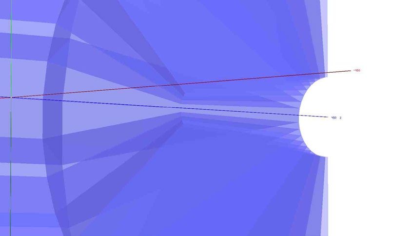
Drift Chamber simulation - Review geometry and reconstruction status A full geant4 simulation of the IDEA tracking system was developed to test the tracking performance The DCH is simulated at a good level of geometry details, including detailed description of the endcaps; SVX and Si wrapper and PSHW are simulated as simple layer or overall equivalent material; KF with simple track selection criteria was used: only a quality cut on Chi2/nDof < 25 was applied; A preliminary SVX and DCH description inside the FCC-sw was implemented More details in: G. Tassielli: "Tracking performance with the updated geometry of the IDEA detector ", 11th FCC-ee workshop, CERN, January 2019" N. A. Tehrani: “Simulation and tracking studies for a drift chamber at the FCC-ee experiment”, CERN-ACC-2019-0043 02/17/2021 RD_FCC collaboration meeting 3/20
Drift Chamber simulation - Review geometry and reconstruction status
 assumed: σd = 100 µm and (conservative for Si) σSi = pitch/√12 µm
σpt/pt

 >100 Hits per tracks |ϑ| 60 Hits per tracks |ϑ| 99.5%
 in the PR algorithm
 (defined as reconstructed track
 with >60% good hits)

 02/17/2021 RD_FCC collaboration meeting 4/20
Drift Chamber simulation - Review geometry and reconstruction status
Transparency more relevant than asymptotic resolution, the particle range is far from the
asymptotic limit where MS is negligible.

 σ p (100GeV )
 t
 = 4 • 10 −5
 pt2

CLD: a detector concept for FCC-ee with a full Si-tracker system, inspired by CLIC detector.

 02/17/2021 RD_FCC collaboration meeting 5/20
Drift Chamber simulation - Review geometry and reconstruction status
Preliminary study of the machine background induced occupancy on the DCH,
indicate that, it will be not an issue

 02/17/2021 RD_FCC collaboration meeting 6/20
Drift Chamber simulation - Cluster Counting/Timing simulation To investigate the potential of the Cluster Counting technique (for He based drift chamber) on physics events a reasonable simulation/parameterization of the ionization clusters generation in Geant4 is needed. Garfield/Garfield++: (Heed) simulates the ionization process in the gasses (not only) in a detailed way. (Magboltz) computes the gas properties (drift and diffusion coefficients as function of the fields value) solves the electrostatic planar configuration and simulates the free charges movements and collections on the electrodes. So Garfield can study and characterize the properties and performance of single cell or drift chamber with simple geometry, but is not designed to simulate a full detector neither study collider events. Geant4: Simulates the elementary particle interaction with material of a full detector Studies colliders events It doesn’t simulate (normally) the ionization clustering process It doesn’t simulate (normally) the free charges movements and collections on the electrodes. It is very useful to simulate a the elementary particle interaction with the material of a full (complex) detector and to study collider events. The fundamental properties and performance of the sensible elements (drift cells) have to be parametrized or ad-hoc physics models have to be defined. 02/17/2021 RD_FCC collaboration meeting 7/20
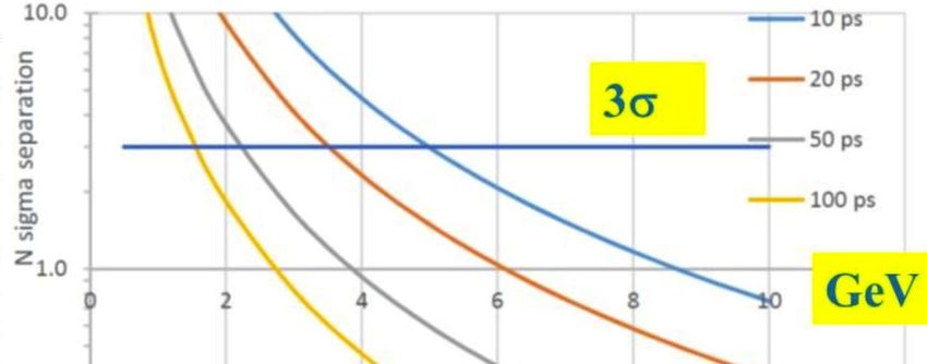
Drift Chamber simulation - Cluster Counting/Timing simulation

 Garfield++ Geant4

 Truncated
 mean at 70%

 We are simulating 2m long tracks which pass through a 1 cm long
 side box of 90% He and 10% iC4H10 , with Garfield++ and Geant4
 Garfield++
 ∆ − ∆
 = is the average of the two resolutions.
 ,
 Cluster counting leads to an improvement on particle
 separation power.
 As example, around 5 GeV the power separation of a pion from
 kaon obtained with traditional method is about 4, the one
 obtained with cluster counting is around 8.

 02/17/2021 RD_FCC collaboration meeting 8/20
Drift Chamber simulation - Cluster Counting/Timing simulation
Studying the results from Garfield++ simulations, we can interpret correctly the results obtained from Geant4
simulations with the goal of reconstruct the number of clusters and the cluster size generated from different particles
with different momenta passing through the tracker detector.
The goal is to extract from Garfield++ the relevant parameters to create models to convert the energy loss to
cluster and then extract them as function of the primary particle βγ.

 Number of cluster from Garfield++

 Here the distribution of number of cluster produced by different
 particle at different momenta, obtained with Garfield++

 02/17/2021 RD_FCC collaboration meeting 9/20
Drift Chamber simulation - Cluster Counting/Timing simulation

 Kinetic energy distribution for cluster with cluster size
 equal to 1. The fit is the sum of an exponential function
 plus a Gaussian function.

Kinetic energy distribution for cluster with cluster size higher than 1 (left) and up to 1keV cut (right).
The fits are performed with a Landau functions.

 1keV cut is
 equivalent to the
 single interaction
 range cut set (by
 default) in Geant4

 02/17/2021 RD_FCC collaboration meeting 10/20
Drift Chamber simulation - Cluster Counting/Timing simulation

 maxExEcl=(Etot-maxEx0+gRandom→Gaus(0,ExSgm))/maxExSlp
 MaxEx0 is the first parameter of the linear fit
 MaxExSlp is the second parameter of linear fit
 ExSgm is the average of the sigma of each point in the correlation trend.

 − 0 + → 0,
 =

 The figure shows an example of distribution of total energy loss for extra
 energy between 90 and 100 eV for cluster with cluster size higher than one.

 02/17/2021 RD_FCC collaboration meeting 11/20
Drift Chamber simulation - Cluster Counting/Timing simulation

We implemented seven different algorithms trying to reproduce the number of cluster and the cluster size.
The first step common to all algorithm is the evaluation of the total kinetic energy for cluster with cluster size higher than
one (maxExEcl) event by event.

1) The first algorithm uses a reference value of the ratio between clusters containing a single electron and clusters
containing more than one electron (Rt). Using the Rt value, the algorithm chooses to create cluster with cluster size one or
higher. Then, it assigns the kinetic energy to each cluster by using the proper distributions. If the cluster has more than one
electron, a check on the total kinetic energy is performed and its cluster size is evaluated. The procedure is repeated until
the sum of primary ionization energy and kinetic energy per cluster saturate the energy loss of the event.

2) The second algorithm, if maxExEcl is higher than zero, generates the kinetic energy for clusters with cluster
size higher than one by using its distribution and evaluates cluster size. This procedure is repeated until the sum
of primary ionization energy and kinetic energy per cluster saturate the maxExEcl of the event.
Then, using the remaining energy (Eloss-maxExEcl), the algorithm creates clusters with cluster size equal to
one by assigning their kinetic energy according to the proper distribution.
The reconstruction of clusters with cluster size equal to one remains the same for all next algorithms.

3) The third algorithm (similar to the previous), during the generation of cluster with cluster size higher than
one, assigns the kinetic energy to them, choosing the best over five extractions that makes the total kinetic
energy for cluster with cluster size higher than one approximating better the maxExEcl.
To correct a systematic underestimation of the mean number of clusters, an additional correction to the residual
energy for generating cluster with cluster size equal to one can be used.

 02/17/2021 RD_FCC collaboration meeting 12/20
Drift Chamber simulation - Cluster Counting/Timing simulation

4)The fourth algorithm (similar to the previous), during the generation of cluster with cluster size higher than one,
assigns (by extracting from the proper distribution) the kinetic energy to them, until the total kinetic energy better
approximates the maxExEcl.

5)The fifth algorithm is similar to the fourth with almost differences in the technical implementation.

6)The sixth algorithm follows a different methodology. Indeed it uses the total kinetic energy of the event
to evaluate a priori the number of cluster, applying the most likelihood criterium.

7)The last algorithm is similar to the second algorithm but generates the kinetic energy for cluster with cluster size
higher than one by using the fit of kinetic energy distribution.

List of variables
maxExEcl : total kinetic energy spent to create clusters with cluster size higher than 1
ExECl : kinetic energy generated per cluster
Ncl1 : number of clusters with cluster size equal to one
Nclp : number of clusters with cluster size higher than one
maxCut : energy value equivalent to the range cut set in Geant4
totExECl : total kinetic energy reconstructed to create clusters with cluster size higher than one
Eloss : energy loss from a track passing through the cell
ClSz : cluster size
Eizp : primary ionization energy, 15.8 eV
Eizs : secondary ionization energy, 25.6 eV

 02/17/2021 RD_FCC collaboration meeting 13/20
Drift Chamber simulation - Cluster Counting/Timing simulation
 Case of study: muon at 300 MeV

MC Truth

1st algorithm

 02/17/2021 RD_FCC collaboration meeting 14/20
Drift Chamber simulation - Cluster Counting/Timing simulation
 Case of study: muon at 300 MeV

3th algorithm

6th algorithm

 02/17/2021 RD_FCC collaboration meeting 15/20
Drift Chamber simulation - Cluster Counting/Timing simulation

 Ncl σNcl Ncl1 σNcl1 Nclp σNclp maxNclp eff. Nclp ClSz σClSz

 MC. T. 11.96 3.458 10.44 3.228 1.912 1.04 10.05 1.705 6.498
 1 14.69 6.959 12.85 6.426 2.157 1.25 13.5 1.082 1.424 5.569
 2 11.53 3.612 9.225 3.633 3.448 2.602 25.5 0.899 1.775 6.483
 3 (no corr.) 10.99 3.72 9.339 3.608 2.428 1.321 14.5 0.886 1.828 6.695
 3 (+ corr.) 11.94 3.758 10.25 3.69 2.429 1.317 12.5 0.889 1.762 6.367
 4 11.63 3.642 9.388 3.633 3.349 2.675 24.5 0.889 1.753 6.434
 5 12.11 3.808 9.533 3.935 4.186 2.972 24.5 0.820 1.698 6.231
 6 11.36 3.525 9.501 3.511 2.724 1.311 12.5 0.886 1.787 6.67
 7 7.012 4.026 7.593 3.862 2.286 1.258 12.5 1.295 2.485 9.012

The second and third algorithms produce a number of cluster distribution, which follows the Poissonian shape and
gives a mean value compatible with the one expected.
The sixth algorithm produces a number of cluster distribution, which follows the Poissonian shape and gives a mean
value compatible with the one expected and also reconstructs a cluster size distribution whose shape is similar to the
one expected.
The other algorithms do not well reproduce the Poissonian shape expected for number of clusters distribution.

 02/17/2021 RD_FCC collaboration meeting 16/20
Drift Chamber simulation - Cluster Counting/Timing simulation
 Case of study: muon at 300 MeV

 Geant4 result
 The algorithm is tested with Geant4 simulations and the results obtained are compatible with the ones
 obtained with Garfield++.

 Garfield++ Geant4

 02/17/2021 RD_FCC collaboration meeting 17/20
Drift Chamber simulation - Cluster Counting/Timing simulation
 Case of study: pion at 10 GeV

MC Truth

6th algorithm

 02/17/2021 RD_FCC collaboration meeting 18/20
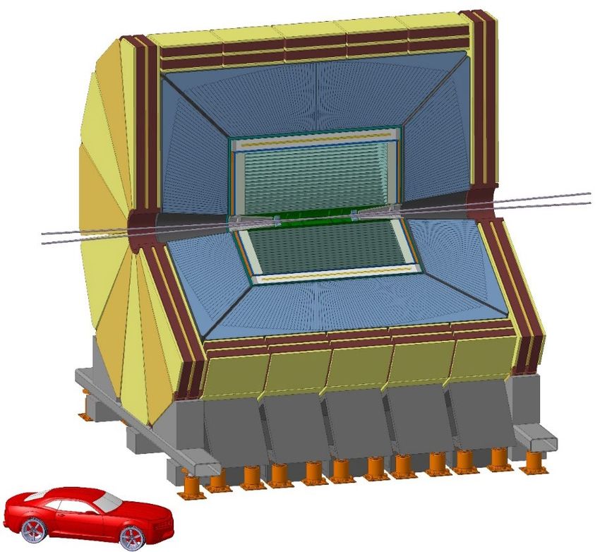
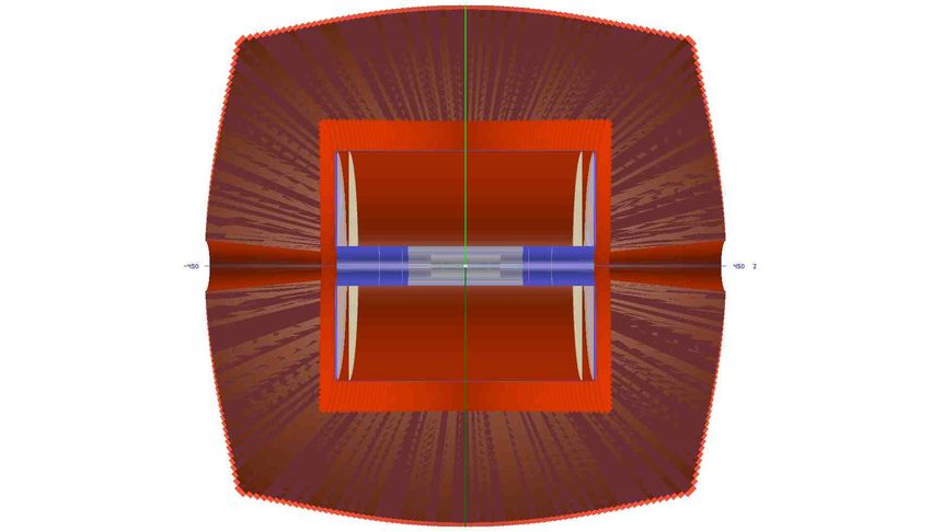
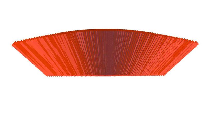
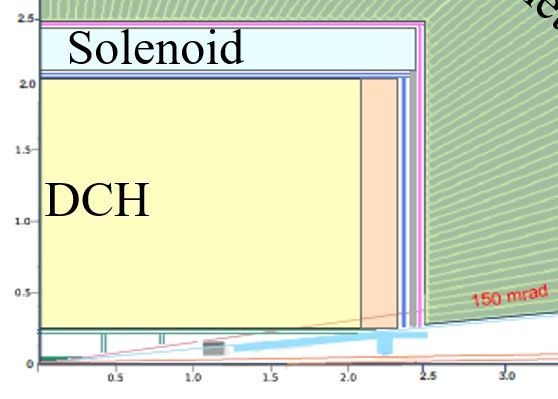
Integration with the Calorimeter
 The integration of the Calorimeter geometry description was performed

 Phi volume (barrel)

 Phi volume (Endcap)

 02/17/2021 RD_FCC collaboration meeting 19/20
Summary A Geant4 simulation of the Drift Chamber and tracking system is set and working. Reasonable algorithms to simulate the Ionization Clusters by using the Geant4 data are developed The DR calorimeter geometry description is integrated with the other detectors. https://github.com/welmeten/DriftChamberPLUSVertex/tree/master To do and Plans Import the DR calorimeter step/hit creation (Walaa is working) Update the code to use the key4hep stack environment to run and migration form Make to Cmake (Lia is working) Convert the data output to EDM4hep formats (Lia is working) Finalize the Cluster simulation algorithms (Federica is working)and implement it in the DCH hit creation (To be assigned) Integrate the “correct” preshower description (geometry and hit creation) (To be assigned) Studies on C.C., improvements on track reconstruction, P.R. …. improve Clustering algorithm validation improve synergies with BINP colleges To speed up the processes more people are needed!!! 02/17/2021 RD_FCC collaboration meeting 20/20
Backup

02/17/2021 RD_FCC collaboration meeting 21/20
Expected performance
Machine background will be not an issue
• average machine background occupancy of the DCH is ~ 0.3% (3%) per bunch
 crossing at 91:2 (365) GeV, in the innermost layers.
• The maximum drift time (400ns) will impose an overlap of some (20 at Z pole)
 bunch crossings bringing the hit occupancy to ~ 10% in the inner-most drift cells.
 Based on MEG-II experience, this occupancy, which allows over 100 hits to be
 recorded per track on average in the DCH, is deemed manageable.
• However, signals from photons can therefore be effectively suppressed at the data
 acquisition level by requiring that at least three ionization clusters appear within a
 time window of 50 ns.
• In addition, cluster signals separated by more than 100 ns are not from the same
 signals, this effectively bring the BXs pile-up from 20 to 4

 02/17/2021 RD_FCC collaboration meeting 22/20
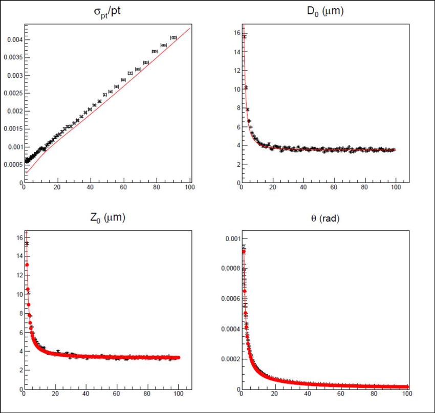
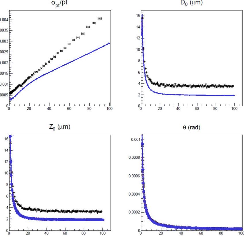
Expected simulated performance
 Analytic model to evaluate full
 covariance matrix

 black point: Full simulation
 red line: analytic model with Si resolution
 as Full sim.
 blue line: analytic model with improved Si
 resolutions*

 p [Gev/c] p [Gev/c] * Vertex:
 90o • inner 3x3 µm
 • outer/forward 7x7 µm
 Si wrapper: 7x90 µm

 4·10-5
 σ p (100GeV )
 t
 :
 pt2

 p [Gev/c] p [Gev/c]
 2.9·10-5

 More details in F. Bedeschi: "Fast Simulation Tracking",
 Workshop on the Circular Electron-Positron Collider, Oxford, UK, April 2019"

 02/17/2021 RD_FCC collaboration meeting 23/20
Cluster Counting/Timing and P.Id. expected performance Expected excellent K/π separation dN/dx over the entire range except e/μ μ/π 0.85
The MEG-II Drift Chamber Performance

spatial resolution on 7 mm cell hits in 250 ns window

 3D
 both views

 σ = 106 μm track finding
 and fit
 (He/iC4H10 = 85/15)
 arXiv:1605.07970

 segment fit + turn merging

 zoom
 discard short segments and isolated hits
 full track fit signal
 track

 michel
 tracks

 02/17/2021 RD_FCC collaboration meeting 25/20
The IDEA drift chamber tracking efficiency ε ≈ 1 0.016 X0 to barrel calorimeter for ϑ > 14° (260 mrad) 0.050 X0 to end-cap calorimeter He based gas mixture 97% solid angle (90% He – 10% i-C4H10) service area Full stereo configuration 0.20 m (F.E.E. included) with alternating sign stereo 0.016 X0 active area 0.045 X0 angles ranging from 50 to r = 2.00 m 250 mrad 0.050 X0 112 layers 12÷14.5 mm wide square ϑ=14° cells 5 : 1 field to sense Front Plate 12-15 mm cell width r = 0.35 m wires ratio inner wall 0.0008 X0 z-axis 56,448 cells 56,000 cells 14 co-axial super-layers, 8 340,000 wires layers each (112 total) in 24 (0.0013+0.0007 X0/m) equal azimuthal (15o) wires gas sectors outer wall 0.012 X0 (Ni = 192 + (i − 1) × 48) z = 2.00 m 02/17/2021 RD_FCC collaboration meeting 26/20
Novel approach at construction technique of high granularity and high transparency Drift Chambers wire cage Based on the MEG-II DCH new construction technique the IDEA DCH can meet these goals: Gas containment – wire support functions separation: allows to reduce material to ≈ 10-3 X0 for the inner cylinder and to a few x 10-2 X0 for the end-plates, including FEE, HV supply and signal cables gas vessel Feed-through-less wiring: allows to increase chamber granularity and field/sense wire ratio to reduce multiple scattering and total tension on end plates due to wires by using thinner wires Cluster timing: allows to reach spatial resolution < 100 μm for 8 mm drift cells in He based gas mixtures (such a technique is going to be implemented in the MEG-II drift chamber under commissioning) Cluster counting: allows to reach dNcl/dx resolution < 3% for particle identification (a factor 2 better than dE/dx as measured in a beam test) 02/17/2021 RD_FCC collaboration meeting 27/20
Cluster Counting/Timing and P.Id. expected performance
 acquired identified
From the ordered sequence of the electrons signal peaks
arrival times, considering the average time
separation between clusters and their time
spread due to diffusion, reconstruct the most
probable sequence of clusters drift times:

 dE/dx dNcl/dx

 from Walenta parameterization (1980) from Poisson distribution

truncated mean cut (70-80%) reduces the amount of δcl = 12.5/cm for He/iC4H10=90/10 and a 2m
collected information n = 112 and a 2m track at 1 track give
atm give σ ≈ 2.0%
 σ ≈ 4.3% A small increment of iC4H10 from 10% to 20%
Increasing P to 2 atm improves resolution by 20% (σ (δcl = 20/cm) improves resolution by 20% (σ
≈3.4%) but at a considerable cost of multiple ≈1.6%) at only a reasonable cost of multiple
scattering contribution to momentum and angular scattering contribution to momentum and
resolutions. angular resolutions.
 Moreover, C.C. allows can improve the spatial resolution < 100 μm for 8 mm drift cells in He based gas mixtures

 02/17/2021 RD_FCC collaboration meeting 28/20
IDEA DCH geometry (simulation)
Electronics boards: 12 cm x 6 cm x 3mm G10 (FR4);

signal cables:
 2.032 cm x 25 µm Kapton
 + 40 µm 16 pairs of Copper wires;

HV cables:
 500 µm Copper wire
 + 500 µm Teflon insulation;

Wire anchoring (see next slide);

Carbon fiber wire support.

 Connecting ring is described as a circular layer:
 0.5 cm x 1.5 cm Carbon fiber

 02/17/2021 RD_FCC collaboration meeting 29/20
IDEA DCH geometry (simulation) FWboard The wire anchoring system: Field wire board: 4 mm x 200 µm G10(FR4); Spacer: made of polycarbonate, Spacer instead of holes it is drawn with spokes but with SWboard the same area ratio. Sense wire board: 1 cm x 200 µm G10(FR4) plus Spacer components: 1) termination resistance: 1.6 mm x 800 µm x 450 µm Aluminum; FWboard 2) HV Capacitance: 3.17 mm x 1.57 mm x 1.7 mm Aluminum; 3) HV resistance (only downstream): 5 mm x 2.5 mm x 550 µm Aluminum. 02/17/2021 RD_FCC collaboration meeting 30/20
IDEA tacking system – ly1 - SVX

 Layer R L Si eq. thick. X0 pixel size area # of
 [mm] [mm] [μm] [%] [mm2] [cm2] channels
 1 17 ±110 300 0.3 0.02×0.02 235 60M
 2 23 ±150 300 0.3 0.02×0.02 434 110M
 3 31 ±200 300 0.3 0.02×0.02 780 200M
 4 320 ±2110 450 0.5 0.05×1.0 85K 170M
 5 340 ±2245 450 0.5 0.05×1.0 96K 190M

 Disks Rin Rout z Si eq. X0 pixel size area # of
 [mm] [mm] [mm] thick. [%] [mm2] [cm2] channels
 [μm]

 1 62 300 ±400 300 0.3 0.05×0.05 5.4K 220M

 2 65 300 ±420 300 0.3 0.05×0.05 5.4K 220M

 3 138 300 ±900 300 0.3 0.05×0.05 4.4K 180M

 4 141 300 ±920 300 0.3 0.05×0.05 4.4K 180M

 02/17/2021 RD_FCC collaboration meeting 31/20
IDEA tacking system – ly1 - DCH

 Rin Rout z
 [mm] [mm] [mm] active volume 50 m3
 drift chamber 350 2000 ±2000
 readout r.o. from both
 112,896
 service area 350 2000 ±(2000÷2250) channels ends

 800 × 8 bit at 2
 inner outer service max drift time 400 ns
 gas wires GHz
 wall wall area
thickness [mm] 0.2 1000 1000 20 250
 X0 [%] 0.08 0.07 0.13 1.2 4.5

 # of layers 112 min 11.8 mm – max 14.9 mm

 # of cells 56448 192 at 1st – 816 at last layer

 average cell size 13.9 mm min 11.8 mm – max 14.9 mm

 average stereo angle 134 mrad min 43 mrad – max 223 mrad

 transverse resolution 100 μm 80 μm with cluster timing

 longitudinal resolution 750 μm 600 μm with cluster timing

 02/17/2021 RD_FCC collaboration meeting 32/20
IDEA tacking system – tentative layout

 Base Line Option 1 Option 2

 value value value dim.
 Rin 345 200* 250 mm
 Rout 2000 2150 2000 mm * not over the entire length,
 active area length 4000 4000 4000 mm to avoid overlap with
 beam pipe etc.
 total length 4500 4500 4500 mm A possible construction
Geometry is not
yet optimized: total cells 56448 34560 52704 n. strategy is available.
 layers 112 96 112 n.
 Superlayers 14 12 14 n.
 Layers per Superlay. 8 8 8 n.
 phi sector 12 12 12 n.
 smaller cell 11.85 14.2 11.65 mm
 larger cell 14.7 22.5 15.25 mm
 min. stereo angle 48 25 35 mrad
 max. stereo angle 250 240 245 mrad

 02/17/2021 RD_FCC collaboration meeting 33/20
IDEA – layout v1 – Expected tracking performance
 BARREL: FORWARD:

 χ2 /ndof

 > 100 Hits at 10 deg
N hits fitted per track no hits in DCH
(DCH)

 02/17/2021 RD_FCC collaboration meeting 34/20
IDEA – layout v1 – Expected tracking performance
 BARREL: FORWARD:

 p

 pt
σpt
 = 4 • 10 −5
pt2

σpt
 = 5 • 10 −5
pt2

 02/17/2021 RD_FCC collaboration meeting 35/20
IDEA – layout v1 – Expected tracking performance
 BARREL: FORWARD:

impact parameter

 Z

 02/17/2021 RD_FCC collaboration meeting 36/20
IDEA – layout v1 – Expected tracking performance
 BARREL: FORWARD:

theta

phi

 02/17/2021 RD_FCC collaboration meeting 37/20
IDEA tracking system – Expected tracking performance
 (single muon as function of ϑ)

base line option p pt

momentum
resolution:

 phi theta

angular vertex
resolution:

 02/17/2021 RD_FCC collaboration meeting 38/20
IDEA tracking system – Expected tracking performance
(single pi+ at fixed θ=65deg)
 Note: DCH layout differs a bit from the final IDEA one,
 only to compare the relative effects

 02/17/2021 RD_FCC collaboration meeting 39/20
The IDEA tracking system
 Solenoid: 2 T, length = 5 m,
 r = 2.1-2.4 m, 0.74 X0, 0.16 λ @ 90º

 Si Wrapper:
 2 layers of µ-strips (50 µm x 1 mm)
 both barrel and forward regions

 DCH: 56448 (~1.2 cm) cells
 He based gas mixture
 (90% He – 10% i-C4H10)

 % X0
 Luminometer ~ 5% X0 - barrel
 < 15% X0 - forward
 Vertex:
inner: 3 single Si pixel (20 µm x 20 µm) layers of 0.3% X0
outer: 2 single Si pixel (50 µm x 50 µm) layers of 0.5% X0
forward : 4 single Si pixel (50 µm x 50 µm) layers of 0.3% X0

 02/17/2021 RD_FCC collaboration meeting 40/20
Cluster Counting/Timing and P.Id. expected performance
In He based gas mixtures the signals from each ionization act can be spread in time to few ns. With the
help of a fast read-out electronics they can be efficiently identify.
Counting the number of ionization acts per unit length (dN/dx) is possible to identify the particles (P.Id.)
with a better resolution than dE/dx method.

 acquired signal identified
 peaks

 dE/dx dNcl/dx
truncated mean cut (70-80%) reduces the amount of δcl = 12.5/cm for He/iC4H10=90/10 and a 2m
collected information. n = 112 and a 2m track at 1 track give
atm give σ ≈ 4.3% σ ≈ 2.0%

 Moreover, C.C. may improve the spatial resolution < 100 μm for 8 mm drift cells in He based gas mixtures

 02/17/2021 RD_FCC collaboration meeting 41/20
You can also read