THORIUM UTILIZATION FOR SUSTAINABLE SUPPLY UC S. BANERJEE - OF NUCLEAR ENERGY DEPARTMENT OF ATOMIC ENERGY INDIA CIRUS
←
→
Page content transcription
If your browser does not render page correctly, please read the page content below

THORIUM UTILIZATION FOR SUSTAINABLE SUPPLY
            OF NUCLEAR
            O   UC      ENERGY
                            G
                S. BANERJEE
        DEPARTMENT OF ATOMIC ENERGY
                   INDIA

              DHRUVA             CIRUS

                                             1
PLAN OF
                    O TALK

Introduction

Th
Three Stage
      St    Nuclear
            N l     Power
                    P     Programme
                          P

Thorium Utilisation for sustainable
Nuclear Energy

Related ongoing activities and plans

Summary
For Long Term Energy Security and Large
Scale Utilization of Thorium Reserves in
the country,
    country India has a robust Three Stage
Power Programme in place.

Development of Thorium Based Reactor
Systems for sustainable Nuclear Energy
belongs to the third stage
Indian nuclear energy policy
• Commitment to high economic growth rate by
  a populous country.
• Indigenous and largely home-grown nuclear
  power program.
• Limited resources of uranium- to be
  judiciously utilized.
• Vast and easily accessible thorium reserves-
  to be eventually harnessed.
• Commitment to closed fuel cycle for optimum
  resource utilization.
• Safety
  S f t andd energy security
                          it are vital.
                                  it l
                                           4
THREE STAGE NUCLEAR POWER PROGRAMME

Nat U , HEAVY WATER BASED PHWR - I Stage

Pu FROM THE Ist STAGE USED IN THE
FAST BREEDER REACTOR
              REACTOR, WHERE 232Th IS ALSO
COVERTED TO 233U - II Stage

233U FROM
       O SECOND
            S CO       STAGE
                       S G ISS USED
                                S   IN THE THIRD
STAGE ALONG WITH 232Th ( Pu MAY BE USED IN
ADDITION)) - III Stage
                    g

Reduces the volumes of waste to be handled
With the closed fuel cycle , Nuclear is near renewable
                               courtesy: Dr. R. Chidambaram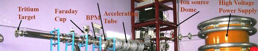
Indian Nuclear Power Programme - 2020
CAPACITY
CUMULATIVE
REACTOR TYPE AND CAPACITIES (MWe) CAPACITY (MWe)
> 19 reactors at 6 sites in operation 4,560 4,560
Tarapur Rawatbhata,
Tarapur, Rawatbhata Kalpakkam,
Kalpakkam
Narora, Kakrapar and Kaiga
1 PHWR under construction at 220 4,780
RAPP-6(220
( MWe))
2 LWRs under construction at 2,000 6,780
Kudankulam(2x1000 MWe)
PFBR under construction at
Kalpakkam (1 X 500 MWe) 500 7,280
> P
Projects
j t planned
l d till 2020 7 900
7,900 15 180
15,180
PHWRs(8x700 MWe), FBRs(4x500 MWe),
AHWR(1x300 MWe)
Additional LWRs through international ~ 20000 ~ 35000
cooperationNuclear fuel resources : India
Uranium: up to 60,000 metric tons
(deposits require elaborate mining operations for extraction)
Natural Uranium contains 0.7% isotope U-235 for
use as fuel (with or without enrichment).
Thorium: ~ 1000,000
~290,000 metric tons
(Available in beach sands -requiring minimum mining operations for
extraction)
Thorium contains no fissile isotope, but it can
breed into U-233 by absorbing a spare neutron
available in a nuclear reactor, which fissions on
subsequent neutron absorption.
8Attributes of Thorium
Significantly more abundant than uranium
Better Performance Characteristics
• Higher melting point
• Better thermal conductivity
• Lower fission gas release
• Good radiation resistance and dimensional stability
Better
B tt ChChemical
i l Stability
St bilit
• Reduced fuel deterioration in the event of failure
• No oxidation during permanent disposal in repository
• Poses problem in dissolution during reprocessingAttributes of thorium Better self sustainability [ σa of 232Th ((7.4 barns)) is three times that of 238U (2.7 barns)] Lower levels long lived minor actinide generation Presence of 232U in 233U [Acts as proliferation resistant but poses problem in fuel fabrication]
Fission neutrons availability in
breeder reactors
• Fuel doubling time
5 eta = Fission
Number neutrons per n
of neutrons depends on: surplus
absorptionper
released in fuel
fission neutrons per
absorption in the
4 233U ((2.28)) reactor fuel.
3 235U(2.04)
239Pu(1.94)
Thermal n (However, all neutron
surpluses to be suitably
absorbed for safe reactor
operation.)
2 • 239Pu-fuel
: has surplus
235
U neutrons only in fast
1 U
233
spectrum.
239
Pu • 233U-fuel: has similar
0 -2 0 2 4 6 8
neutron surpluses in
10 10 10 10 10 10 fast & thermal spectra.
Neutron energy (eV)
11Use of Thoria bundles in PHWR [Also irradiated in pile loops in Research Reactor]
Post Irradiation Examination
Power Peaking in the central elements
Atom % fission = 1
1.25%
25%
Isotopic Composition of Discharged Uranium (%)
232U 233U 234U 235U 236U 238U
Mass
Spectrometric 0.0459 88.78 9.95 1.0 0.085 0.14
Analysis
Theoretical
Prediction * 0.0491 90.556 10.945 1.07 0.0918 -
Fission products measured were
125Sb, 134Cs, 137Cs, 144Ce
Ce-144Pr, 154Eu, 155Eu, 90Sr.
Gross activity of the bundle measured.Radiological
g concerns during
g storage
g
Radioactivity levels much higher for the reprocessed thoria
compared to that of mined thoria due to higher concentration of
228Th ( concentration is in ppm instead of ppb)
A storage period of 16-20 years brings down the radio-activity
levels to that of mined thoria.
Requires suitable ventilation for large releases of thoron.
Thoria can be recycled in the remote fabrication of (Th-233U)
MOX fuel without any storage period after reprocessing232Th and 232U decay
y chainIsotopes in the Th-U fuel cycle Schematic view of the thorium fuel cycle.
NEUTRON DATA of Interest to ADS programme

Need for more and improved quality data(abs, fiss,
fissprod, n mult) for Th – U Cycle Nuclei ( 231-233 Pa,
232 233U)- radioactive target
232,233U)-

Data for Minor Actinides required ( Np, Am, Cm)

Need for data for Pb, Bi , Structural Materials at energies
Higher
  g    than 20 MeV

Prediction and Measurement of Rare Earth Alpha Emitters
Produced in LBE spallation target

Production of Light Radioactive/toxic nuclei like 7Be

Neutron capture data for long lived FF –
129I, 135Cs,107Pd,93Zr
Determination of the 233Pa(n, f) reaction cross-section from
11.5 to 16.5 MeV neutron energy by hybrid surrogate ratio approach

                                                      232Th+6Li

                                                      232Th+4He
                                                      (235U+n)

                                                      232Th+2H
                                                      (233Pa+n)

     B.K.Nayak( Phys Rev. C (2009)rapid
Thorium Utilization Strategies for the Third Stage
Addition of isotopes like U-235
U 235 and Pu
Pu-239
239
In the Thorium feed
Molten Salt Reactor where Fission products
Could be removed through on-line chemistry
Addition of external Neutrons into the Reactor
Environment – such as in ADSGenerating “External Neutrons”
These would be generated by non-fission events.
These could be knocked off from suitable nuclei by
collision of energetic primary particles.
particles
Examples:
Process Example Yield Energy cost-
on target only*
(D,T) fusion 400 KeV on T 4x10⁻⁵ n/D 10,000 MeV/n
Li (D,n)
(D n) break up 35 MeV D on Li 2 5 x 10⁻³ n/D
2.5 14 000 MeV/n
14,000
U-238(,n) 20 MeV e- on U- 1x 10⁻² n/e- 2000 MeV/n
photo-nuclear 238
Spallation 800 MeV proton ~ 30 n/p 27 MeV/n
on U-238
* Plug –point power/energy to particle kinetic energy conversion efficiency will affect
overall (real) energy cost per neutron.
22Basic functions of ADS sub-systems
A
Accelerator
l t coupled
l d to
t Reactor
R t
• Proton accelerator
• intense beam of high energy accelerated
particles (p)
• Spallation
S Target
• high-Z material is target
• neutrons
t emitted
itt d in
i nuclear
l reaction
ti
induced by high-energy protons.
• Sub-critical reactor
• operates through continuation of self-
terminatingg fission chains,, each triggered
gg
by spallation neutron or its derivative
neutron.WHY ADS ?
•Inherently safe
•Sub – critical ---self terminating fission chain
yp
•No restriction on fuel type
•less dependence on delayed neutrons
•Ideally suited for long lived MA incineration
•(Note: Fast Reactor MA/Th > 3% not permitted)
•Better n per fission----Reduced Doubling time
Increased burnup – Less fissile material inventory
F t / Thermal
Fast Th l Reactor
R t combination
bi ti possible
ibl
Large Scale utilisation of Th - complement AHWR
•Large
2Once through Th cycle PHWR ADS
• Initial fuel: Nat
Nat. U & Th
• Normal refuelling of U bundles (say 7
GWd/t)
• Th will reside longer
– U-233 generation adds reactivity
– Compensate by replacing some U
by Th
• Th increases and U decreases
• Ultimately fully Th core
– In situ breeding and burning Th
• Advantages
– Use of natural fuels only
– 140 tons U consumption during
reactor life
– High burnup of Th ~ 100 GWd/t
• Disavantage
– Low keff ~0.9 and gain < 20 with
Pb target
– Accelerator power ~ 30 MW for a 200 MWe ADSPower in ADS is inversely proportional to sub
sub-criticality
criticality
and directly proportional to neutron source strength
In the control rod free concept, the operating keff is limited to the
range 0 0.95-0.98
95-0 98
This requires accelerator beam power of about 10 MW
The one-way coupled booster-reactor concept can reduce this
requirement
q five fold
Inner fast core with source at centre boosts the neutron source
These neutrons leak into the outer thermal (PHWR/AHWR) core
where they undergo further multiplication This cascade
multiplication gives very high energy gain Due to the absorber
lining and the gap very few neutrons return to the booster – i.e.
there is a one way-coupling between the two
The one-way coupling
Th li ensures that
h theh overall
ll keff
k ff is
i
limited to the desired value
Consequently,
q y, accelerator power
p requirement
q for 750
MW(t) is ~ 1-2 MWADS One-way coupled concept
Fastt booster
F b t zone may consume Transuranics
T i ,
and thermal region has Th+ 233U as fuel.Technologies for ADS
• High power proton accelerator: 1 GeV
GeV, cw or high
duty factor & (average) current
• High beam current front-end : low random beam losses for
minimal radio-activation
radio acti ation of hardware
hard are
• Superconducting RF cavities: high electrical efficiency & large
aperture for beam
• RF power systems: high reliability against random beam trips-
redundant & standby hardware.
• Spallation target & associated process system.
• Molten
M lt heavy
h metal
t l for
f iintense
t volumetric
l t i beam
b power
density
• Materials: resistance to neutron irradiation & liquid metal
corrosion at high-temperature
high-temperature.
• Sub-critical reactor
• Optimized asTRU transmuter or for thorium fuel-cycle.
• C fi
Configuration:
ti technology
t h l issues-
i f t & th
fast thermall neutrons.
t
• Transients & safety studies- beam trips, reactivity swings.
28Ongoing Indian activities in ADS
program
Design studies of a 1 GeV, 30 mA proton linac.
Development of 20 MeV high current proton
linac for front-end accelerator of ADS.
Construction of LBE experimental
p loopp for
design validation and materials tests for
spallation target module.
De elopment of comp
Development computational
tational tools and data
for neutronics of spallation target and coupled
sub-critical reactor.
Experimental validation of reactor physics
codes and data with 14-MeV neutrons in sub-
critical core at PURNIMA labs
labs.
Design studies for ADS reactor applications. 2914 MeV Neutron Generator - Experimental facility
Experiments on physics of
ADS and validation of
simulations.
use of 14-MeV neutrons
produced by DC accelerator &
D+T reaction. Also, a 400-keV
RFQ is being built for higher
beam current.
Simple
p sub-critical assembly y
(keff=0.87) of natural uranium
and light water is chosen
Plans for : measurements of
flux distribution, flux spectra,
total fission power, source
multiplication, and degree of
sub-criticality will be carried
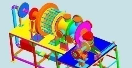
out. 30Scheme of Proton Linac Development
N
Normal
l Conducting
C d ti
LEHIPA-High current injector 20 DTL/
MeV, 30 mA CCDTL
High-
Proton IS RFQ DTL 100 MeV
SC
50 keV 3 MeV 20 MeV Low- SC linac Linac
SC-1 SC-2
Design
g completed
p and fabrication is in p
progress
g
1 GeV
3-MeV RFQ
ECR Ion Source
31
Proton beam dumpSummary
• Maximize the Energy Potential of Nuclear Fuel Material
through use of Closed Fuel Cycle & Thorium
• Development of FBR is a key component in realizing high
level of electricity generation in India, needed for
meeting its large demands
• Development of Th based Nuclear Energy systems is a
high priority in India
• India would pursue R&D to implement ADS for
sustainable nuclear power program.
•
IIndia
di wouldld like
lik to
t invite
i it and d participate
ti i t ini
international R&D activities- on accelerator,
nuclear data , spallation target and fuel cycle
options. 32Acknowledgements Dr. S. S. Kapoor Dr. S. B. Degweker Shri. P.K.Nema Dr. P. Singh
You can also read