Speech Transfer System - Installation & User Guide - Contacta Inc
←
→
Page content transcription
If your browser does not render page correctly, please read the page content below
Speech Transfer System
          Bridge Bar Kit | Surface Mounted Kit | Flush Mounted Kit |
Slimline Bridge Bar Kit | Curved Microphone Kit | Dual Overhead Speaker Kit

                   Installation &
                    User Guide
                               March 2019
Contents
Product Overview 3
Components 3
Installation Instructions 7
Speaker & Microphone Kit Installation 8
Staff Side Installation 8
Customer Side Installation 9
- Bridge Bar Kit 9
- Surface Mounted Kit 11
- Flush Mounted Kit 12
- Slimline Bridge Bar Kit 14
- Curved Microphone Kit 16
- Dual Overhead Speaker Kit 17
Hearing Loop Installation 18
Amplifier Setup 19
Using the System 21
Troubleshooting 23
Contacta has a policy of continuous product development, and therefore small specification
changes may not be reflected in this manual. Images, labels, packaging, accessories and
product colors are subject to change without notice.
2Product Overview
Speech transfer systems provide assistance for clear communication where
normal speech is impaired by use of glass, a security screen or other similar
barriers.
There is a hearing loop facility included, providing additional assistance for
hearing device wearers.
Components
General Components
1. Installation and User Manual 5. Power Supply
2. Amplifier 6. Hearing Loop Aerial
3. Hearing Loop Sticker 7. Mounting Bracket
4. IEC Lead
3 6
1
7
2 4 5
Fixing Kit:
• Adhesive Clip x 10
• No.6 x 1/2” Countersunk Screws x 15
• P-Clips x 6
Speaker & Microphone Components
There will also be one of the following speaker and microphone kits:
• Bridge Bar Kit (see page 4)
• Surface Mounted Kit (see page 4)
• Flush Mounted Kit (see page 5)
• Slimline Bridge Bar Kit (see page 5)
• Curved Microphone Kit (see page 6)
• Dual Overhead Speaker Kit (see page 6)
3Speaker and Microphone Kits
Bridge Bar Kit - STS-K001L-G/B
(For installation see page 9)
1. Staff Microphone
2. Bridge Bar
1
2
Surface Mounted Kit - STS-K002L-G/B
(For installation see page 11)
1. Staff Microphone
2. Surface Mounted Speaker and Microphone
1
2
4Flush Mounted Kit - STS-K003L
(For installation see page 12)
1. Staff Microphone
2. Flush Speakers and Microphone
1
2
Slimline Bridge Bar Kit - STS-K060
(For installation see page 14)
1. Staff Microphone
2. Slimline Bridge Bar
1 2
5Curved Microphone Kit - STS-K035-B/B-RH/G-RH/G-LH
(For installation see page 16)
1. Staff Microphone
2. Curved Speaker and Microphone
1
2
Dual Overhead Speaker Kit - STS-K015-01
(For installation see page 17)
1. Staff Microphone
2. Recessed Bridge Bar
3. Dual Overhead Speakers
1 3
2
6Installation Instructions
We recommend that installation is carried out by a qualified engineer,
adhering to relevant standards.
Check the contents of the box to familiarize yourself with the components.
The staff microphone and amplifier should be installed on the staff side of the
counter. The customer speaker and microphone kits should be installed on
the customer side of the counter.
Follow all relevant instructions in the following order:
1. Speaker & Microphone Kit Installation.
a. Staff Side Installation (see page 8).
b. Customer Side Installation (see page 9).
2. Hearing Loop Installation (see page 18).
3. Amplifier Setup (see page 19).
4. Using the System (see page 21).
Recommended Tools
A basic toolkit recommended to install the system will include:
• Screwdrivers (Flat or Blade 2.5mm • Pliers
and Phillips Head PH2) • Tape Measure
• Battery or Mains Drill • Pencil or Marker Pen
• Drillbits: 2mm, 3mm, 5mm and 7mm • Torch
• Allen Key Set • Cable Ties
• Cable Tacking Gun (10mm) • Electrical Insulation Tape
• Wire Cutters/Strippers • Trunking
There may be a need for a router when installing the Flush Mounted Kit, and a
hacksaw for the Bridge Bar Kit or Slimline Bridge Bar Kit.
7Speaker & Microphone Kit Installation
Staff Side Installation Fixing points
1. Place the staff microphone on the staff side of the counter top, ensuring
that it does not cause an obstruction and is as close to staff as possible.
2. Place the amplifier under the staff counter, ensuring that it will not
obstruct staff when they are sitting.
3. Mark the four fixing points for the amplifier under the counter.
4. Drill and fix the amplifier in place using the supplied screws.
5. Use the cable management hole in the counter to run the staff
microphone cable back to the amplifier. If there is not already a cable
management hole, drill in a suitable location near the rear of the counter.
6. Install the amplifier’s power supply close to a power socket outlet using
the supplied mounting bracket and fixing screws.
Amplifier Connections
After all relevant components have been installed, connect all green plugs to
the sockets at the rear of the amplifier following the layout detailed below.
Power input
connection
Use power supply
through ground
supply only
Hearing loop aerial Staff microphone connection
Customer speaker connection Customer microphone connection
Staff speaker connection Confidence LED (if required) for status alerts
and fault detection
Line in connection for
external audio source LED connection or alert tone (if required)
Confidence LED to confirm the system is powered
8 or an alert tone for the attention of staffCustomer Side Installation
Bridge Bar Kit
1. Place the bridge bar on the counter top in a central location over the
pass-through tray.
2. Disassemble the speaker pods by undoing the screws and removing the
housing.
Housing Allen grub
fixing points screws
Cable
Allen grub holes
screws
Fixing points
3. If the bridge bar needs to be narrowed, calculate the width required
(minimum: 450mm) with the following steps:
a. Locate the allen grub screws on the mounting bracket and loosen
them to allow the brackets to slide along the tube.
b. Slide the brackets inwards until the desired width is obtained. Ensure
the microphone stem is an equal distance from both brackets.
c. If necessary, use a hacksaw to cut the bridge bar to the counter’s
required length. Be careful to avoid any damage to wiring.
d. Ensure the brackets are in the desired location and re-tighten the
grub screws.
4. Place the mounting brackets adjacent to either side of the pass-through.
They should be approximately 2-3mm away from the screen.
95. Mark the four fixing points and two cable management holes to be
drilled.
6. Ensure there will be access to retrieve the cables, then drill the holes.
7. Fix the speaker pods to the counter and feed the wiring through the
cable management holes.
8. Refit the housing using the screws previously removed.
9. Route all the cabling neatly to the amplifier location on the staff side.
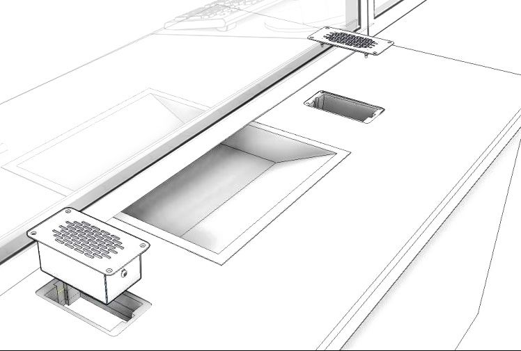
10Surface Mounted Kit
1. Place the speaker and microphone pods on the customer side of the
counter top.
2. Disassemble the speaker and microphone pods by undoing the screws
and removing the housing.
3. Place the mounting brackets adjacent to either side of the
pass-through tray, at least 2-3mm away from the screen.
4. Mark the four fixing points and two cable holes to be drilled.
5. Ensure there will be access to retrieve the cables and drill the holes.
Housing
fixing points
Cable holes
Fixing points
6. Fix the speaker and microphone pods to the counter, and feed the wires
through the cable management holes.
7. Refit the housing with previously removed screws.
8. Route all cabling neatly to the amplifier location on the staff side.
11Flush Mounted Kit
1. Check that there is at least 50mm of free space below the customer side
of the counter top for the speaker and microphone pods.
2. Ensure there is access to the wiring under the counter once installed.
3. Mark the cut-out dimensions in the diagram below onto the counter top
twice, adjacent to either side of the pass-through tray. The recommended
distance between each cut-out marking is 500mm.
Recess (hatched)
R6 107
52 Cut-out 15 54 65
5
97.5
120
4. Use a router to cut out two areas for the flush mounted speaker and
microphone pods, routed to a depth of 1.5mm.
Speaker and microphone pod
container cut-out
125. Mark the four fixing points per
cut out and drill the holes.
6. Run the cables from the pods
Fixing
through the counter top. points
7. Secure both pods to the
counter using the screws Fixing
provided. points
8. Route all the cabling neatly to
the amplifier location on the staff side.
13Slimline Bridge Bar Kit
1. Place the bridge bar on the counter top in a central location, positioned
over the pass-through tray.
2. Disassemble the speaker pods by undoing the screws and removing the
housing.
3. Place the mounting brackets on the counter top an equal distance to the
center of the pass-through tray.
4. Place the stainless steel bridge bar strip between the brackets with each
end laying slightly inside the brackets.
5. If the bridge bar needs to be narrowed, use a hacksaw to cut it to the
required length.
6. Mark the four fixing points and two cable management holes to be
drilled.
Housing Housing Cable
fixing points fixing points hole
Cable
hole
Fixing
points
Fixing
points
7. Ensure there will be access to retrieve the cables and then drill the pilot
holes for the fixing screws.
8. Test the complete assembly by placing it in its intended position,
ensuring it sits flat against the surfaces.
149. Place the microphone assembly on the glass screen using the bridge bar
strip as a positioning guide, ensuring the microphone stem is vertical.
10. Lay the microphone cable in the groove on the back of the bridge bar
strip and feed it back to one of the brackets.
11. Carefully adhere the bridge bar strip to the screen frame, ensuring the
microphone cable stays in its groove.
12. Feed the wiring through the cable management holes.
13. Refit the housing using the screws previously removed.
14. Route all the cabling neatly to the amplifier location on the staff side.
15Curved Microphone Kit
1. Place the microphone and speaker unit on the customer side of the
counter top.
2. Disassemble the customer pod by undoing the screws and removing the
housing.
3. Place the mounting bracket on the counter:
a. If the microphone stem
curves to the left, place
the pod to the right of the
pass-through tray; if the stem
Housing
curves to the right, place it to
fixing
the left. points
Cable
b. Ensure the microphone is hole
positioned centrally over the
pass-through tray.
4. Mark the four fixings holes and Fixing
points
the cable management hole.
5. Ensure there will be access to retrieve the cables and then drill the holes.
6. Fix the customer pod to the counter and feed the wiring through the cable
hole.
7. Refit the housing using the screws previously removed.
8. Route all the cabling neatly to the amplifier location on the staff side.
16Dual Overhead Speaker Kit
1. Install the overhead speakers:
a. Find a location on the staff side
directly above the pass-through
tray. Ensure there is sufficient Fixing
space and no glass behind the points
drilling location.
b. Check the cable route to the amplifier situated under the counter.
Ensure there is access through the counter top and suitable cable
length. If neccesary, drill a cable hole through the rear of the
counter or extend cables.
c. Mark 2x fixing points to attach the overhead speakers.
d. Drill pilot holes and attach the speaker bracket assembly using
supplied screws.
e. Route the cable from the speaker back to the amplifier in a neat
and tidy fashion, using cable containment where required.
f. Repeat the above steps on the customer side of the counter.
2. Position the bridge bar unit on
the customer side of the counter
top, in a central location over Fixing
points
the pass-through tray.
3. Ensure the microphone and
bridge bar are flat against the
screen. Cable
hole
4. Mark the 2 fixing points and 1
cable hole ready for drilling.
Bridge Bar cover
5. Drill fixing points and a cable Cable fixing points
hole and attach the assembly hole
with the supplied screws.
7. Feed wiring through the cable hole back to the amplifier.
8. Attach the bridge bar cover using the provided fixing points and screws,
carefully avoiding damage to wiring.
17Hearing Loop Installation The aerial should be fixed under the desk-top or counter centrally on the customer side, one half mounted horizontally under the counter and the other half mounted vertically, facing the customer (as in the first scenario below). Position the aerial under the counter using either the provided P-clips or another fixing method of your choice. See the diagram below for recommended positioning. X X Ensure all hearing loop signage is displayed clearly. 18
t u O loV

                                                   t u O loV
atcatnoc                               Amplifier Setup

                            atcatnoc
           2 OC

                                          2 OC
 Our amplifier provides full open duplex communication and is compatible
 with all of our speech transfer systems. It features individual displays for staff
 or customer adjustments and individual fault lights for easy fault diagnosis.

 Overview of Front Panel Buttons
                    13A- STS

                                                   13A- STS
       Volume In                             Volume Out
 Increase and decrease                  Increase and decrease

           Vol In     Status             Vol Out                               STS-A31

                           1
                           2
                           3
                                                                                            On/Off
                      Status                                   CO2
           Vol In          4             Vol Out                               STS-A31
                           5
                           6
                           1
                           7
                           2
                           8
                           3                                   contacta                     Settings
                                                               CO2
                           4
                           5
                           6
                           7
                           8
                                                               contacta
 Engineers Mode
 Before entering engineers mode, cycle the power. To do this either:
    • Switch the power off at the wall socket and back on again
        or,
    • Remove the power connector and re-insert it
 To enter engineers mode, simultaneously press and release the following
 buttons within 20 seconds of cycling the power:
     • Settings button
     • Volume In increase button
     • Volume Out increase button
 The on/off and settings buttons in engineers mode operate as follows:

            Move to the next setup area                                   Save and exit engineers mode

 Please note:
 • Save and exit engineers mode after making any adjustments.
 • The amplifier will automatically exit engineers mode without saving if no
     buttons are pressed for 2 minutes.

                                                                                                       19
Setup Areas
Whilst in engineers mode, there are 3 editable setup areas. You will always
enter setup area 1 first. The green Volume In LED bar will flash to indicate
which setup area you are in.
Setup Area 1:
Maximum Volume Adjustment (LED 1 flashes)
Increase maximum Increase maximum
staff volume level customer volume level
Decrease maximum Decrease maximum
staff volume level customer volume level
Setup Area 2:
Ducking Adjustment (LED 2 flashes)
Increase Ducking on
ducking level (Vol Out LED 1 illuminates)
Decrease Ducking off
ducking level (Vol Out LED 1 turns off)
atcatnoc
Setup Area 3: 8
7atcatnoc
Hearing Loop Drive Adjustment (LED 3 flashes) 6
5
atcatn2oOCc 4
8
3
Increase drive LEDs illuminate to
7
2
6
2 OC
1
display loop drive
5
4
13A- STS 2 OC voltage
t u O l oV s3u ta tS n I l oV
Decrease drive 13A- STS 2
1
tuO
13A- STS t u O l oV sutatS n I l oV
The drive level should be adjusted so the red LED 8 is illuminated only when
there are peaks in the speech volume.
If the amplifier does not have a loop attached, you can turn off the red loop
fault LED 8 by adjusting the drive down to off.
Please note:
• If the amplifier detects an error in its settings memory it will restore itself
to factory default settings.
20Using the System
When powered and in normal operational mode the amplifier will display
Volume In LED 1 as steady green.
When the amplifier is switched off using the On/Off button, audio is muted
and LEDs are not illuminated; press any button to turn the amplifier on again.
To adjust the staff volume level:
• Press and hold the Volume In (+) or (-) buttons to increase or decrease the
level. The corresponding LED bar will show the volume setting.
To adjust the customer volume level:
• Press and hold the Volume Out (+) or (-) buttons to increase or decrease
the level. The corresponding LED bar will show the volume setting.
For best possible performance:
1. Ensure the customer and staff volumes are turned completely down.
2. Adjust staff volume (Volume In) to a comfortable level.
3. Increase customer volume (Volume Out) until feedback is heard.
4. Decrease customer volume (Volume Out) until feedback is just eliminated.
Once you have followed the above steps:
1. The staff microphone is best positioned no
more than 300mm away from the staff member.
2. Check the amplifier is fully functional by Staff
ensuring the red ‘fault’ light is NOT displaying. microphone
If there is insufficient volume even after you have
adjusted the volume controls, enter engineers mode and raise max volume
settings. Exit engineers mode and repeat initial setup.
The system is now ready to use.
Fault Diagnosis LEDs
• Volume In LED 8 will stay red if there is a
fault with the staff microphone.
• Volume Out LED 8 will stay red if there is a
fault with the customer microphone.
• Volume In LED 8 will flash red if there is a
fault with the loop (i.e. a broken aerial).
21Factory Default Settings
To return the amplifier the factory default settings:
1. Unplug the power supply and then reconnect it.
2. Press the On/Off button and Volume In (-) button together, then release.
3. The Volume In LED bar will have all LEDs illuminated, while the Volume
Out LED bar will display the firmware revision number in a fixed pattern
of LEDs. This indicates that default settings have been restored.
22Troubleshooting
Symptom Possible Fault Action
There is no 1) Power jack not plugged in or 1) Check power jack is firmly plugged
power faulty. in.
detected
through the 2) Plug fuse has blown. 2) Replace fuse. If it blows again,
amplifier (and replace the power supply unit.
there is power
at the socket). 3) Faulty power supply unit. 3) Replace the power supply unit.
4) Faulty amplifier. 4) Replace amplifier.
The red LED is 1) Constant red LED: 1) Ensure microphone is wired
illuminated on Staff or customer microphone fault. correctly and firmly plugged in. Try
front panel. alternative microphone to ensure
port is working.
2) Red LED comes on after speech: 2) Ensure induction loop connector is
Induction loop fault. wired correctly and firmly plugged in.
I can’t hear 1) Induction loop or microphone is 1 ) Check instructions for correct
audio through disconnected. connections and, if possible, check
the induction the hearing device with a known
loop. working hearing loop.
2) Loop tester has a fault. 2) Ensure loop tester has a new set
of batteries.
I can hear 1) Unscreened or poorly earthed 1) Switch off any third party
interference third party equipment is being used equipment to identify the source of
through in close proximity. interference.
speakers
(buzzing / 2) Internal volume gain set to high. 2) Access the amplifier engineers
whistling / mode to adjust the internal settings.
hissing).
3) Incorrect power supply being 3) Ensure that our grounded power
used. supply unit is connected.
Amplifier goes 1) Internal volume gain set to high. 1) Access the amplifier engineers
into feedback. mode to adjust the internal settings.
2) Microphone positioned too close 2) Move the microphone to a
to speaker. location further from the speaker.
Unit does not 1) Ambient noise in area is too high. 1) Switch off any air con systems,
go into power desktop fans and or computers to
saving mode. reduce ambient noise.
If no action is successful please seek assistance from
your distributor or a Contacta installer.
23Contact your local
distributor for further
information.
Contacta, Inc.
(616) 392-3400
support@contactainc.com
www.contactainc.comYou can also read