Underfloor Heating Instructions - County Building Supplies
←
→
Page content transcription
If your browser does not render page correctly, please read the page content below
Underfloor Heating Instructions
02 Electric Underfloor Heating

Contents

General Information 				03

Preparation 					04

Installation 					05

Measuring Values with the Multimeter 		   09

Connecting the Thermostat 				10

Technical Data 					10

Operating Instructions 				11
Electric Underfloor Heating 03

General information

This electric underfloor heating mat is manufactured to the
highest standard. For your guarantee to be valid the mat must
be fully installed in accordance with the installation manual.
Carefully read the instructions prior to installation and ensure
that you have the correct tools and materials. Final connection
to the mains must be undertaken by a qualified electrician.

•   Check that the heating mat is the correct size for the         •   The sensor must be installed in the middle of a cable loop
    floor area to be heated and that there is sufficient               for efficient operation. Ensure that the sensor is installed
    power available. The mat should not be positioned over             at least min. 50 cm from hidden radiator and water pipes,
    expansion joints.                                                  drains and electrical wiring.

•   If multiple mats are installed please ensure that the          •   The sensor MUST be installed in the sensor pipe, with
    maximum capacity of the thermostat is not exceeded. The            the end cap fitted to avoid the sensor becoming stuck. If
    thermostat should be installed by a qualified electrician.         the sensor ever needs to be replaced it can then easily be
    The power supply must be turned off during installation.           removed.

•   Each mat is tested at the factory and has a unique             •   A sufficiently strong and thick compression resistant
    inspection card. Every mat is tested at 4000 volt. You             floor, with or without reinforcing, must be applied on
    must check the mat after each installation phase, in               wood and insulation. Please ensure the floor is suitably
    order to know at which phase any defect occurs.                    stabilized.

•   The heating cable, attached to the glass fibre net, must       •   The electric heating mat is guaranteed for 10 years. The
    NOT be broken. The mats must NOT be laid over each                 thermostat is guaranteed for 2 years. The guarantee does
    other and the heating cables must NEVER cross each                 not apply to damage caused by external factors and/or
    other. The cable junction (where the power supply cable            incorrect installation.
    joins the heating cable) is just within the heating mat.

•   The mat has 1 connecting cable, which is 5 metres in
    length. The connector cable MUST NOT be shortened by
    more than 3 metres. The power supply must be turned off
    during installation.

•   The heating mat is 3 - 4 mm thick and must be incorporated
    in an adhesive or screed suitable for floor heating. Check
    the manufacturer’s data.

•   A distance from the wall of 10 cm is recommended. The
    mat should never be installed under fixed objects like
    kitchen units, baths or showers and must be able to give
    off its warmth freely.

•   The mat should only be incorporated into the free floor/
    wall areas. Please contact your heating engineer who
    will advise the heating requirement of the room.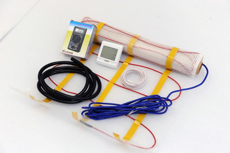
04 Electric Underfloor Heating
Preparation
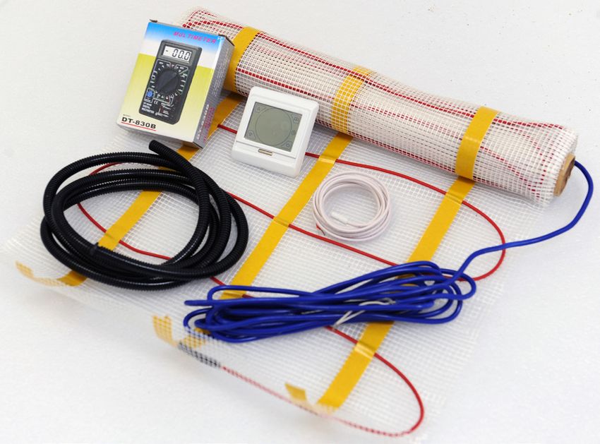
Check the contents of the box before starting. A complete set
will consist of:
• Heating mat with connecting wire.
• Control card.
• Digital clock thermostat incl. floor sensor.
• Flexible sensor pipe.
• Multimeter.
• Installation manual.
Materials Needed
• Electric Underfloor Heating kit. • Plastic glue comb with approx. 6mm teeth.
• Flexible tile adhesive or levelling / screed and grout • Electrical junction box (min 40mm deep).
suitable for floor heating. • Power outlet with RCD 30mA.
• Flexible cement and cement gun for expansion joints • Adhesive or double sided tape (for screeded floors).
along the walls.
• Approx. 2 m flexible electrical piping (16mm).
Position of Thermostat
Determine where the thermostat is to be placed for ease of
operation. A standard electrical junction box with a minimum
depth of 40mm will be needed. Mount as in (fig 1) with suitable
sheathing/conduit to allow plastering after installation.
Cut a groove in the floor for the floor sensor pipe 2 cm deep
(fig 2), and feed the sensor through the flexible pipe capping
the end to avoid the sensor becoming stuck (fig 3). The sensor
must always remain in the flexible pipe. If the sensor ever Fig. 1 Fig. 2
needs to be replaced it can then easily be removed.
Ensure that all work surfaces are flat, clean, and free of dust
and grease.
Fig. 3
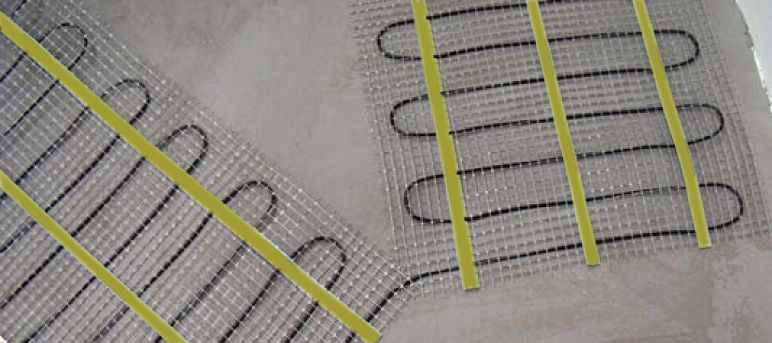
Electric Underfloor Heating 05

Installation
Tile Cement
Lay the heating mat with the heating cable facing down so that
only the glass fibre netting is visible (fig 4).

Screed
Lay the heating mat with the heating cable facing up, to
prevent the glass fibre netting ‘floating’ on the levelling
screed. If necessary, the mat can also be attached using double
sided adhesive tape.

General
Determine how the matting must be laid. The glass fibre
netting can be cut between the cable loops and folded over.
Avoid damaging the cable. There are many possible variations
when installing, please see page 8.

Fig. 4                                                            Fig. 5

Fig. 6                                                            Fig. 7

Measuring out the Mat

Test mat before commencing installation to ensure that
the values recorded agree with the manufactures figures on
the control card. This will show there are no faults. Allow a
distance from the wall of 10 cm when rolling out the matting.
If the mat is too long it can be folded by cutting through the
fibre netting without damaging the heating cable (Fig 5,6&7).
This can be repeated a number of times to suit the requirements
of the room (examples are shown on page 8). If the mat is still
too long the cable can be cut loose from the fibre netting and
installed in loose strips as shown. The loose cables must be
looped at least 4 cm from each other, and should not touch or
cross. Retest the mat when it has been laid.
06 Electric Underfloor Heating

Installing in Tile Cement
•         Apply a first layer of cement of 0.5 to 1 cm thick and           •         Smooth it over and allow it to dry.
          approximately 55 cm wide (fig 8).                                •         Test the mat again with a multimeter (see page 9) and
•         Feed the end of the connecting cable through the electrical                write down the readings on the control card.
          piping to the thermostat (fig 9).                                •         Then apply a second layer of tile cement taking care to
•         Roll the mat out over the tile cement with the cable facing                avoid air bubbles. Use a plastic tile cement comb to avoid
          downwards (fig 10).                                                        damaging the heating mat (fig 12).
•         Softly push the mat down with a wooden spatula or gloves         •         Fix tiles to the adhesive (fig 13).
          and spread the tile cement that oozes through the mat (fig11).

Fig. 8                                                                     Fig. 9

Fig. 10                                                                    Fig. 11

Fig. 12                                                                    Fig. 13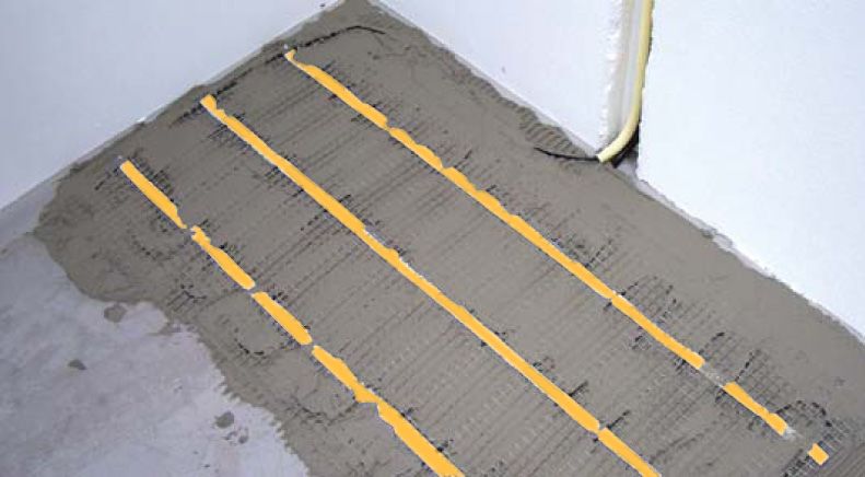
Electric Underfloor Heating 07

Installing in Screed
Position the mat as described on page 5. Attach the mat to
the floor with adhesive or double sided tape (as shown).

Test the mat again with a multimeter (see page 9) and write
down the readings on the control card.

Please check that the screed is suitable for floor heating and
follow the laying instructions of the manufacturer, observing
drying times.

PLEASE NOTE: Applying 2 separate levelling layers, one on
top of the other, is NOT RECOMMENDED as it can cause
unnecessary tension in the floor.

Fig. 14                                                          Fig. 15

Fig. 16                                                          Fig. 17
08 Electric Underfloor Heating
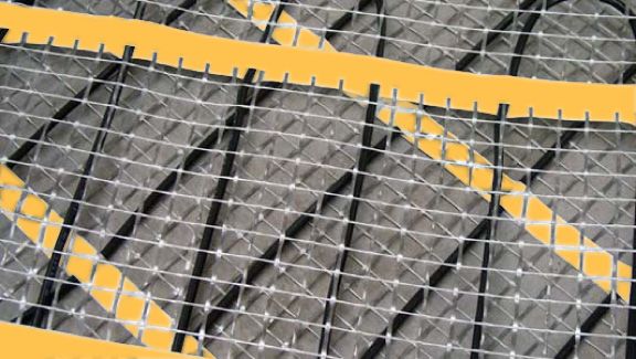
Installation: Laying Variations
The mat can be laid in several ways, as illustrated in diagram below:
Never cut the heating cables
Never overlay the heating cables
PLEASE NOTE: Heating will only occur where the
mat has been installed.
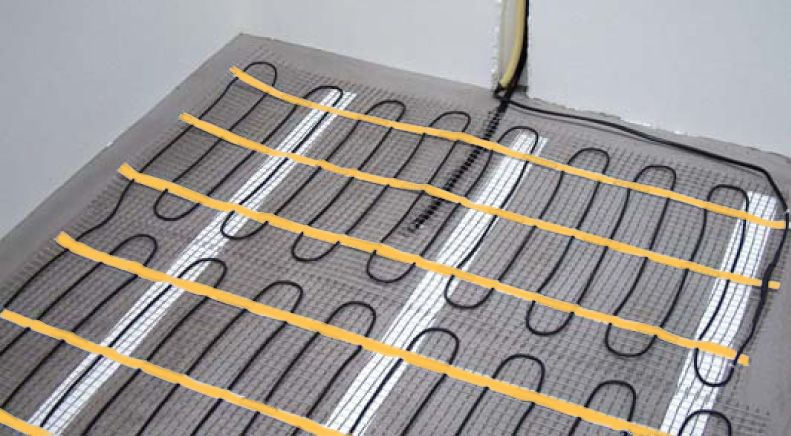
Installation: Laying Example
Please note that where there is no matting installed the floor
will not be heated.
If the mat is too long the cable can be cut loose from the fibre
netting and installed in loose strips. The loose cables must be
looped at least 4 cm from each other. They must not touch or
cross each other. See above.
The sensor must be installed in the middle of a cable loop for
optimal temperature registration. Ensure that the sensor is
installed well clear (min. 50 cm) of hidden radiator and water
pipes, drains and electrical wiring.
The mat must never be installed under fixed objects like wall
units, kitchen units, baths, or showers and must be able to give
off its warmth without being unimpeded.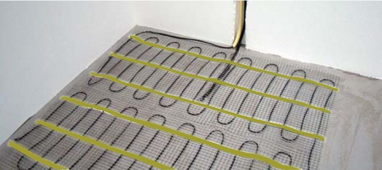
Electric Underfloor Heating 09

Testing with Multimeter

•         Connect the wires to the multimeter (fig 18).               •         Connect the RED probe to one of the connection wires
                                                                                and the BLACK probe to the Earth wire (fig 21). Earth
•         Turn the knob of the multimeter to the Ohm 2000 position.             wire has no sheath. Repeat this step with the RED probe to
          (fig 19).                                                             the other connection and BLACK probe to the Earth wire.

•         Connect the red and black probe to the connection wires     •         Reading on the multimeter now should be ‘1’. If you
          (fig 20). The connection wires (Phase and Neutral) have a             read any resisance there is a possible break in the wires.
          clear insulation sheath.                                              Please check again. Please call 01902 387000 and stop
                                                                                installation if reading still shows resistance.
•         Do not touch the wires when measuring. Check readings
          according the control card which was attached to the
          heating mat. If readings are not within the limits shown
          please call 01902 387000 and stop installation.

Fig. 18                                                               Fig. 19

Fig. 20                                                               Fig. 21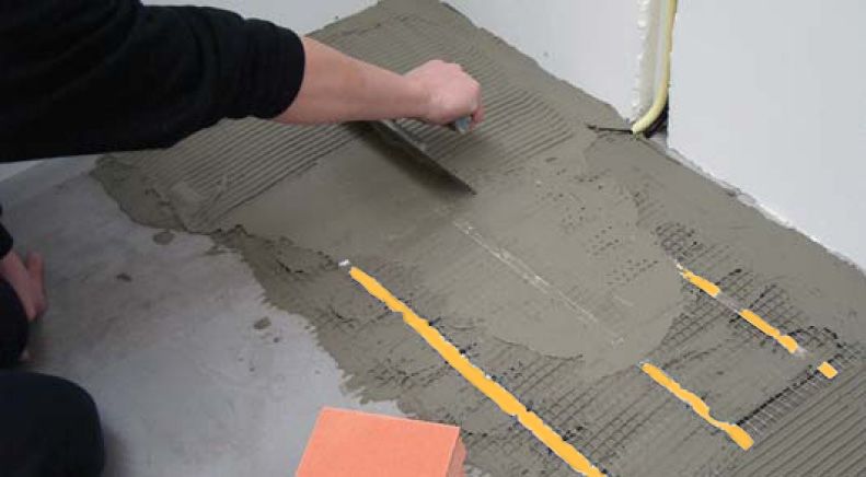
10 Electric Underfloor Heating
Connecting the Thermostat
During installation/de-installation of the thermostat the
electricity should always be turned off at the mains.
Installation must be carried out by a qualified electrician
in accordance with the IEE regulations.

Cover:
Check that the electricity is turned off. Remove the display
housing by inserting a blunt, suitable instrument into the square
hole at the bottom of the thermostat and exerting pressure
(fig 22), Then once again using a blunt, suitable instrument
exerting pressure in a upward motion disengage retaining bar
(fig 23). Both the display housing and the cover plate can then
be removed.

Wiring (see wiring diagram below fig 24):
• 3, 4 are used for the connection wires from the heating
   cable. The connection wires (Phase and Neutral) have a
                                                                           Thermostat
   white insulation sheath, and it does not matter which one
   goes into terminal 3 and which into terminal 4.
•   1 (Phase-Brown/Red), 2 (Neutral-Blue/Black) are for the
   power supply.
• The earth wire from the matting is unsheathed and needs
   to be sheathed before connection to the mains earth.
•   6 and 7 are for connecting the sensor.

Installation:
Place the thermostat mounting plate in the right position and
fasten this with two screws. Replace the display unit fixing the
retaining bar back into the locked position(fig 23) then gently            Fig. 22                       Fig. 23
replace the display housing. As soon as the power is turned
back on the screen will illuminate and the thermostat can be
used. In case of a newly installed floor, allow at least three
weeks drying out period.
         1            2        3          4      5       6            7

        LIVE       NEUTRAL     N1         L1           SENSOR    SENSOR

         L            N             16A
             AC230V
                                                      Underfloor Heating
                                                           Sensor
6.0 Technical Data
                                                  Heat outputs
                                                                           Fig. 24
        Type m2              Wattage           Amps         Ohms
          1m   2
                              150W              .65             353
         1.5m2                225W              .97             237
          2m2                 300W             1.30             177                  Power Supply          230V - 16Amp
         2.5m2                375W             1.63             141
          3m2                 450W             1.96             117                  Max. Capacity         3000W
         3.5m2                525W             2.28             101
          4m2                 600W             2.61              88                  Temp Range            5oC ~ 90oC
         4.5m2                675W             2.93              78
          5m2                 750W             3.26              71
                                                                                     Protection Rating     IP20
          6m2                 900W             3.91              59
          7m2                 1050W            4.56              50
                                                                                     Warranty              2 Years
          8m2
          9m2
                              1200W
                              1350W
                                               5.22
                                               5.86
                                                                 44
                                                                 39
                                                                                     Examination           CE
         10m2                 1500W            6.52              35
         11m2                 1650W            7.17              32
         12m2                 1800W            7.83              29
Electric Underfloor Heating 11
Installation: Programming thermostatic timer
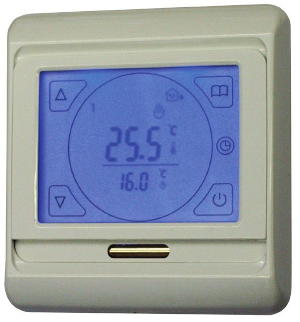
General information Daily use of the thermostat:
This thermostat is designed specially for electrical floor Clock controlled programme mode
heating. The floor sensor is supplied standard with the system. The week has been split into 3 cycles, the thermostat will
Please study these guidelines carefully before installation and opperate automatically according to the programmed
use. Save these instructions for possible later use. temperature and time. Clock controlled programme mode is
activated by pressing the key.
Direction for use
Turn on the power after having checked the installation & Manual clock controlled
instructions carefully. The screen will light up for the first time The temperature can be temporarily changed for a single
and will display 0Ff (OFF). period, this mode temperature is reset at the next cycle, and
the thermostat will return to scheduled program. This mode is
First activate the floor sensor and day off mode : entered by adjusting the temperature using the & keys
This can be done from the first activation screen while 0Ff is during Clock controlled programme mode.
displayed on the screen. Press in conjunction with to
enter the sensor setting menu, press once again to enter Manual mode
setting 2SEN sensor mode using the or keys select the The scheduled program is overridden, set the temperature
out mode for the under floor sensor, then press the key until according to your individual requirements and the thermostat
you reach 6PRG to select from 5/2,6/1 or 7 day mode, using will operate at this temperature until you alter the setting
the or to choose, to exit menu press . manually. Manual mode is activated by pressing the key.
Set the time: Key-lock Function
From the ON position press and hold the key for 5 seconds Press both the & keys for 5 seconds to engage/disengage
to enter the time and day settings*: the “Key-lock” function( symbol appears meaning “Key-
lock” function is activated, symbol disappears when “Key-
• & to select the minutes “flashing” press lock” function is deactivated)
• & to select the hours “flashing” press
• & to select the day “flashing” press to complete
*There is limited time to set the time, if it times out start the Programming the on/off cycle (quick referrence)
operation from the beginning.
Factory set defaults
Programming the on/off cycle:
Key Cycle Symbol Time Temperature
From the ON position press and hold the key for 5 seconds
to enter the programming section (The programming section On 06:00 200C
will disengage after 25 seconds if there are no other key
Set operating temperature
Off 08:00 150C
Set the start & end time
strokes). The days will be displayed and the time setting for
Day 1-5
On 11:30 150C
the first part of cycle 1:
Off 12:30 150C
• & to select the on time press
On 17:00 220C
• & to select operating temperature press
• & to select the off time press Off 22:00 150C
• & to select the set back* temperature press On 08:00 220C
Day 6-7
Off 23:00 150C
*Set back recommended to be 50C below operating
temperature. This will prevent the floor having to be heated up
Key
from cold, and will help response time’s.
On, cycle 1
Repeat the steps above for cycles 2&3 pressing at the end Off, cycle 1
of cycle 3 the day off* settings will now be displayed. On, cycle 2
Off, cycle 2
• & to select the on time press On, cycle 3
• & to select operating temperature press Off, cycle 3
• & to select the off time press
Heating On
• & to select the set back temperature press
Key-Lock function activated
To exit the programming menu press . This completes the SEN Set sensor mode
setting of the daily operating. PRG Set day off mode
On & Off
*Day off setting will only be displayed if you have choosen 5/2
or 6/1 from the day off mode (6PRG).THE HEATED TOWEL RAIL COMPANY
VOGUE (UK) LIMITED
STRAWBERRY LANE, WILLENHALL
WEST MIDLANDS, WV13 3RS, UNITED KINGDOM
T: +44 (0) 1902 387000 F: +44 (0) 1902 387001
E: info@vogueuk.co.uk w: www.vogueuk.co.ukYou can also read