MONITORING OF THE GEAR WEAR OF A WIND TUR- BINE GEARBOX IN A TRANSIENT OPERATION
←
→
Page content transcription
If your browser does not render page correctly, please read the page content below
The 21st International Congress on Sound and Vibration
                                             13-17 July, 2014, Beijing/China

   MONITORING OF THE GEAR WEAR OF A WIND TUR-
   BINE GEARBOX IN A TRANSIENT OPERATION
   Jin-Ho Bae and Jeong-Guon Ih
   Center for Noise and Vibration Control (NoViC), Division of Mechanical Engineering, Ko-
   rea Advanced Institute of Science and Technology (KAIST), Daejeon, Korea
    e-mail: J.G.Ih@kaist.ac.kr
   Yun-Ho Seo
   Division of System Dynamics, Korea Institute of Machinery & Materials (KIMM), Daejeon,
   Korea
   Jong-Hwa Lee
   NARU EMS Co., Ltd., Daejeon, Korea

   During the wind turbine operation, the random variation of wind speed causes a fluctuated
   operation of wind turbine. In such a harsh transient operation condition, the gears transmit-
   ting the rotational energy will experience a severe load change and the gear life will be quick-
   ly shortened. In this work, it is intended to diagnose the level of gear teeth wear of a wind
   turbine gearbox in a transient operation. Two indicators are suggested to quantify the wear
   amount. First, the percentage of exceeding alarm level is used to quantify how many times
   the vibration amplitudes for varying RPM exceed 99.5% confidence interval of the healthy
   condition to indicate the existence of wear. Second, the maximum overshoot value of mean
   energy-difference is used to indicate the severity of wear condition. To calculate these indica-
   tors, one needs to identify the magnitudes of harmonics of gear meshing frequency. However,
   such harmonics are also time-varying, so an appropriate order tracking algorithm should be
   adopted to trace the harmonic components adapting to a transient speed variation. To this end,
   the STFT using the variable frequency resolution technique is employed. For the validation
   purpose, a gearbox with 1:90 speed ratio is tested. To compare the normal and wear condi-
   tions, the statistical distribution in normal condition is measured first. Among various proba-
   bility distribution functions describing the vibration history, it is concluded from the chi-
   square goodness of fit test that the chi-square distribution is best fitted to the variation. The
   percentage of exceeding alarm level and maximum overshoot value of mean energy-
   difference are calculated as 38% and 25 dB at wear condition, respectively; while 0% and 10
   dB at normal condition. From such big difference in indicator values, a clearly decision is
   made that the gear teeth are in severe wear condition.

1. Introduction
      The wind turbine gearbox fluctuates randomly in operation due to the wind speed variation,
the gear teeth life will be shortened by the load variation. Because the gear teeth contact periodi-
cally with the driven gear to transfer the rotational energy, the time-varying vibration of the gearbox

ICSV21, Beijing, China, 13-17 July 2014                                                                1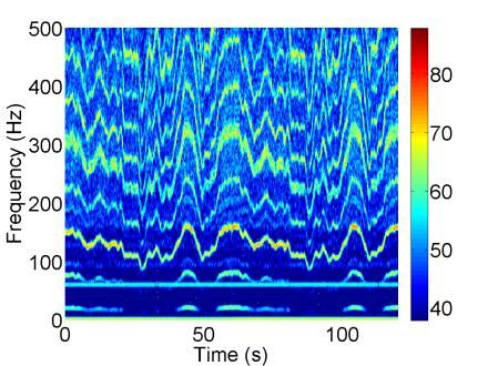
21st International Congress on Sound and Vibration (ICSV21), Beijing, China, 13-17 July 2014
appears as the spectral harmonics of the gear mesh frequency (GMF) of the drive shaft. Thus, one
can diagnose the gear condition by monitoring the harmonic amplitudes of the gear mesh frequen-
cies. Conventional methods dealing with stationary condition are not suitable for the wind turbine
gearbox in transient condition1,2. In this work, a monitoring method which would be proper for di-
agnosing the gear wear condition in transient operation is suggested. To diagnose the gear condition,
the order amplitudes of GMF in healthy condition is first traced from time-varying vibration signal
to obtain the statistical distribution. The order amplitudes in RPM domain are analyzed by introduc-
ing an order tracking algorithm using the short time Fourier transform using variable frequency
resolution (VFR-STFT), which was developed for the sound quality analysis3,4, while the chi-square
(2) goodness of fit test is employed for the assurance of the appropriateness of the statistical
model5. For the judgement of the gear health condition, two condition indicators are also suggested.
2. Suggestion of condition indicators for wear monitoring
Condition indicators are used to quantify or identify the fault condition. Conventional tech-
niques monitor the change of statistical parameters such as skewness and kurtosis to diagnose the
gear fault1, 2. However, those indicators are not proper for the wind turbine gearbox operating in
transient condition.
To diagnose the wear of a gear in transient condition, two condition indicators are suggested
by comparing the change of the order amplitude of GMF, which is traced by using an order tracking
method. First, the Percentage of Exceeding Alarm level (PEA) is suggested to check the number of
times in which the order amplitudes exceed 99.5% confidence interval of the healthy condition.
99.5% confidence interval means that the possibility that the signal is in healthy condition is 99.5%.
Because this confidence interval is related to the type I error, this error can be reduced by setting the
significant level as 0.05. The PEA is defined as
N exceed
PEA % 100, (1)
N RPM
where Nexceed denotes the number of RPM range exceeding 99.5% confidence interval in healthy
condition, NRPM is the total number of RPM range.
Second, the Maximum Overshoot value of Mean Energy-difference (MOME) is also sug-
gested to diagnose the gear fault. With the progress of the gear wear, the order amplitude of the
GMF increases6. Monitoring the maximum value of difference level between the monitored and the
standard mean signal, one can quantify the severity of wear condition. This indicator is MOME, and
it is written as
MOME % max LRPM , (2)
A
2
LRPM 10 log10 M ,RPM
, (3)
AS ,RPM
where LRPM represents the mean-difference level at each RPM, AM,RPM and AS,RPM the monitored and
standard mean signal at each RPM respectively. Because the energy difference between monitored
and standard mean signal can be obtained by using this indicator, the severity of wear condition is
more quantitatively calculated.
ICSV21, Beijing, China, 13-17 July 2014 2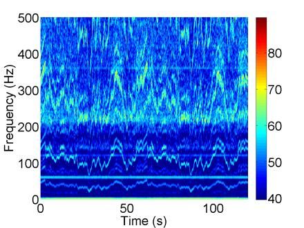
21st International Congress on Sound and Vibration (ICSV21), Beijing, China, 13-17 July 2014

3. Application: 5 kW wind turbine gearbox simulator
       A test in the wind turbine simulator is conducted, which is a device virtually replicating actual
wind environment. The wind turbine simulator consists of a operation part, a gearbox part, and a
generator part. In this study, the wear condition of the 2nd planetary gear in the 5 kW wind turbine
gearbox simulator works on fault diagnosis, and the gear wear is generated by driving gearbox at
about 5243 RPM during the 16 hours. This simulator gearbox has a 1:90 speed ratio, and the con-
figurations of wind turbine gearbox simulator are displayed in Fig. 1.
       The measurement position of accelerometer (PCB, 352C33) in gearbox is near the 2nd plane-
tary gear in horizontal axis. RPM and torque are measured by an encoder sensor (Ono Sokki,
MP981) and a torque sensor (SETech, YDR) at the high speed shaft to measure the variations of the
rotating speed.
       This simulator was operated at the virtual wind speed, which is determined from the empirical
wind model7. Experiment is conducted 10 times to set the statistical distribution in healthy condi-
tion and 2 times to diagnose a wear condition. Figure 2 shows operation conditions of the simulator
for 60 seconds.
                                                                       Encoder sensor
                                           2nd gear train
                                                                     (Ono sokki, MP981)

                                                                          Motor

                                                                     High Speed Shaft
                                                                  Torque sensor
                  Low Speed Shaft                                (SETech, YDR)

                                      Planetary gearbox (1:90)            Accelerometer
                                                                          (PCB, 352C33)

                 Figure 1. Measurement setup for a 5 kW wind turbine gearbox simulator.

     (a)                                 (b)                                  (c)

 Figure 2. Operation conditions for the 5 kW wind turbine gearbox simulator: (a) simulated wind speed, (b)
                                   measured RPM, (c) measured power.

3.1 Identification of order amplitude of GMF using order tracking
      Because the generated vibration energy of the 2nd planetary gear appears at the harmonics of
     nd
the 2 planetary GMF, the order amplitude of GMF should be monitored to diagnose the gear con-
dition. To get a fine time and frequency resolution, this work uses an order tracking algorithm using
VFR-STFT method, which was suggested in sound quality analysis3, 4. This method is similar with
STFT algorithm and can obtain the fine frequency resolution at fixed time resolution by employing
the algorithms for down sampling and linear interpolation. Considering the GMF change rate as
0.74 Hz during 0.01 s, the time and frequency resolution are determined as 0.01 s and about 1.0 Hz
respectively. Table 1 shows signal condition for VFR-STFT method.

ICSV21, Beijing, China, 13-17 July 2014                                                                  3
21st International Congress on Sound and Vibration (ICSV21), Beijing, China, 13-17 July 2014
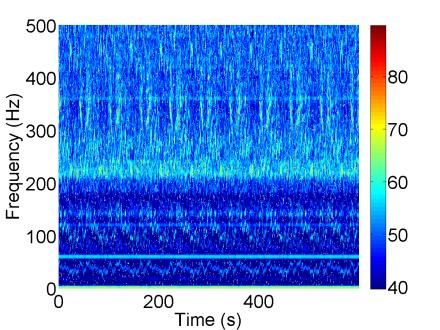
After obtaining the time-frequency map of vibration signal in gearbox, the harmonics of the
nd
2 planetary GMF are extracted by using the measured RPM signal, which is simultaneously meas-
ured with vibration signal. In this work, the 3 cases are considered to diagnose the gear fault; the
first case is for setting a standard in healthy condition by conducting the experiment for 10 times,
the second and the third cases are for monitoring a signal in healthy and wear condition by conduct-
ing the 2 times test. Each test condition is shown as Fig. 2.
Figure 3 represents the time-frequency map at each case. Using this time-frequency map and
measured RPM signal, one can trace the order amplitude of the 2nd planetary GMF in transient con-
dition. According to GL guidelines8, the number of harmonics to diagnose the gear fault is sug-
gested at least 1-4 harmonics. In this work, the first four orders of the 2nd planetary GMF are con-
sidered to monitor the fault condition. Figure 4 depicts RPM based order tracking results of the 2nd
order of the 2nd planetary GMF at each case. Because the RPM based order tracking results has sta-
tistical characteristics, the statistical distribution should be set to make a standard of healthy gear
condition. Here, a solid line is the mean signals at each RPM, and a dash line means 99.5% confi-
dence interval, which is determined by using a selected distribution in healthy condition.
Table 1. Signal processing conditions for the order tracking using VFR-STFT.
VFR-STFT
Sampling frequency (kHz) 25.6
Overlap / Window 75 % / Flat-top
Number of FFT 1024
Down sampling steps 4
Time resolution (s) 0.01
Frequency resolution (Hz)
1.56
(0 ~ 1000 Hz)
(a) (b) (c)
Figure 3. Time-frequency maps obtained by the VFR-STFT method: (a) a standard signal (healthy condi-
tion), (b) a monitoring signal in healthy condition, (c) a monitoring signal in wear condition.
(a) (b) (c)
Figure 4. Order tracking results in RPM domain at the 2nd order of the 2nd planetary GMF; ──, mean; ─ ─,
99.5% confidence interval: (a) a standard in healthy condition, (b) a signal in healthy condition, (c) a signal
in wear condition.
ICSV21, Beijing, China, 13-17 July 2014 421st International Congress on Sound and Vibration (ICSV21), Beijing, China, 13-17 July 2014
3.2 Statistical distribution of the order amplitude in healthy condition
One can diagnose the gear fault by comparing a monitored signal with the standard signal.
The statistical distribution is selected by comparing actual distribution, which consists of the ob-
served order amplitude, and 99.5% confidence intervals in RPM domain are calculated by using
selected distribution.
The chi-square goodness of fit test can find the best distribution function from the observed
order amplitude. This goodness of fit test can be written as5
Fi fi
2
n
2
, Fi NPi , (4, 5)
i 1 Fi
where χ2 denotes the chi-square value consisting of the observed frequency Fi and the expected fre-
quency fi, n is the total number of bines, Fi the observed frequency representing the total number of
the order amplitude N and expected probability density function Pi. To test the suitability of statisti-
cal distribution, hypotheses should be checked. If χ2 is smaller than χ2(n-1);α, hypothesis is rejected.
On the other hand, if χ2 is larger than χ2(n-1);α, hypothesis is accepted. Because the order amplitude
of GMF are always positive, chi-square and Rayleigh distributions for one-sided test are compared
with an actual distribution as displayed in Fig. 5. At the 2nd order amplitude at 11.5 RPM, the total
number of bines n is 20, and the total number of the order amplitude N is 1456. Table 2 represents
the results of the chi-square goodness of fit test at significance level α as 0.5. Among 4 distributions,
a chi-square distribution of 2 degree of freedom (DOF) is accepted, which has smaller χ2 than
χ219;0.05.
To reduce the type I error, a significance level for a confidence interval is set as 0.05, so
99.5% confidence intervals in RPM domain are displayed in Fig. 4(a).
Figure 5. Selection the statistical distribution by using χ2 goodness of fit test (the 2nd order amplitude at 11.5
RPM) ; , actual distribution; , χ2 of 1 DOF; , χ2 of 2 DOF; , χ2 of 3 DOF; , Rayleigh.
Table 2. The results of χ2 goodness of fit test (α = 0.5).
Distribution Calculated χ2 χ219;0.05 Result Rank
χ2 of 1 DOF 23.35 O 1
χ2 of 2 DOF 117.87 X 2
30.144
χ2 of 2 DOF 565.62 X 3
Rayleigh 1.75e+15 X 4
ICSV21, Beijing, China, 13-17 July 2014 521st International Congress on Sound and Vibration (ICSV21), Beijing, China, 13-17 July 2014
3.3 Monitoring of the gear condition by using the suggested condition indicators
Exceeding Alarm level (PEA) and the Maximum Overshoot value of Mean Energy-difference
(MOME) are suggested as the condition indicators to diagnose the wear of planetary gear. Figure
6(a) shows PEA results at each harmonic in healthy and wear gear condition. One can observe that
the all value of PEA in healthy condition is 0%. On the other hand, PEA value of each harmonic is
larger than 0%, and PEA of the 1st and the 2nd order much higher than that of the 3rd and the 4th or-
der. Because this indicator can check whether or not the gear fault exists, it is difficult to diagnose
other fault. The MOME values at each harmonic are calculated and shown in Fig. 6(b). The solid
line is 99.5% confidence intervals at each order. Among the 4 harmonics, the maximum values of
MOME in healthy and wear condition are 10 dB and 25 dB respectively. MOME value of healthy
gear is smaller than 99.5% confidence interval, but that of the wear of a gear larger than 99.5% con-
fidence interval. Because the vibration level increases when the wear fault progress8, other fault
conditions can be diagnosed by using MOME indicator.
(a) (b)
Figure 6. Condition monitoring at a planetary gear; , monitoring a mean signal in healthy condition; ,
monitoring a mean signal in wear condition; , 99.5% confidence interval: (a) percentage of exceeding
alarm levels, (b) maximum overshoot value of mean energy-difference.
4. Conclusions
Generated vibration signal at the wind turbine gearbox is in the transient condition due to its
random operation. To diagnose the gear fault of wind turbine gearbox, a proper fault diagnosis
method in transient condition is required. This work diagnoses the wear of 5 kW wind turbine gear-
box simulator, and experiment is repeatedly conducted to set the standard for healthy condition, and
2 times to monitor the gear in healthy and wear condition.
According to experiment in healthy condition, the statistical distribution is selected by using
the chi-square goodness of fit test. Among the variable distribution functions in this signal condition,
a chi-square distribution of 5 DOF is the best fit, and 99.5% confidence intervals in RPM domain is
determined by using this selected distribution function. The experiment in healthy and wear condi-
tion are conducted 2 times to compare the monitored and standard mean signal. Because the moni-
tored mean signal in healthy condition is in the 99.5% confidence interval, all values of Percentage
of Exceeding Alarm level and the maximum value of Maximum Overshoot value of Mean Energy-
difference are 0% and 10 dB respectively. In the case of wear condition, all values of Percentage of
Exceeding Alarm level are larger than 0% and the maximum value of Maximum Overshoot value of
Mean Energy-difference is 38 dB. The existence of wear can be indicated by analyzing the Percent-
age of Exceeding Alarm level. However, this indicator can only be able to check the existence of
the wear. It is difficult to quantify the severity of wear condition. To solve this problem, Maximum
Overshoot value of Mean Energy-difference is suggested to define that how much difference be-
ICSV21, Beijing, China, 13-17 July 2014 621st International Congress on Sound and Vibration (ICSV21), Beijing, China, 13-17 July 2014
tween the monitored and standard mean signal are. The severity of wear condition can be quantified
by using this indicator.
Acknowledgments
This work was partially supported by BK21 Plus project, NRF grants (No.
2012R1A2A2A01009874 and 2013006603), and KEPCO (No. 2011T100100307).
REFERENCE
1
Vecer, P., Kreidl, M. and Smid, R. Condition indicators for gearbox condition monitoring sys-
tems, Acta Plytec., 45 (6), 35-46 (2005).
2
Cong, F., Chen, J. and Dong, G. Spectral kurtosis based on AR model for fault diagnosis and
condition monitoring of rolling bearing, J. of Mech. Sci. Tech., 26, 301–306 (2012).
3
Jeong, H. and Ih, J.-G. Implementation of a new algorithm using the STFT with variable fre-
quency resolution for the time frequency auditory model, J. of the Audio Eng. Soc., 4, 240-
250 (1999).
4
Bae, J.-H., Ih, J.-G. and Kim, S.-R. Precise order tracking analysis of time-varying vibro-
acoustic signature from rotating machines, Proc. of the 21st ICA, Montrėal, Quėbec, Canada,
2–7 June (2013).
5
Bendat, J. S. and Piersol, A. G. Random data – analysis and measurement procedures, John
Wiley & Sons, fourth edition, 79-108 (2010).
6
Vecer, P., Kreidl, M. and Smid, R. Condition indicators for gearbox condition monitoring sys-
tem, Acta Polytechnica, 45, 35-43 (2005).
7
Jonkman, B. J. TurSim Use’s Guide: Version 1.50, Technical report, NREL National Renew-
able Energy Laboratory (2009).
8
Anon. Guideline for the certification of condition monitoring systems for wind turbines, IV
Rules and Guidelines Industrial Service, Germanischer Lloyd Industrial Services GmbH
(2007).
ICSV21, Beijing, China, 13-17 July 2014 7You can also read