PRIMATE STARTLE SYSTEM - SOF-828P USER'S MANUAL - Med Associates Product Manual
←
→
Page content transcription
If your browser does not render page correctly, please read the page content below
instrumentation and software for research

 PRIMATE STARTLE SYSTEM
 SOF-828P
 USER’S MANUAL

DOC-004
Rev. 2.7

Copyright ©2021
All Rights Reserved

Med Associates, Inc.
P.O. Box 319
St. Albans, Vermont 05478

Phone: 802.527.2343
Fax: 802.527.5095
www.med-associates.com
This page intentionally left blank
MED ASSOCIATES, INC.                                                                                              SO F - 8 2 8 P P R I M AT E ST AR T L E

Table of Contents
Chapter 1 | Introduction ................................................................................................ 1
Chapter 2 | Hardware ..................................................................................................... 3
General Computer Environment .................................................................................................. 3
Hardware Guide ............................................................................................................................. 3
Cable Guide .................................................................................................................................... 6
Air Puff System Hardware ............................................................................................................ 6
Hardware Assembly ....................................................................................................................... 7
Wiring Instructions ........................................................................................................................ 8
Plumbing/Wiring Instructions for the Air Puff System........................................................ 12
Chapter 3 | Use of Restaint Chair .............................................................................. 13
Chapter 4 | Calibration Procedures ........................................................................... 15
Audio Calibration ........................................................................................................................ 15
Calibrating Chamber 1 Audio ..................................................................................................... 15
St art l e W hit e Noise Calibration ........................................................................................... 16
Background Noise Calibration .................................................................................................... 16
Tone Frequency Calibration ....................................................................................................... 17
Input Calibration .......................................................................................................................... 18
Steps for Calibrating the Load Cell............................................................................................ 18
Gain Set Too Low ........................................................................................................................ 20
Gain Set Too High ....................................................................................................................... 21
Appendix A | Contact Information............................................................................. 22

                                                                           - iii -                               DOC-004 Rev. 2.7 Copyright © 2021
                                                                                                                               Med Associates, Inc.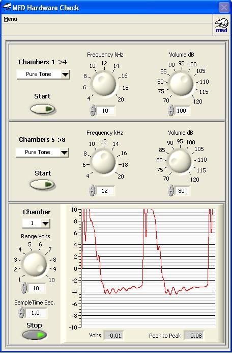
MED ASSOCIATES, INC.                                          SO F - 8 2 8 P P R I M AT E ST AR T L E

                                        Notes
_____________________________________________________________________________________
_____________________________________________________________________________________
_____________________________________________________________________________________
_____________________________________________________________________________________
_____________________________________________________________________________________
_____________________________________________________________________________________
_____________________________________________________________________________________
_____________________________________________________________________________________
_____________________________________________________________________________________
_____________________________________________________________________________________
_____________________________________________________________________________________
_____________________________________________________________________________________
_____________________________________________________________________________________
_____________________________________________________________________________________
_____________________________________________________________________________________
_____________________________________________________________________________________

                                      Diagrams

                                        - iv -               DOC-004 Rev. 2.7 Copyright © 2021
                                                                           Med Associates, Inc.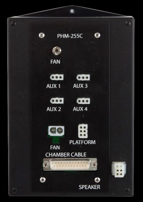
MED ASSOCIATES, INC.                                                              SO F - 8 2 8 P P R I M AT E ST AR T L E

CHAPTER 1 | INTRODUCTION
The startle reflex is a motor response to an intense and unexpected stimulus. The neuroanatomy of the
acoustic startle reflex is well-characterized and is often studied in humans, rodents, and primates to
measure sensorimotor processing, emotional state, and/or attention. Alterations in the startle reflex
response are often studied between animal strains, and within the pre-pulse inhibition of startle (PPI) and
fear-potentiated startle (FPS) paradigms.
Our Primate Startle System allows users to obtain accurate quantification of the acoustic startle reflex in
primates. The Startle Reflex software package is designed for use with Med Associates modules to
produce stimuli, collect response data, plot data to the screen, and perform waveform analysis.
Please thoroughly read this manual prior to setup to gain an understanding of the system. Should any
problems or questions arise, the technical support staff at Med Associates is available for assistance.

    Figure 1-1 - Sound Attenuating Cubicle (SAC) with Restraint Chair and Interface Controller.

                                                      -1-                        DOC-004 Rev. 2.7 Copyright © 2021
                                                                                               Med Associates, Inc.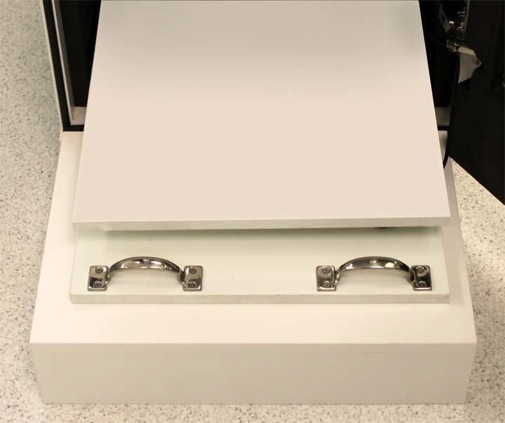
MED ASSOCIATES, INC. SO F - 8 2 8 P P R I M AT E ST AR T L E
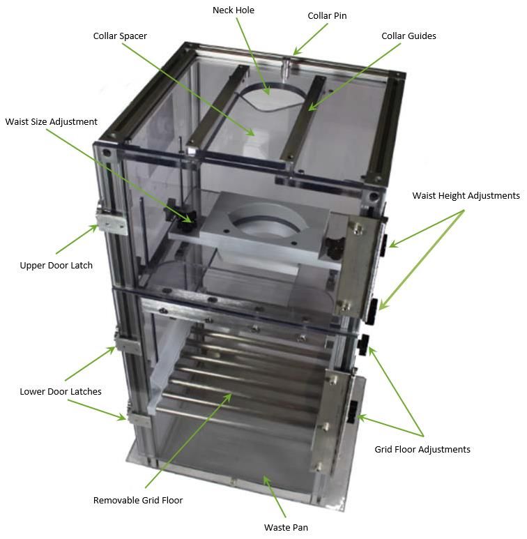
NOTE: Remove 4 shipping stabilizer shims before installing Restraint chair.
Figure 1-2 - SAC interior showing shipping stabilizer shims.
-2- DOC-004 Rev. 2.7 Copyright © 2021
Med Associates, Inc.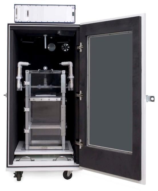
MED ASSOCIATES, INC.                                                         SO F - 8 2 8 P P R I M AT E ST AR T L E

CHAPTER 2 | HARDWARE

Gener al Computer Environment
The minimum recommended system is as follows:
       •   2.0 GHz or higher with one available PCI slot and one available USB 2.0 port.
       •   Windows 7 or later (32 & 64-bit)

   NOTE: Always switch off power prior to performing work on the computer or interface cabinets.
   Serious damage may occur if power is on.

Hardwar e Gui de
   Figure 2-1 - Interface Cabinet with ANL-729, ANL-925E and two ANL-925D Cards.

   Figure 2-2 – Back of computer (DIG-744E card)

                                                   -3-                      DOC-004 Rev. 2.7 Copyright © 2021
                                                                                          Med Associates, Inc.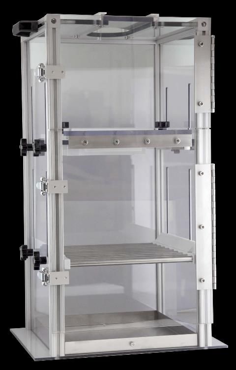
MED ASSOCIATES, INC.                                                           SO F - 8 2 8 P P R I M AT E ST AR T L E

   Figure 2-3 - PHM-255C Primate Startle Stimulus Controller (Mounted on the Top of the SAC).

   Figure 2-4 – Acoustic Startle Speaker Assembly (Mounted Inside the SAC).

   Figure 2-5 – ENV-226D 3 Channel Fader Controller

   Figure 2-6 - PHM-250D Load Cell Amplifier and Potentiometer Trimmer Tool.

                                                      -4-                      DOC-004 Rev. 2.7 Copyright © 2021
                                                                                             Med Associates, Inc.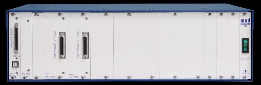
MED ASSOCIATES, INC.                                                            SO F - 8 2 8 P P R I M AT E ST AR T L E

   Figure 2-7 – Restraint Chair.

   Figure 2-8 – Load Cell Platform.

   Figure 2-9 - ANL-930 Standalone Sound Pressure Level Measurement Package .

                                                  -5-                       DOC-004 Rev. 2.7 Copyright © 2021
                                                                                          Med Associates, Inc.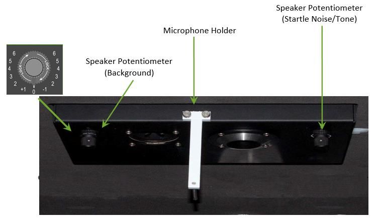
MED ASSOCIATES, INC.                                                         SO F - 8 2 8 P P R I M AT E ST AR T L E

Cable G uide
   Figure 2-10 – Interface Cables.

SG-210CB - SmartCtrl™ Cable 25’         SG-244-68 – NI Shielded Cable         SG-USB-6 – USB A to B Cable

Air Puff System Hardware
   Figure 2-11 - Solenoid with Pneumatic Tubing for Air System and Optional Compressor.

                                                   -6-                       DOC-004 Rev. 2.7 Copyright © 2021
                                                                                           Med Associates, Inc.
MED ASSOCIATES, INC. SO F - 8 2 8 P P R I M AT E ST AR T L E
Hardwar e Assembly
Open the primate startle Sound Attenuating Cubicle (SAC) door and place the load cell platform inside.
Orient the load cell platform so that the amplifier cable is on the right.
Route the amplifier cable through the hole in the right side of the SAC, as shown in Figure 2-12. Place the
restraint chair (shown in Figure 2-7) on top of the load cell platform.
Figure 2-12 - Open Primate Startle SAC with Load Cell Platform and Restraint Chair.
NOTE: The amplifier cable in the lower right corner of the SAC can become pinched
when sliding the platform back inside the SAC. Use caution to avoid damage to the cable.
Figure 2-13 – Amplifier Cable.
-7- DOC-004 Rev. 2.7 Copyright © 2021
Med Associates, Inc.MED ASSOCIATES, INC. SO F - 8 2 8 P P R I M AT E ST AR T L E
Wiring Instructions
NOTE: Some wiring may have been completed prior to shipping. Be sure that power to all
hardware is disconnected prior to completing any wiring.
1. Using the SG-244-68 NI (National Instruments) cable, connect the DIG-744E card
(back of the computer) to the ANALOG DATA connector on the ANL-729 (in the
interface cabinet).
2. Using an SG-USB-6 USB cable, connect the USB connector on the front of the ANL-729 to
any available USB connector on the computer.
3. Using an SG-210CB 25’ SmartCtrl cable, connect the PHM-255C (top of the Primate Startle
Cubicle) to the CHAMBER CABLE connector on the ANL-925D (in the interface cabinet).
-8- DOC-004 Rev. 2.7 Copyright © 2021
Med Associates, Inc.MED ASSOCIATES, INC. SO F - 8 2 8 P P R I M AT E ST AR T L E
4. Open the grommet plate on the back of the SAC by loosening the two screws
indicated below. The wiring in the remaining steps should be routed through this plate.
5. Connect the Load Cell cable to the LOAD CELL connector on the PHM-250D.
6. Connect the POWER/SIGNAL OUT on the PHM-250D to the PLATFORM cable on the
PHM-255C.
-9- DOC-004 Rev. 2.7 Copyright © 2021
Med Associates, Inc.MED ASSOCIATES, INC. SO F - 8 2 8 P P R I M AT E ST AR T L E
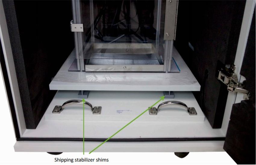
7. Connect the AUX 2 connector on the PHM-255C using a series of SG-216* cables to the
ENV226D 3 Channel Fader Controller IN connectors as seen below. Then connect the
lights in no specific order to the ENV226D 3 Channel Fader Controller OUT connectors.
8. Connect the fan (mounted to the back of the SAC) to the FAN connector on the PHM-255C.
- 10 - DOC-004 Rev. 2.7 Copyright © 2021
Med Associates, Inc.MED ASSOCIATES, INC. SO F - 8 2 8 P P R I M AT E ST AR T L E
9. Connect the speaker assembly (mounted inside the SAC, Figure 2-4) to the 6-pin
connector on the PHM-255C.
10. Close the grommet plate and tighten the screws, shown below.
11. Repeat steps for each additional chamber.
- 11 - DOC-004 Rev. 2.7 Copyright © 2021
Med Associates, Inc.MED ASSOCIATES, INC. SO F - 8 2 8 P P R I M AT E ST AR T L E
Plumbing/Wiring I nstructions for the Air Puff System
1. Using the 50’ length of pneumatic tubing, connect the compressor to the solenoid.
2. Using the 10’ length of pneumatic tubing, connect the solenoid to the air system connector
inside of the Primate Startle SAC. The tubing should be run through the hole in the back of
the SAC.
NOTE: The air compressor can cause incorrect data if it is operating too close to the
Startle Chamber. If possible, the air compressor should not be in the same room.
3. Connect the 2-pin solenoid cable to the extension cable connected to AUX 1 on the
PHM-255C.
4. Plug in the compressor, turn it on and set the air pressure to the desired pressure
(about 80-100 psi). Refer to manufacturer’s instructions for operation and maintenance of
compressor.
- 12 - DOC-004 Rev. 2.7 Copyright © 2021
Med Associates, Inc.MED ASSOCIATES, INC. SO F - 8 2 8 P P R I M AT E ST AR T L E
CHAPTER 3 | USE OF RESTAINT CHAI R
The Restraint Chair accommodates 10.2cm and 12.7cm collars. (Purchased separately from a third
party vendor.) Adjust the collar slots for the appropriate size of the collar.
Figure 3-1 – Collar Guide Adjustment.
Remove the collar spacer and plate. Place the animal onto the restraint chair. Use the collar pin to
temporarily hold the collar in the collar guides while installing the collar spacer. (See Figure 3-2 &
Figure 3-3.)
Figure 3-2 – Collar Spacers.
- 13 - DOC-004 Rev. 2.7 Copyright © 2021
Med Associates, Inc.MED ASSOCIATES, INC. SO F - 8 2 8 P P R I M AT E ST AR T L E
Figure 3-3 – Restraint Chair with Labeled Features.
- 14 - DOC-004 Rev. 2.7 Copyright © 2021
Med Associates, Inc.MED ASSOCIATES, INC. SO F - 8 2 8 P P R I M AT E ST AR T L E
CHAPTER 4 | CALIBRATION P ROCEDURES
After the Primate Startle system has been set up, it is important to test the system to ensure
that it is functioning properly. A complete calibration procedure is performed prior to shipping;
however, it is necessary to calibrate the system for each new protocol and/or set of animals.
Audio calibration includes adjustment of volume. Calibration of the load cell amplification will
depend on the animal’s level of response. The Hardware menu in Advanced Startle contains
utilities for complete testing and calibration of all hardware.
Audio Calibration
Some audio frequencies are produced at naturally different volumes than others. With the
Hardware Check utility and the ANL-930 Standalone Sound Pressure Level Measurement
Package, the speaker's frequency response can be tested, and the results can be used to correct
for this. Calibrate based on the sound parameters (decibel (dB) and frequency (Hz) level) of the
desired experiment protocol.
This system includes all components necessary for calibrating the speakers to generate
reproducible startle stimuli. For more information regarding the use of the ANL-930 Standalone
Sound Pressure Level Measurement Package, refer to DOC-315 ANL-930 Sound Pressure Level
Meter Manual.
Calibrati ng Chamber 1 Au dio
1. Utilizing the ANL-930, mount the microphone holder inside the Primate Startle SAC
with the microphone pointed towards the speaker assembly, see Figure 4-1.
2. Set the dials on the speaker assembly to the center (0 Gain) of the adjustment range.
Referring to Figure 4-1, turn the two speaker potentiometer dials located at rear of
the SAC. This is an adjustment setting of 0dB.
Figure 4-1 – Speaker Assembly with Potentiometers and Microphone Holder.
- 15 - DOC-004 Rev. 2.7 Copyright © 2021
Med Associates, Inc.MED ASSOCIATES, INC. SO F - 8 2 8 P P R I M AT E ST AR T L E
3. Launch the Advanced Startle application. Select Menu | Hardware | Hardware Check
from the Advanced Startle drop menu. The Hardware Check shown in Figure 4-2 will
appear.
Figure 4-2 – Hardware Check Screen
St art l e W hit e Noise Calibrati on
4. Determine the Startle White Noise dB level appropriate for your protocol.
5. On the Hardware Check screen, choose Stimulus Type: Startle Noise from the drop
down, and set the Volume (dB) to 100dB and click Start.
6. Verify the dB level using the ANL-930 Sound Pressure Level Meter.
7. If the volume is incorrect by + or - 2 dB, adjust the Right speaker potentiometer (Figure
4-1) to achieve the correct value. Turn counterclockwise to decrease volume and
clockwise to increase volume.
Background N oise Cali brati on
8. Determine the Background Noise dB level appropriate for your protocol.
9. On the Hardware Check screen, choose Stimulus Type: Background Noise from the drop
down, and set the Volume (dB) to 100dB and click Start.
10. Verify the dB level using the ANL-930 Sound Pressure Level Meter.
11. If the volume is incorrect by + or - 2 dB, adjust the Right speaker potentiometer (Figure
4-1) to achieve the correct value. Turn counterclockwise to decrease volume and
clockwise to increase volume.
- 16 - DOC-004 Rev. 2.7 Copyright © 2021
Med Associates, Inc.MED ASSOCIATES, INC. SO F - 8 2 8 P P R I M AT E ST AR T L E
Tone Frequency Calibr ation
12. Determine the frequency and dB level for tone that will be used in your protocol.
13. On the Hardware Check screen, choose Stimulus Type: Pure Tone, and adjust to the
desired Frequency (Hz) and Volume (dB) and click Start.
14. Observe the dB reading on the ANL-930 Sound Pressure Level Meter.
15. If the dB level is higher or lower than the dB level set in the Hardware Check screen,
note the difference and use this value to offset the desired dB level within the protocol.
EXAMPLE: If the dB level is set to 100 and the actual reading is 98, increase the desired dB level
by 2 (the dB offset is -2dB). So, if the protocol requires a dB level of 70dB, enter a value of 72dB in
the protocol. See Figure 4-4.
Figure 4-3 – Protocol Example.
16. Repeat steps 12-15 for each frequency that will be used in the protocol.
17. When completed, remove microphone.
NOTE: The human ear will incorrectly perceive certain frequencies to be louder than others
even though a sound meter will show the same loudness level for both.
- 17 - DOC-004 Rev. 2.7 Copyright © 2021
Med Associates, Inc.MED ASSOCIATES, INC. SO F - 8 2 8 P P R I M AT E ST AR T L E
Input Calibr ation
Proper calibration of the load cell ensures consistent measurements across multiple chambers.
Using the following calibration procedure ensures that an exhibited force, namely Startle response,
will result in similar data output in all chambers.
The input calibration procedure has two components:
• Adjust Tare (offset) so that the signal amplitude is zero over a range of gain settings.
The Tare should be adjusted while only the restraint chair is on the load cell platform.
This ensures a consistent reading of zero is obtained with no applied force.
• Apply a known weight and adjust the gain so that the signal amplitude is at the same
reference value in all chambers. This procedure ensures that a given amount of force will
result in the same signal in all chambers.
Steps for Calibr ating the Load Cell
1. Start the Advanced Startle software, and click Menu | Hardware | Hardware Checks, see
Figure 4-4.
2. Set the Chamber number on the bottom section of the screen to the correct Chamber.
Figure 4-4 – Hardware Check Screen.
3. Set the Range Volts setting to 10 Volts.
4. Set the Sample Time to 0.2 seconds.
5. Verify that the empty restraint chair is sitting correctly on the Primate Startle platform, and
that it is the only thing on the platform.
- 18 - DOC-004 Rev. 2.7 Copyright © 2021
Med Associates, Inc.MED ASSOCIATES, INC. SO F - 8 2 8 P P R I M AT E ST AR T L E
6. Set the GAIN dial on the front of the PHM-250D amplifier to 1.0.
Figure 4-5 – PHM-250D Amplifier.
7. Set the CAL/RUN switch on the PHM-250D to CAL.
8. Click Start in the Hardware Check screen. The signal from the PHM-250D platform
amplifier is displayed as a red line, see Figure 4-4.
9. Use the potentiometer trimmer tool to adjust the TARE potentiometer located on the
front of the PHM-250D amplifier until the signal is as close to zero as possible. Some
slight fluctuations are normal, as the signal from the load cell is affected by
environmental conditions such as air currents and vibrations.
10. Turn the TARE potentiometer slowly clockwise to increase the output amplitude and
move the red line up. Turn the TARE potentiometer slowly counter-clockwise to
decrease the output amplitude.
NOTE: Turn the TARE potentiometer very SLOWLY, as it is possible to turn it too far and not be
able to adjust the signal any further. If you have turned the potentiometer too far, you may hear
a faint click upon each revolution. If this occurs, slowly turn in the opposite direction.
11. Once the zero adjustment is made at a gain of 1.0, increase the GAIN knob on the front of
the PHM-250D amplifier to 2.0.
12. Adjust the TARE potentiometer until the signal is as close to zero as possible.
13. Increase the GAIN knob on the front of the PHM-250D amplifier to 3.0.
14. Adjust the TARE potentiometer until the signal is as close to zero as possible.
15. Repeat steps 8-10, increasing gain in increments, until the amplifier is tared at the
highest setting desired. The maximum gain on the PHM-250D is 10.0, but typical
experiments operate at a gain of 5.0-6.0.
16. Decrease the GAIN to 1.0. The load cell signal should stay near zero, even while you are
decreasing the gain.
- 19 - DOC-004 Rev. 2.7 Copyright © 2021
Med Associates, Inc.MED ASSOCIATES, INC. SO F - 8 2 8 P P R I M AT E ST AR T L E
17. Place the calibration weight (Figure 4-6) on top of the Restraint Chair.
Figure 4-6 – Restraint Chair with Weight Applied.
18. Adjust the gain knob on the front of the PHM-250D until the signal is at 8 Volts.
19. Remove calibration weight from the Restraint Chair and verify that the signal returns to
zero.
20. Set the CAL/RUN switch on the PHM-250D to RUN.
21. Repeat this procedure for each startle platform.
NOTE: To ensure the input calibration is within the ideal range for experiments, it is recommended
to run a few test experiments with animals within an expected startle response range before
acquiring data. Different individual animals or groups of animals may have different startle
ranges or weights.
Gain Set Too Low
If gain is set too low, the system may report reduced or absent startle response. To fix this, re- calibrate
to a higher voltage (9-10 Volts). If higher gain is necessary, a test weight of less mass may be used
during calibration. The same weight must be used with all chambers during calibration.
- 20 - DOC-004 Rev. 2.7 Copyright © 2021
Med Associates, Inc.MED ASSOCIATES, INC. SO F - 8 2 8 P P R I M AT E ST AR T L E
Gain Set Too High
If gain is set too high, you may observe “clipping”, which occurs when the amplifier is attempting to
produce a response that exceeds its maximum voltage capability. To fix this, re- calibrate using to a lower
voltage level.
Figure 4-7 – Clipping Example.
- 21 - DOC-004 Rev. 2.7 Copyright © 2021
Med Associates, Inc.MED ASSOCIATES, INC. SO F - 8 2 8 P P R I M AT E ST AR T L E
APPENDIX A | CONTACT INFORMAT ION
Please contact Med Associates, Inc. for information regarding any of our products.
For Technical questions, email support@med-associates.com.
For Sales questions, email sales@med-associates.com.
Visit our website at www.med-associates.com.
- 22 - DOC-004 Rev. 2.7 Copyright © 2021
Med Associates, Inc.You can also read