GUIDE FOR LIGHTNING PROTECTION OF POWER OVER ETHERNET (POE) DEVICES INSTALLED OUTDOORS - COPYRIGHT DANIEL G ASHTON 2021
←
→
Page content transcription
If your browser does not render page correctly, please read the page content below
Guide for Lightning Protection of Power
 over Ethernet (PoE) Devices Installed
 Outdoors

Copyright © Daniel G Ashton 2021
Abstract: Devices such as security cameras, when installed outside of a building,
 may be exposed to direct or indirect lightning strikes. These devices utilize a twisted
 pair ethernet cable to carry the signals and a DC feed to power the device. Devices
 placed on poles separate of a building are more likely to be struck by lightning.
 Some form of protection is necessary to prevent damage to the DC power feed and
 connected equipment. Several examples of protection methods are given.

 The document content is of a general nature only and is not intended to address the
 specific circumstances of any particular individual or entity; nor be necessarily
 comprehensive, complete, accurate or up to date; nor represent professional or
 legal advice.

Copyright © Daniel G Ashton 2021
Contents

 1.0 Introduction ...........................................................................................................4
 2.0 Definitions and Abbreviations ................................................................................4
 2.1 Definitions .............................................................................................................4
 2.2 Acronyms ..............................................................................................................5
 3.0 Overview ...............................................................................................................6
 3.1 PoE Devices Installed Outdoors ............................................................................6
 3.2 Lightning Protection System (LPS) ........................................................................7
 4.0 Exposed Versus Unexposed ...............................................................................10
 5.0 Power over Ethernet (PoE) Versus Power over Data Line (PoDL).......................13
 6.0 Basic Installation Overview..................................................................................14
 7.0 Device Grounding................................................................................................16
 8.0 Surge Protective Devices (SPD’s) .......................................................................17
 9.0 Recommended Lightning Protection for Externally Mounted Devices ..................18
 9.1 Security Cameras ................................................................................................18
 9.2 Ethernet (Fixed Wireless) Radio Systems ...........................................................22
 10.0 References ..........................................................................................................25

Copyright © Daniel G Ashton 2021
Guide for Lightning Protection of Power
over Ethernet (PoE) Devices Installed
Outdoors

 1.0 Introduction

 Devices such as security cameras, when installed outside of a building, may be
 exposed to direct or indirect lightning strikes. These devices utilize a twisted pair
 Ethernet cable to carry the signals and a DC feed to power the device. Devices
 placed on poles separate of a building are more likely to be struck by lightning.
 Some form of protection is necessary to prevent damage to the DC power feed and
 connected equipment. Several examples of protection methods are given.

 2.0 Definitions and Abbreviations

 2.1 Definitions

 For the purposes of this document, the following terms and definitions apply.

 Ground Potential Rise (GPR) is a phenomenon that occurs when large amounts of
 current enters the earth at a given point, such as in the case of a lightning strike.
 The closer to the lightning strike point, the greater the voltage and current.

 Lightning Protection System (LPS) a system designed to protect a structure from
 damage due to lightning strikes by intercepting such strikes and safely passing their
 high currents to ground. See NFPA 780® (9)

 Midspan PSE A device that adds voltage and current to an Ethernet circuit for the
 connected powered device (PD)

 Physical (layer) (PHY) The layer responsible for interfacing with the transmission
 medium. This includes conditioning signals received from the media access control
 (MAC) for transmitting to the medium and processing signals received from the
 medium for sending to the MAC.

 Power Over Ethernet (PoE) technology that provides power over LAN cables to
 connected powered devices without the need for batteries or AC outlets.

Copyright © Daniel G Ashton 2021
2.2 Acronyms

 AC Alternating current
 ACEG Alternating current equipment ground
 AWG American wire gauge
 DC Direct current
 EMI Electromagnetic interference
 GPR Ground potential rise
 IEEE Institute of Electrical and Electronics Engineers
 LAN Local area network
 LEMP Lightning Electromagnetic Pulse
 LPS Lightning protection system
 NEC® National Electrical Code
 NFPA® National Fire Protection Association
 NRTL Nationally recognized test laboratory
 PD Powered device
 PHY Physical layer (usually Ethernet transceiver)
 PoDL Power over data line
 PoE Power over Ethernet
 PSE Power source equipment
 RRH Remote radio heads
 SPD Surge protective device

Copyright © Daniel G Ashton 2021
3.0 Overview

 3.1 PoE Devices Installed Outdoors

 Traditionally security and communications equipment mounted on the exterior of
 buildings has been powered either by 120V AC or from a separate DC power
 source. In recent years, PoE technology has been used to power these types of
 devices (see Figure 1 for examples of PoE devices). These systems incorporate a
 PoE router or a Midspan power source equipment (PSE) to provide power to the
 device. These devices may be mounted under the eaves of the roof, over the eaves
 of the roof, on top of the roof or on a separate mounting structure such as a pole.
 This document will provide information to assist in protecting PoE devices installed
 where they may be exposed to lightning strikes, induction, and surges.

 Figure 1
 PoE Powering and Powered Device Examples

Copyright © Daniel G Ashton 2021
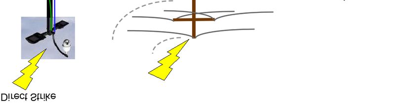
3.2 Lightning Protection System (LPS)

 When Lightning strikes, it can damage unprotected equipment by either a direct
 strike or through induction from the lightning electromagnetic pulse (LEMP) as
 illustrated in Figure 2. A well-engineered lightning protection system will help
 minimize this damage.

 Figure 2
 Lightning Strike Examples

Copyright © Daniel G Ashton 2021
A lightning protection system includes a network of air terminals, bonding
 conductors, and grounding electrodes designed to provide a low impedance path to
 ground for potential strikes. See NFPA 780® (9) and examples shown in Figures 3
 and 4.

 Lightning Protection System

 Main Conductor Air Terminal
 (lightning rod)

 Down conductor
 sized per
 NFPA 780 ®.

 LPS ground ring
 FIGURE 3
 Pitched Roof Lightning Protection System

Copyright © Daniel G Ashton 2021

Flat Roof Lightning Protection System

 Main Conductor/ Air Terminal (lightning Rod)
 Roof Top Ring

 Down Conductors

 LPS Ground Ring
 Figure 4
 Flat Roof Lightning Protection System

Copyright © Daniel G Ashton 2021
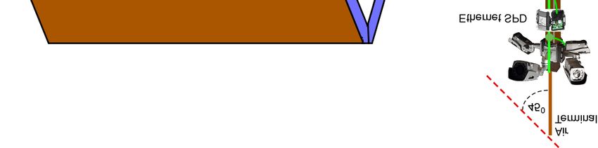
4.0 Exposed Versus Unexposed

 When metallic devices are installed outside of a building, they are exposed to the
 effects of lightning. When they are placed within the “zone of protection” of an LPS,
 the risk of a direct strike is greatly reduced. Two examples of a zone of protection
 are shown in Figure 5, where anything below the solid line would be considered
 protected.

 Figure 5
 ®
 Figures from NFPA 780 (9) Section 4.8 depicting a 45-degree and a
 63-degree angle from the vertical

 Per NFPA 780® (9) section 4.8.2.2, the zone of protection is delineated as a cone,
 with the apex located at the highest point of the strike termination device and its
 surface formed by a 45-degree or 63-degree angle from the vertical, based on the
 height of the strike termination device above the ground. See NFPA 780® section
 4.8 for additional details on the zone of protection. For a structure with an LPS on
 the roof, any device installed under the LPS should be considered within the “zone
 of protection”.

Copyright © Daniel G Ashton 2021
Any PoE powered device mounted above the roof line of a structure that does not
 have an LPS, would be considered fully exposed to a direct lightning strike and may
 need additional protection measures.

 Lightning caused ground potential rise (GPR) is another source of damage from
 lightning. Grounding and bonding, as laid out in section 7 of this document, will help
 minimize damage from lightning GPR.

 Ground potential rise [GPR] is a result of lightning striking the ground. Current flows
 away from the point where the lightning hits, creating potential gradients. The
 voltage at each point on the potential gradient can be calculated; but in general, the
 calculation is very complicated. In the simple case of uniform earth resistivity, the
 ground potential GP of the earth at a distance “r” from the point where a lightning
 strike enters the ground is given by equation (1).

 = (1)
 2

 Where ρ is the resistivity of the earth generally being a function of distance, angle,
 and depth], and I is the lightning current. The important feature of GP is that it falls
 off as 1/r. In the more general cases, it falls off as a power series in (1/r)n. For the
 simple case just discussed the potential gradient looks like the equipotential circles
 shown in Figure 6. Depending on the earth resistivity ρ and the current I, the
 potential difference between the lightning strike point and a remote ground can
 reach 10 kV or more, as Figure 6 shows. For a more extensive discussion of GPR,
 see references (3) and (9)

Copyright © Daniel G Ashton 2021
Figure 6
 Lightning GPR

Copyright © Daniel G Ashton 2021
5.0 Power over Ethernet (PoE) Versus Power over Data Line (PoDL)
 (1) PoE uses multiple paired conductors for power and data transmission (see (1) for
 more details). PoDL uses a single twisted pair of conductors for both power and
 data transmission (see IEEE P802.3bu (2) and “A Quick Walk Around the
 Block with PoDL” by Dwelley, D. (2015) (1) for more detail). Long Reach (up
 to 1000 m) PoDL is commonly used in industrial applications. Where a PoDL
 powered device (PD) is installed in a manner that exposes it to lightning strikes
 and surges, the contents of this document would apply.

 • In order to work, PoE
 requires (at least) two pairs
 connected between the pairs
 and the center tap.

 • PoDL requires only one pair
 which is connected with a
 lowpass/high pass band
 splitting network. It works
 with single-pair Ethernet.

 Figure 7
 PoE and PoDL basic design after IEEE P8023bu (6)

Copyright © Daniel G Ashton 2021
6.0 Basic Installation Overview

 A well-established practice is to install video surveillance cameras on building
 exteriors. Originally this required a coaxial cable and an AC power source for each
 camera. (See Figure 8) The AC electrical ground (ACEG) and the shield of the
 coaxial cable helped to mitigate the effects of lightning induced voltages.

 AC Power
 Coax to monitor

 Figure 8
 Traditional Surveillance Camera Installation

 With the advent of PoE powered devices, the need for a well shielded cable and an
 ACEG where eliminated. Lightning induced voltages may increase since a 24 AWG,
 non-shielded cable will have greater impedance than the combined coaxial cable
 shield and ACEG conductor. It should also be noted that the metallic shield on a
 twisted pair ethernet cable is an EMI shield and not designed to carry fault current.
 See Figures 9 through 11.

Copyright © Daniel G Ashton 2021
Figure 9
 PoE Surveillance Camera

 Figure 10
 PoE Ethernet Radio

Copyright © Daniel G Ashton 2021
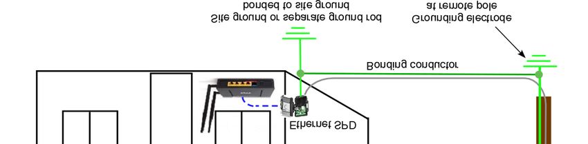
Figure 11
 Pole Mounted PoE Security Cameras

 7.0 Device Grounding

 Electronic devices, powered using a PoE powering device, mounted in a manner
 that exposes them to a lightning strike or the effects of a nearby lightning strike,
 should be installed with proper grounding to help mitigate the effects of a direct or
 near by lightning strike. These devices should be grounded to the site grounding
 system per chapter 8 of the NFPA 70® (8). In most cases this should be the local
 AC service ground or the intersystem bonding termination device.

 Equipment mounted on a pole separately from a building should have at least one
 grounding electrode placed at the base of the pole. This electrode should be
 bonded to the building grounding system with a bonding conductor sized per NFPA
 70® (8) Article 250. See Figure 17 in this document for details.

 Where the SPD is placed at a point greater than 20 conductor feet from the existing
 building ground, an additional grounding electrode should be placed at the SPD.
 The additional grounding electrode should be bonded to the existing ground with a
 minimum 6 AWG copper conductor. See Article 800 of the 2017 edition of the NFPA
 70® (8) for additional information. Grounding conductors should be as short and
 straight as possible. All bend radii should be a minimum of 8 inches with an
 inclusive angle of more than 90 degrees.

Copyright © Daniel G Ashton 2021
8.0 Surge Protective Devices (SPD’s)

 SPDs should be installed at both ends of any PoE circuit exposed to lightning. As
 explained in (7), if an SPD is only installed at one end of the exposed circuit during
 a lightning strike, there will be a voltage rise that is nearly equal to the maximum
 induced voltage, applied to the unprotected end of the circuit, once the SPD clamps.
 (See Figures 12 and 13) For this reason, SPDs should be installed as described in
 this document and as laid out in chapter 8 of NFPA 70® (8) and chapter 4 of NFPA
 780® (9)

 Cabling such as a twisted pair ethernet cable, should have an SPD installed at the
 external equipment and as close as practical to the point where the cable
 penetrates the structure’s exterior wall. The SPD should be listed by a nationally
 recognized test laboratory (NRTL) and rated for the appropriate data speed.

 Figure 12
 Results of a Single SDP

 Figure 13
 Results of Two SPD’s
Copyright © Daniel G Ashton 2021
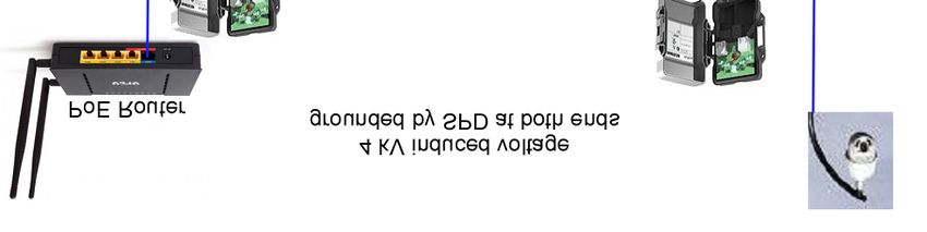
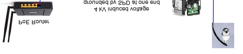
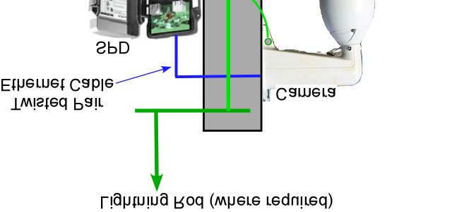
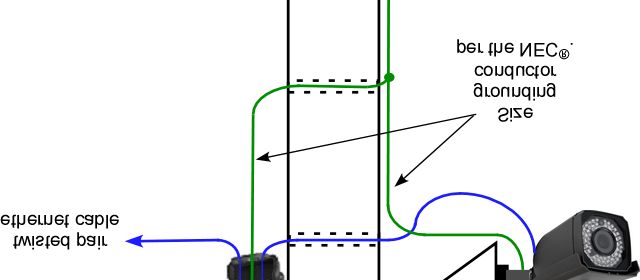
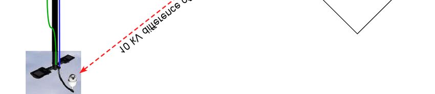
9.0 Recommended Lightning Protection for Externally Mounted Devices

 9.1 Security Cameras

 Cameras, installed in an outdoor environment, should be grounded to the site
 grounding electrode(s) or bonded to the intersystem bonding termination device.
 Twisted pair ethernet cables should have a listed SPD, rated for the appropriate
 data speed, installed at the camera (see Figure 19) and as close as practical to the
 point the cable enters the structure. See Figures 14 through 17

 For cameras mounted on a pole separate from a building, a single air terminal may
 be mounted on top of the pole above the camera(s) and grounded to the pole
 grounding electrode (per NFPA 780® (9) Annex J). See Figure 18

 Figure 14
 Long Ethernet Cable Exposure

Copyright © Daniel G Ashton 2021
Figure 15
 Short Ethernet Cable Exposure/ Pitched Roof

 Figure 16
 Short Ethernet Cable Exposure/ Flat Roof

Copyright © Daniel G Ashton 2021
Figure 17
 Pole Mounted Cameras

 Figure 18
 Pole Mounted Cameras With an LPS

Copyright © Daniel G Ashton 2021
Figure 19
 Pole mounted Camera with SPD
Copyright © Daniel G Ashton 2021
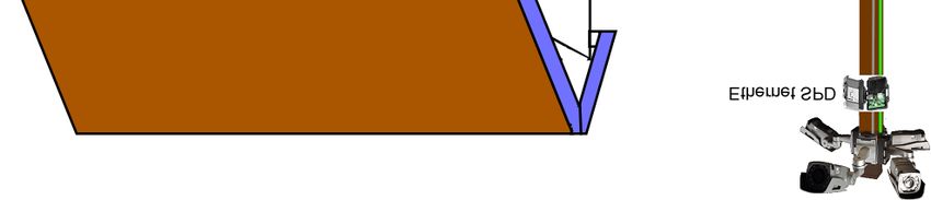
9.2 Ethernet (Fixed Wireless) Radio Systems

 PoE radio systems for Ethernet services have a remote radio head (RRH) placed on
 the exterior of the structure being served. These radios, when placed above the roof
 line of a structure without an LPS or placed above an LPS, are susceptible to
 damage from direct strikes. Proper grounding and the placement of SPDs should
 help limit the damage to these systems. See Figure 20

 The Ethernet cables may have long exposures on the structure’s exterior depending
 on where the RRH’s are installed. Under certain conditions, adding a single air
 terminal (lightning rod) above the RRH may add additional protection. See Figure
 21

 See Figure 22 for buildings with an existing LPS. For information regarding the
 installation of a lightning protection system, refer to NFPA 780® (9).

 Figure 20
 Ethernet Radio Grounding and SPD Installation

Copyright © Daniel G Ashton 2021
FIGURE 21
 Add Single Lightning Rod

Copyright © Daniel G Ashton 2021
Figure 22
 Existing or Added Lightning Protection System

 For structures with an LPS, the same rules for the zone of protection apply. Any
 PoE powered device should be installed in a manner that places it within the zone
 of protection. The LPS should be bonded to the local building ground and any
 device installed within 6 feet of an LPS conductor or air terminal should be bonded
 to the LPS system.

Copyright © Daniel G Ashton 2021
10.0 References

 (2) Dwelley, D. (2015), “A Quick Walk Around the Block with PoDL”

 (3) IEEE 802.3TM series on techniques for transmitting power over Ethernet cabling.

 (4) Martin, A. R. (2011a). “A new TIA standard for equipment installations with two
 or more separate grounds” ATIS PEG Conference 2011 (This Document is
 available from the Alliance for Telecommunications Industry Solutions (ATIS)
 ).

 (5) Martin, A. R. (2011b). “Lightning Damage to Equipment without a Metallic
 Connection to an External Communications Service” In Compliance Magazine,
 September 2011, pp 40-47.

 (6) Martin, A.R. (2016A), “Effects of Lightning on ICT Circuits: Induction and
 GCR”, In Compliance Magazine, April 2016, pp36-46.

 (7) Martin, A.R. (2016B), “Loop Currents Caused by Lightning-Induced
 Induction and GCR”, ATIS PEG Conference 2016 (This Document is
 available from the Alliance for Telecommunications Industry Solutions
 (ATIS) ).

 (8) Maytum, M.J. (2014), “Magnetically induced voltages and currents in
 Ethernet cables due to lightning strokes.”

 (9) NFPA 70®, National Electrical Code® (NEC®).

 (10) NFPA 780®, Standard for the Installation of Lightning Protection Systems.

 (11) Yseboodt, L. and Abramson, D. (2018), “Overview of 802.3bt - Power over
 Ethernet standard”.

Copyright © Daniel G Ashton 2021
You can also read