Using computer simulation in designing new products
←
→
Page content transcription
If your browser does not render page correctly, please read the page content below

Journal of Physics: Conference Series

PAPER • OPEN ACCESS

Using computer simulation in designing new products
To cite this article: A V Kramorov and A G Yanishevskaya 2021 J. Phys.: Conf. Ser. 1791 012101

View the article online for updates and enhancements.

                              This content was downloaded from IP address 46.4.80.155 on 11/03/2021 at 12:58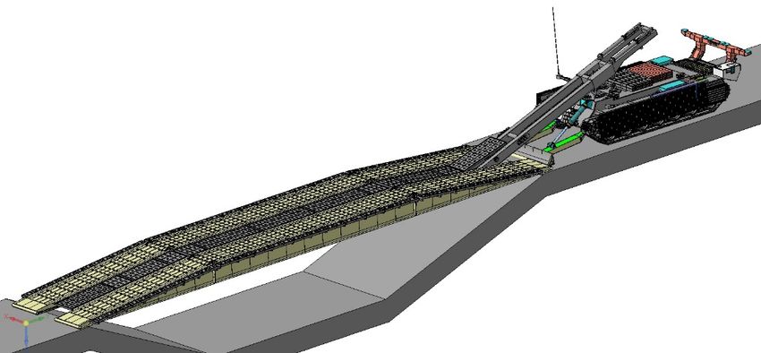
AMSD 2020                                                                                                       IOP Publishing
Journal of Physics: Conference Series                         1791 (2021) 012101          doi:10.1088/1742-6596/1791/1/012101

Using computer simulation in designing new products
                     A V Kramorov1 and A G Yanishevskaya2
                     1
                      Omsk Transport Engineering Plant, Omsk, Russia
                     2
                      Omsk State Technical University, 11 Mira ave., Omsk, 644050, Russia
                     E-mail: artem.kramorov@mail.ru
                     E-mail: anna-yanish@mail.ru

                     Abstract. Design of new products and mechanisms is continuous and complicated process.
                     The complexity of new products is explained by increased requirements for reliability and wide
                     functionality of new products for its competitiveness. At the same time, design time is reduced
                     by replacing natural tests with computational experiments and the widespread use of modern
                     computer-aided design systems (CAD systems). This article presents the design of the bridge
                     laying mechanism of tank bridge layer using modern CAD systems.

1. Introduction
In domestic and foreign combat manuals and regulations for engineering support of the battle, it is
emphasized that, depending on the prevailing situation in the main types of combat operations, the
subunits must carry out rapid attacks and marches [1]. In this case, the most important tasks are
deployment of new bridge crossings and restoration of destroyed ones by the enemy. To solve these
tasks, the tank bridges are used. Military application bridges were constructed several thousand years
ago. Their primary function was to allow warriors, arms and equipment to cross barriers – rivers,
ravines or other naturally and artificially made obstacles. After military operations these bridges
performed the functions of military and civil communications. Time passed and development of
military equipment and bridgebuilding created improved means of erecting bridge structures in the
shortest time period [2]. In world practice, successful experience has been accumulated in the creation
of tank bridgelayers for the deployment of bridges having length up to 25 m, with treadway not
exceeding 4 m (Figure 1) [3]. When the convoy of vehicles enters such bridges, as a rule, its speed
decreases in 2 - 4 times due to psychological and technical reasons. Such situation increases the
possibility of formation of vehicles’ clusters in front of the bridge, which creates conditions for the
destruction of all vehicles by the enemy.

                                                         Figure 1. Bridge
              Content from this work may be used under the terms of the Creative Commons Attribution 3.0 licence. Any further distribution
              of this work must maintain attribution to the author(s) and the title of the work, journal citation and DOI.
Published under licence by IOP Publishing Ltd                          1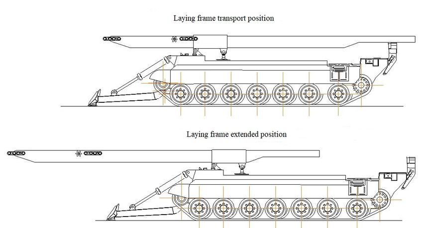
AMSD 2020                                                                                  IOP Publishing
Journal of Physics: Conference Series          1791 (2021) 012101    doi:10.1088/1742-6596/1791/1/012101

It is known that in the operational-tactical combat zone, the time of bridge crossing safe operation in
one location with 80 ... 90 % probability of not being hit will be 25 ... 30 minutes. Foreign and
domestic tactical manuals and regulations distinguish the bridge crossings as objects of priority defeat.
This is exacerbated by the extremely rapid development of reconnaissance assets and new types of
weapons in modern warfare. Increasing the efficiency of the use of tank bridgelayers through technical
development should be aimed at increasing the reliability during operation, increasing the mean time
between failures, minimizing the time for bridge deployment and retrieving, increasing the bridge
crossing capacity by increasing the width of the bridge at least 4.6 m, ensuring the safe and non-stop
vehicle passage on the bridge with a solid track-way [4].

2. Materials and research methods
One of the pressing problems in the bridge engineering is the development of rapidly deployable
single span bridges capable of being placed on a single vehicular mounting means. Such bridge
constructions may be used in instances where it is impossible to erect intermediate supports in a short
time period. The reason is short time allotted for laying a bridge on the one hand, and, in case of
availability of the intermediate supports on an obstacle, their big length, lack of information about
physical and mechanical properties of soil, very fast flow of rivers, complicated outline of a profile
and many more factors on the other hand [5]. According to modern requirements for tank bridgelayers,
it is necessary to overcome obstacles having width up to 26 m (the length of the bridge must be at least
27 m), and the width of the bridge track-way must be at least 4.6 m. Development of such bridge will
increase its weight, and the existing domestic tank bridge-laying vehicles are not able to install on
obstacles and remove from the obstacle bridges of increased weight, therefore, the development of a
new bridge-laying vehicle is required.
Under current conditions, the design of complex structures is impossible without the use of CAD,
which can reduce the development time due to 3D modeling, provide demonstration and possibility to
examine in detail the interaction of units and mechanisms while avoiding possible design errors.
The layout of the bridge on the obstacle is shown in Figure 2. In the transport position, the bridge is on
the bridge-laying vehicle in the folded state, after reaching the obstacle, the sections of the bridge are
opened, then the bridge is extended and lowered onto the ground.

                                        Figure 2. Bridge layout

                                                     2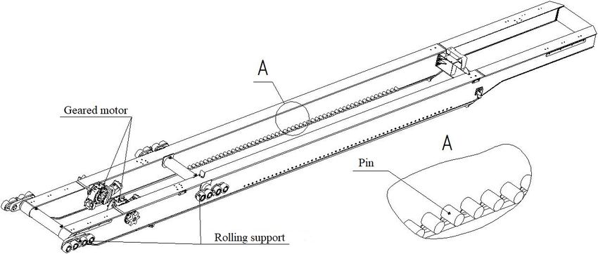
AMSD 2020                                                                                 IOP Publishing
Journal of Physics: Conference Series          1791 (2021) 012101   doi:10.1088/1742-6596/1791/1/012101

To lay the bridge with increased weight, one of the most important technical issues is to ensure
longitudinal stability against rolling-over of the bridge-laying vehicle when the bridge is installed on
the obstacle Figure 3.

                       Figure 3. Longitudinal stability without additional support

The weight of bridge-laying vehicle with bridge is limited by the vehicle cross-country ability
(specific ground pressure, loads on the support rollers of the vehicle running gear). When laying the
bridge with increased weight on an obstacle, longitudinal stability is not ensured. To increase the
longitudinal stability, the additional support is used (Figure 4). Creation of support with required
length L, allows not only to ensure longitudinal stability, but also to level the ground for the bridge
deployment or clear the road for the movement of a convey of vehicle.

                       Figure 4. Longitudinal stability without additional support

When designing a new bridge-laying vehicle for laying the bridge with increased weight, it is
necessary to develop bridge laying mechanism, which provides bridge extension and its laying on the
ground, using retractable laying frame, so that the end of the bridge could be behind the additional
support.

3. Design outputs
Inworkplaces, engineering design is supported by contemporary CAD tools capable of virtual
prototyping—a full-cycle process to explore the structure, function, and cost of a complete product on
the computer using modeling and simulation techniques before it is actually built [6].
For designing the bridge-laying vehicle it is required the CAD which provides the following:
- teamwork on the project;
- avoiding the fundamental mistakes at the earliest stages of design;
- demonstration of the future product and its assemblability checking;
- making the necessary calculations and optimization of the design without expensive field tests;
- change and modification of the project as soon as possible;
- preparation of effective marketing materials using of the 3D models;
- quick and qualitative execution of design documentation [7].
These requirements are met by the KOMPAS-3D system, which makes it possible to implement the
above provisions by including in the specified software product a set of libraries of ready-made
elements and circuits that meet the requirements of the machine-building industries, as well as provide
engineers with application design tools (element libraries, applied CAD systems) based on Compass [8].

                                                    3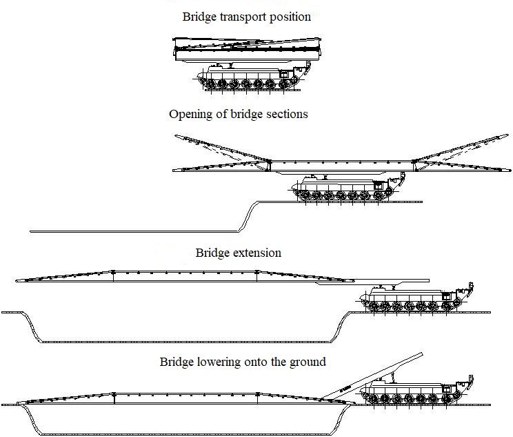
AMSD 2020                                                                                  IOP Publishing
Journal of Physics: Conference Series           1791 (2021) 012101   doi:10.1088/1742-6596/1791/1/012101

The 3D-modeling using in the design of the bridge-laying vehicle made it possible to organize the
interaction of designers from various departments involved in the development of separate units of
vehicle.
One of the main components of bridge-laying vehicle is the laying frame, on which heavy loads are
applied when the bridge is installed on the obstacle and it is removed from the obstacle. The wide
possibilities of the 3D-modeling made it possible to analyze possible options for a retractable laying
frame and choose the most rational option (Figure 5) meeting the specified requirements. In the
transport position, the bridge laying frame is within the dimensions of the bridgelayer, when the bridge
is installed on the obstacle, the frame moves forward, due to this, the bridge together with the laying
frame also moves forward and diverging from the bridgelayer support, lies on the original bank of the
obstacle.

                                 Figure 5. Retractable bridge laying frame

The laying frame consists of main frame and retractable frame.
The main frame (Figure 6) is installed on the vehicle hull and allows to install the retractable frame in
it. The main frame consists of welded frame and rolling supports, mounted on it, and two geared
motors for moving the retractable frame.

                                          Figure 6. Main frame

                                                     4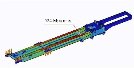
AMSD 2020                                                                                   IOP Publishing
Journal of Physics: Conference Series           1791 (2021) 012101    doi:10.1088/1742-6596/1791/1/012101

Retractable frame (Figure 7) is the assembly lever of bridge laying mechanism. It is welded structure
and consists of two longitudinal beams with rolling supports of bridge member mounted on them and
two geared motors for moving the bridge, in addition, pins for engagement with the sprockets of the
frame travelling mechanism are installed on the inner sheets of the beams.

                                        Figure 7. Retractable frame

To ensure the strength of the laying frame of the bridge laying mechanism, a detailed analysis of the
stress-strain state of structures is carried out to determine the most and least loaded points for optimal
solution with the lowest weight.
The creation of modern equipment at the design stage is not limited to its geometric modeling. It is
impossible to produce competitive products without a comprehensive engineering analysis of the
designed object. Developers around the world are working to ensure that their design solutions could
provide the static strength and rigidity, sufficient durability, stability and suitable dynamic
characteristics, while having minimum weight, minimum cost, minimum power consumption, etc. [9].
In science and technology, one constantly has to deal with the problem of calculating the systems that
have complex geometric configuration and irregular physical structure. Computers allow such
calculations to be performed using approximate numerical methods. The finite element method (FEM)
is one of them. The construction of a method using physical considerations and its name "finite
element method" is contained in an article written by engineers [10]. In recent decades, it has taken a
leading position and has been widely used [11]. To analyze the strength of the laying mechanism, the
Creo Simulate system was used, the use of which provides design engineers with powerful and
convenient tool that allows them to understand and analyze the real behavior of products under the
action of loads during their design [12]. The analysis of the designed laying mechanism showed the
possibility of providing strength using high-strength steel for some elements (Figure 8).
The creation of the 3-D model made it possible to develop in the shortest time the design
documentation in the KOMPAS-3D system that fully meets the requirements of Unified System for
Design Documentation.

               Figure 8. Calculation of the stress-strain state of bridge laying mechanism

                                                     5
AMSD 2020 IOP Publishing
Journal of Physics: Conference Series 1791 (2021) 012101 doi:10.1088/1742-6596/1791/1/012101
4. Conclusions
The use of CAD systems “KOMPAS-3D” and “Creo Simulate” made it possible in the shortest
possible time to develop the bridge-laying vehicle laying mechanism for deployment of 27 m bridge
with increased pass-through capacity with continuous roadway having 4.6 m width.
The necessary calculations were carried out, the interaction between the mating units and mechanisms
was checked, kinematic analysis of the bridge installation on the obstacle and taking from the obstacle
was carried out, design documentation was created in accordance with the requirements of Unified
System for Design Documentation.
Figure 9. Bridge installation on the obstacle
Reference
[1] Engineering Operations 2005 FM 5-100 (3-34) / USA 295 p
[2] Medzmariashvili E 2008 Transformable Multiple Use of Assault Bridge with 48 Meter Span
Bulletin of the georgian national academy of sciences 2 (4) pp 47-53
[3] Gromov A V, Surov O Y and Vladimirov S V 1984 Armament and equipment: handbook / by ed.
Gromova A V (Moscow: Voyenizdat) pp 232-235
[4] Noskov N N, Volkov A M and Zykova V K 2017 Methodology for assessing the effectiveness of
the use of tank bridges J. Bulletin of the Tula State University 9 (1) pp 487-493
[5] Sanikidze M, Tsignadze N, Medzmariashvili G 2017 Portable and rapidly deployable, single span
mechanized bridges for extreme situations Georgian technical university Works 3 (505) pp 101-
117
[6] Huang T, Kong C W, Guo H L, Baldwin A and Li H 2007 A virtual prototyping system for
simulating construction processes Automation in construction 16 (5) 576–585
[7] Three-dimensional modeling system KOMPAS-3D URL: https://ascon.ru/products/7/review/ (date
of the application 18.06.2020)
[8] Ryzhkov V A, Parinov M V and Koltsov A S 2015 Automation of building an assembly unit in the
KOMPAS 3D Solid modeling system Modern instrumental systems, information technology and
innovation 3 pp 411-416
[9] Magomedov A A and Alekhin A A 2010 Integrated finite element analysis in KOMPAS-3D
CAD/CAM/CAE Observer 8 (60) pp 1-4
[10] Turner M, Clough R, Martin H and Topp L 1956 Turner M. Stiffness and Deflection Analysis of
Complex Structures J. Aeronaut Sei. 23 (9) pp 805-823
[11] Rozin L A Finite element method 2000 Sorosovskiy educational journal 6 (2) pp 120-127
[12] Simulation and Analysis | Creo | PTC URL: https://www.ptc.com/ru/technologies/cad/simulation-
and-analysis (date of the application 14.06.2020)
6You can also read