EVIDENCE.com Dock Installation Manual
←
→
Page content transcription
If your browser does not render page correctly, please read the page content below
EVIDENCE.com Dock
Installation Manual

For use with:
AXON® body cameras and AXON flex™ cameras and controllers
          IMPORTANT SAFETY INSTRUCTIONS
          Read all warnings and instructions. Save these instructions.
The most up-to-date warnings and instructions are available at www.TASER.com.
MMU0054 Rev: B

                                                                                Page 1 of 22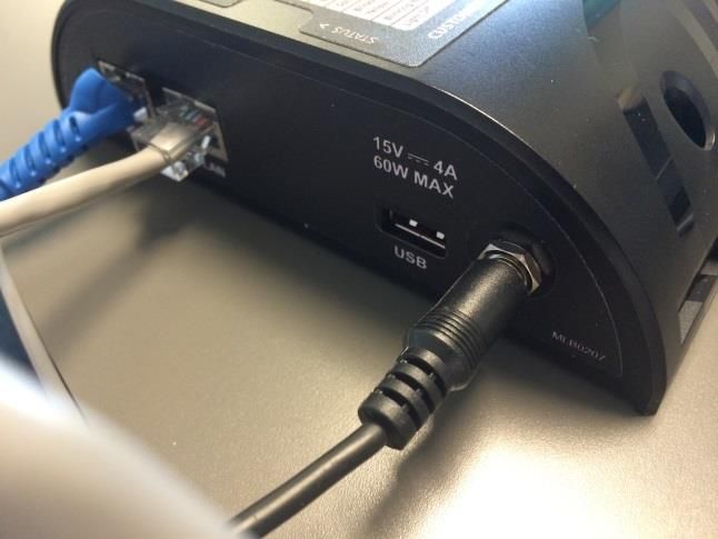
Contents
Chapter 1: Introduction to the EVIDENCE.com Dock ............................................................................................................. 3
    EVIDENCE.com Dock Components........................................................................................................................................... 3
    Additional Materials ....................................................................................................................................................................... 4
Chapter 2: Network Setup................................................................................................................................................................. 6
    Background ........................................................................................................................................................................................ 6
    Network Requirements ................................................................................................................................................................. 6
Chapter 3: EVIDENCE.com Dock Installation ............................................................................................................................. 8
    Introduction ....................................................................................................................................................................................... 8
Chapter 4: Wall Mounting an EVIDENCE.com Dock ............................................................................................................ 15
    Safety Instructions ........................................................................................................................................................................ 15
    Tools and Materials ..................................................................................................................................................................... 15
Chapter 5: Troubleshooting the EVIDENCE.com Dock ....................................................................................................... 19
    Status Lights ................................................................................................................................................................................... 20
Chapter 6: Network Troubleshooting ........................................................................................................................................ 21
    Status Page Errors ........................................................................................................................................................................ 21

                                                                                                                                                                                    Page 2 of 22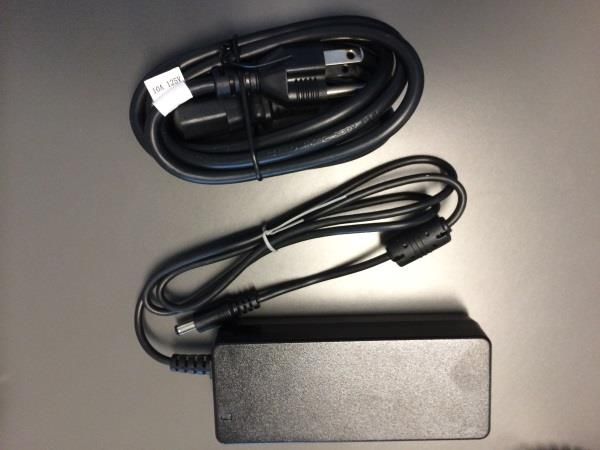
Chapter 1: Introduction to the EVIDENCE.com Dock

       The EVIDENCE.com Dock uploads videos from the AXON flex™ and AXON® body
       cameras to the EVIDENCE.com cloud computing website. While information is
       transferred securely to your organization’s account, the EVIDENCE.com Dock also
       recharges the batteries in the AXON system.

EVIDENCE.com Dock Components
       The EVIDENCE.com Dock has two major parts. One is the core (Figure 1), which
       connects to the Internet and transfers information to EVIDENCE.com. The other is the
       individual bay (Figure 2), which accepts the AXON hardware. The system is modular,
       and up to five individual bays can be connected to one core.

                                          Figure 1 Core
                                                                Accepts an AXON flex controller or
                                                                an AXON body camera

        Accepts an AXON flex camera

                                      Figure 2 Individual bay

       An additional bay, called the 6-bay (Figure 3), is available. The 6-bay accepts 6 AXON
       flex controllers (or 6 AXON body cameras) and 6 AXON flex cameras. It works with
       the same core as the individual bay.

                                                                                             Page 3 of 22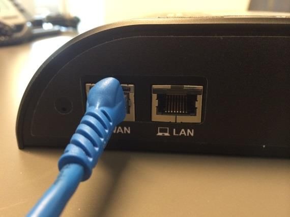
Figure 3 Core and 6-Bay

         A bridge adapter is used to attach the core to a bay, and to attach individual bays to
         each other. Figure 4 shows front and back views of a bridge adapter.

                                                    CAUTION

          Be careful when removing a bridge adapter from a bay, as damage may occur if the bridge
          adapter is removed unevenly from the bay. Bridge adapters must be pulled straight out
          and not angled when removed.

                          Figure 4 Bridge Adapter Front (left), Back (right)

Additional Materials
         The package containing the EVIDENCE.com Dock also contains 2 Ethernet cables
         (Figure 5) and an external power supply with an AC power cable (Figure 6).

                                                                                        Page 4 of 22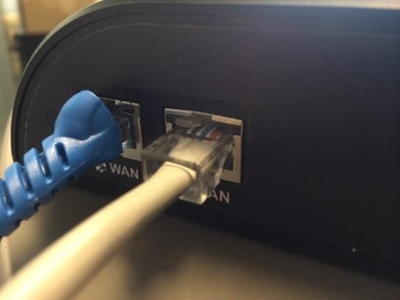
Figure 5 Ethernet Cables

Figure 6 Power Supply and AC Cable

                                     Page 5 of 22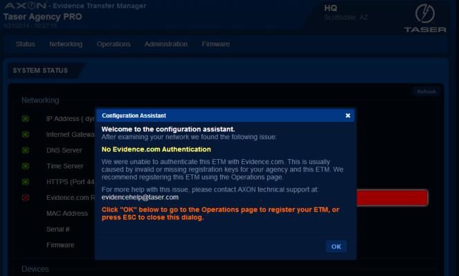
Chapter 2: Network Setup

Background
        AXON® on-officer camera systems capture video and audio recordings. When the
        AXON user(s) finish their shifts, the AXON system is docked into the EVIDENCE.com
        Dock. The EVIDENCE.com Dock uploads the content securely via 256-bit SSL to
        EVIDENCE.com. Using an agency account on EVIDENCE.com, AXON users can review
        the content, create clips, share evidence with other personnel in the organization,
        and download videos.

Network Requirements
        To get the EVIDENCE.com Dock up and running, you may need some assistance from
        your IT department.
        Although the EVIDENCE.com Dock has been hardened against external intrusion, it is
        STRONGLY recommended that the Dock be placed behind a standard firewall device.

                                               CAUTION

         DO NOT place the EVIDENCE.com Dock directly on the Internet. Doing so could make your
         system vulnerable.

        The EVIDENCE.com Dock and AXON devices do not require any incoming data ports
        for regular operation. All EVIDENCE.com Dock communications are outbound. All
        video and data files are transmitted securely using HTTPS and 256-bit AES
        encryption. For proper operation, the EVIDENCE.com Dock requires port 443 (TCP)
        opened for outgoing traffic to prod.evidence.com. This is used by the EVIDENCE.com
        Dock to send video and data files to EVIDENCE.com using the HTTPS protocol.
        If the EVIDENCE.com Dock is placed on a network that utilizes external DNS servers,
        then port 53 (UDP) must be opened for outgoing traffic to allow the EVIDENCE.com
        Dock to access those servers.
        The EVIDENCE.com Dock uses one of four methods to synchronize the clocks on the
        AXON devices:
        1.   HTTP over port 80 (TCP) to synchronize time from prod.evidence.com;
        2.   HTTP over port 80 (TCP) to synchronize time from google.com;
        3.   NTP over port 123 (UDP) to synchronize time from pool.ntp.org; or
        4.   NTP over port 123 (UDP) to synchronize time from a Network Time Server
             located on the default gateway assigned to the EVIDENCE.com Dock.
        The EVIDENCE.com Dock requires only one of the above methods to be available.
        Method #4 is the most secure, requiring no additional ports to be opened in a

                                                                                     Page 6 of 22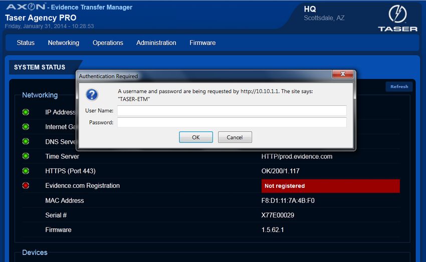
firewall. If one of the other methods is used to synchronize time, then the correct
port and destination must be opened for outgoing traffic in your firewall.
The AXON system does not currently support HTTP/HTTPS Proxies. If the
EVIDENCE.com Dock is placed on a network where a proxy is used to access web
sites, the IP assigned to the EVIDENCE.com Dock must be whitelisted. Depending on
the specific network setup, this may require a static or reserved DHCP IP.
If you have any questions on setup, call TASER Customer Service at 1-800-978-2737.

                                                                             Page 7 of 22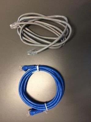
Chapter 3: EVIDENCE.com Dock Installation
Introduction
Installing your EVIDENCE.com Dock consists of several steps, to be followed in order.
Step 1: Accept the EVIDENCE.com Administrator Invitation
Ensure that you know your username, password, and agency domain name.
This email invitation will come from noreply@evidence.com.
If you do not accept the invitation, you will not be able to complete
EVIDENCE.com Dock setup.
Step 2: Device Placement
1. Take the EVIDENCE.com Dock out of the box and confirm that all pieces are
present.
2. Connect your core to all bays you plan to use (Figure 7).
Note: Do not attach more than 5 individual bays or 1 6-bay to 1 core.
Figure 7 Core and Individual Bay
CAUTION
Do not attach more than 5 individual bays to a core. The system will not provide
power to more than 5 individual bays. AXON cameras in any extra bays will not
upload any data to EVIDENCE.com and AXON devices in any extra bays will not be
recharged.
3. Place the connected EVIDENCE.com Dock on a flat surface, away from heat
sources and direct sunlight.
See “Wall Mounting an EVIDENCE.com Dock” on Page 20 for additional
information on utilizing the Wall Mount.
4. Place the Dock within reach of appropriate power and Ethernet connections.
Page 8 of 22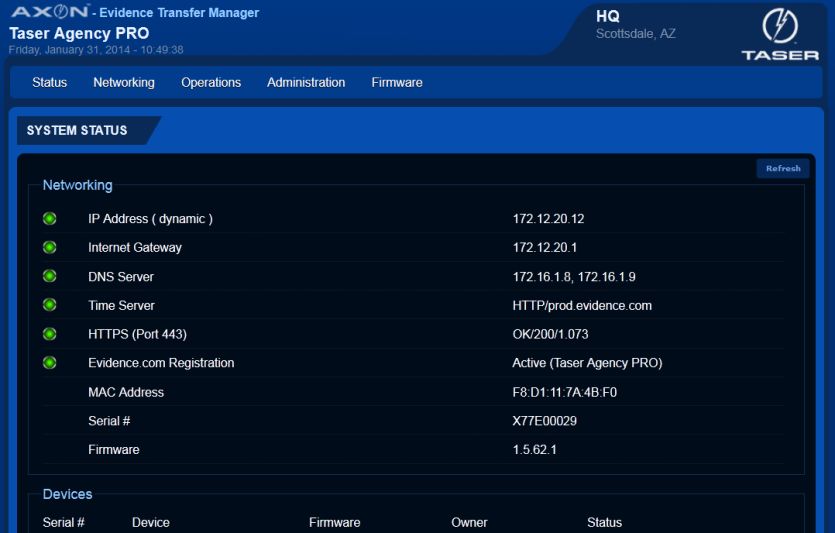
Step 3: Connect to Network
The back of the Evidence.com Dock has 2 ports for Ethernet cables, the WAN and
LAN ports (Figure 8).
Note: The USB port on the rear of the core is not currently functional. It is there for
future applications.
USB port
Reset button
Power port
WAN (to Internet) LAN (to computer)
Figure 8 Core Rear View
1. Plug one of the Ethernet cables into the WAN port. (Figure 9)
Note: The color of your Ethernet cables may be different from what is shown
below.
Figure 9 WAN Cable
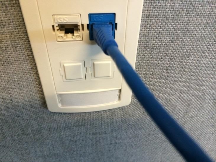
2. Plug the other end of this Ethernet cable into an active Internet port, which
connects to your agency network (Figure 10):
Page 9 of 22Figure 10 Network Connection
3. Plug the other Ethernet cable into the LAN port (Figure 11).
Figure 11 LAN Cable
4. Plug the other end of this Ethernet cable to your computer.
CAUTION
DO NOT connect the LAN port to the wall.
Step 4: Connect to Power
1. Connect the two segments of the power cord included with the EVIDENCE.com
Dock.
2. Plug the power cord into the EVIDENCE.com Dock (Figure 12).
Page 10 of 22Figure 12 Power Connection
3. Connect the other end of the power cord to a standard power outlet.
The green “POWER” LED on top of the core will light up when the Dock is
powered.
4. Give the Dock 2 minutes to fully start.
The green “STATUS” LED on top of the core will light up when the Dock has
started.
Step 5: Connect to the EVIDENCE.com Dock
1. Confirm that the computer connected to the EVIDENCE.com Dock does not have
wireless Internet turned on.
2. Confirm that the computer connected to the EVIDENCE.com Dock is not
connected to your network in any other way. Ensure that there is no wireless
connection enabled and no VPN (remote access) software active on your
computer.
3. Open a Web browser, such as Google Chrome or Mozilla Firefox.
Note: If you are using Internet Explorer, ensure that you are using version 8 or
greater.
4. In the URL box, type 10.10.1.1 and press Enter (Figure 13).
Figure 13 Web Browser
5. In the Configuration Assistant dialog box, click OK (Figure 14).
Page 11 of 22Figure 14 Configuration Assistant
Step 6: Device Configuration
Complete the information Authentication Required dialog box:
1. In the User Name box, type admin (Figure 15).
2. In the Password box, type admin.
3. Click OK.
Note: TASER strongly recommends that you change the password at this time.
Go to the Administration tab and enter your information, using the
existing username and password. In the Password Change section, type
the new password twice and click Save Changes.
CAUTION
Ensure that you remember the password. It cannot be reset.
Figure 15 Authentication Required
Step 7: Administrator Login
Page 12 of 221. In the Domain name box type your agency’s evidence.com domain name
(Figure 16).
Note: When typing your agency’s domain name, leave out .evidence.com. For
example, if your agency’s EVIDENCE.com website address is
gothampd.evidence.com, you would type gothampd.
2. Type the admin username and password that you previously created when you
first registered with EVIDENCE.com in the respective boxes.
3. Click Save Changes.
Figure 16 Create Your Login Credentials
Step 8: Registration
The system will then report that it is “Registering the EVIDENCE.com Dock,” then
“Generating Security Tokens,” and finally “Restarting the EVIDENCE.com Dock.”
• Allow up to 2 minutes for the system to restart.
Once the system is ready, the page will refresh and display the message ”The
ETM has already been registered with Evidence.com” (Figure 17).
Note: Do not click the Save Changes button. You are already registered when
this message is displayed. Go to Step 9: Confirm Registration.
Figure 17 Registration Message
Page 13 of 22Step 9: Confirm Registration
• Click Status on the top-left part of the screen.
There should be 6 green lights on the left side of the screen. This EVIDENCE.com
Dock is now registered (Figure 18).
Figure 18 System Status
Page 14 of 22Chapter 4: Wall Mounting an EVIDENCE.com Dock
Safety Instructions
Before mounting your EVIDENCE.com Dock:
1. Ensure that the area behind the wall where the EVIDENCE.com Dock will be
located is clear of obstructions to avoid damage to surroundings, pipes or
existing wiring.
2. Ensure that your cables meet all applicable building and fire codes. For in-wall
installation, most require UL-rated wire labeled CL2 or CL3.
Tools and Materials
Tools Materials
Cable-wire tester/locator EVIDENCE.com Dock Wall Mount Kit
Level
Pencil
Power drill and bits
Screwdriver
Stud finder
Tape Measure
Step 1: Preparation
1. Ensure that you have all necessary hardware and cables required to complete the
installation.
2. Read all of the manufacturer's installation instructions for both the
EVIDENCE.com Dock and the Wall Mount Bracket.
3. Decide if you will leave the cables showing or hide them in the wall behind your
EVIDENCE.com Dock.
Step 2: Attach the EVIDENCE.com Dock to the Wall Mount Bracket
1. Place your EVIDENCE.com Dock on the Wall Mount Bracket.
2. Align the holes of the core unit with the holes on the bracket.
3. Use the screws provided in the EVIDENCE.com Dock wall mount kit to attach and
mount the core portion of the Dock to the bracket.
4. Use the screws, washers and wing nuts to mount the opposite end bay portion to
the bracket.
Page 15 of 224.a Put the screws through the furthest set of mounting holes in the bay (making
sure the core and bays are securely mated together).
4.b As the screws come out the backside of the bracket, attach the washers and
add the wing nuts.
5. Confirm that the core and bay units are securely mated.
6. Finish tightening all of the screws.
Step 3: Identify EVIDENCE.com Dock Placement
Determine the best wall location for mounting the EVIDENCE.com Dock(s).
1. Look for a location away from heat sources and direct sunlight that does not
obstruct movement.
2. Choose a location close to an electrical outlet and a network outlet (Figure 10).
Measure the length of the EVIDENCE.com Dock’s power cord to be sure that it
will reach.
Step 4: Attach the Wall Mount Bracket to the Wall (Stud mount)
Your EVIDENCE.com Dock Wall Mount Kit comes with hardware for mounting the
bracket to a stud or mounting directly into drywall. If you are going to install the
bracket to drywall, go to Step 5: Attach the Wall Mount Bracket to the Wall (Drywall
mount).
Note: Use the longer screw for mounting the bracket into a stud.
1. Using a stud finder, mark the location of each stud’s center with a pencil.
1.a Use a nail to confirm a stud has been located.
Note: Depending on the wall construction, you may not be able to mount
both ends of the Wall Mount Bracket into the stud.
1.b Use the drywall anchors in the EVIDENCE.com Dock Wall Mount Kit for the
other mounting locations if needed.
2. Position the EVIDENCE.com Wall Mount Bracket on the wall and align the
mounting keyhole in the left side of the bracket with the center line of the stud.
2.a Use a level to ensure the bracket is level before marking the holes.
2.b Mark the center of the left side keyholes in the center of each wall stud.
2.c Using a power drill, drill a pilot hole smaller than the screw diameter.
2.d Install the screws into the stud until there is 1/8” [3.2 mm] of space between
the bottom of the screw head and the wall.
Page 16 of 22This will allow the bracket to be placed onto the screws and settle in the
keyhole (the holes in the bracket are shaped like keyholes to make it easier
to adjust the mount’s position on the wall).
2.e Repeat steps 2.a–2.d for the other side of the mount bracket.
2.f After the Wall Mount Bracket is positioned correctly, tighten all of the screws.
3. Go to Step 6: Connect the Cables.
Step 5: Attach the Wall Mount Bracket to the Wall (Drywall mount)
Your EVIDENCE.com Dock Wall Mount Kit comes with hardware for mounting the
bracket to a stud or mounting directly into the drywall. If you are installing the
bracket to a wall stud, go to Step 4: Attach the Wall Mount Bracket to the Wall (Stud
mount).
Note: Use the screw-in anchors and shorter screws for drywall installation.
1. Find the location where you want to mount the Wall Mount Bracket.
2. Locate the EVIDENCE.com Wall Mount Bracket on the wall.
2.a Use a level to ensure the bracket is level before marking the holes.
2.b Mark the center of the 4 keyholes on the wall.
2.c Remove the Wall Mount Bracket and screw in the drywall anchors in each
location.
2.d Screw in each of the screws until there is 1/8” (3.2 mm) of space between the
bottom of the screw head and the wall.
2.e This will allow the bracket to be placed onto the screws and settle in the
keyhole.
2.f After the Wall Mount Bracket is positioned correctly, secure all of the screws.
Step 6: Connect the Cables
1. There is space provided on the horizontal shelf to secure the power supply for
the EVIDENCE.com Dock.
1.a Position the power supply between the slots in the bracket and secure the
power supply to the bracket with the VELCRO strap.
1.b Route the barrel connector around the edge guard and plug the barrel
connector into the power jack on the Dock.
1.c You can secure the cable in position with the attached zip tie and the
associated slots in the bracket.
1.d Plug the power supply cable into a power strip or nearby AC outlet.
Page 17 of 222. Plug the CAT 5e (or better) cable from your agency’s network data jack into the
WAN port on the Dock.
You can secure the cable in position with the attached zip tie and the associated
slots in the bracket.
Page 18 of 22Chapter 5: Troubleshooting the EVIDENCE.com Dock
I cannot reach the status page
Ensure that Wi-Fi or any other Internet connection is disabled/disconnected on
your computer. If an Internet connection is enabled on your computer, it may
interfere with accessing the EVIDENCE.com status page.
Ensure that the computer you are connecting to the EVIDENCE.com Dock is not
set to use a static IP address.
Try another Ethernet cable connecting your computer to the EVIDENCE.com
Dock.
Ensure that the EVIDENCE.com Dock is plugged into an active power outlet.
Try accessing http://10.10.1.1 from a different browser or computer, if possible.
The status page is giving an error
If you receive an error that indicates anything besides completing the
EVIDENCE.com Authentication, please refer to the Network Requirements section
in this manual to confirm network requirements are met.
I am asked for a username and password when navigating to 10.10.1.1
The username for the EVIDENCE.com Dock is admin and the password is admin.
This will be a pop up box after you click OK on the configuration assistant.
I don’t know my Agency Domain or Username and Password
You can find your agency domain by going to http://prod.evidence.com and
typing in your email address. It will direct you to your organization’s
EVIDENCE.com account, thus providing your agency domain name.
For example, “YourAgencyPD.Evidence.com”
You must be an EVIDENCE.com Admin in order to register the EVIDENCE.com
Dock. Your username and password will be the same login credentials that you
use to login to your EVIDENCE.com account.
Page 19 of 22Status Lights
The core has a power LED to indicate the core is receiving power and a status LED to
indicate that the core’s software is running.
Power LED Status LED
Figure 19 Function LEDs
The power LED will be on when the bay is plugged into power. The power LED will be
off when the bay is not plugged into power.
The status LED may be green or red, solid or blinking, depending on the
EVIDENCE.com Dock’s system status.
System Status Status LED Indication
System running Solid green
System reset Solid red
Bay(s) reset Blinking green
Page 20 of 22Chapter 6: Network Troubleshooting
Status Page Errors
This section lists error messages and corrective actions.
We were unable to obtain an IP address from your DHCP server
Possible Issue Troubleshooting Steps
Internet port you are using is not active. Attempt to use a different internet port, or verify
that the current port is active.
Ethernet cable from WAN to internet port is Use a different Ethernet cable.
malfunctioning.
Agency network only accepts devices with static IP You must enter a static IP address, provided by
addresses. your IT department. For this, click on the
networking tab and fill in the required fields.
We were unable to locate a DNS server
Possible Issue Troubleshooting Steps
Port 53 is blocked. Confirm that Port 53 is not being restricted by
your firewall.
DNS Server address(es) entered incorrectly – This Return to the networking tab and verify that the
applies only when using Static IP configuration. DNS Server address information has been entered
correctly.
We were unable to communicate with a network time server
Possible Issue Troubleshooting Steps
Port 80 or Port 123 are blocked. Confirm that Port 80 and Port 123 are not being
restricted by your firewall.
We were unable to communicate over a secure (HTTPS) channel
Possible Issue Troubleshooting Steps
Port 443 is blocked. Confirm that Port 443 is not being restricted by
your firewall.
Page 21 of 22We were unable to contact your network’s default gateway
Possible Issue Troubleshooting Steps
Static IP address entered incorrectly. – This applies Return to the networking tab and confirm that the
only when using Static IP configuration. static IP address has been entered correctly.
Chrome is a trademark of Google Inc. Firefox is a trademark of the Mozilla Foundation. VELCRO is a trademark of Velcro Industries
B.V.
AXON flex, EVIDENCE.C©M, and ® are trademarks of TASER International, Inc., and AXON, TASER, and © are registered
trademarks of TASER International, Inc., registered in the U.S. All rights reserved. © 2014 TASER International, Inc.
Page 22 of 22You can also read