RECOMMENDED STANDARDS INSTALLATION WOODBURNING STOVES - for the of - Prepared By Office of State Fire Marshal 52 State House Station Augusta, ME 04333
←
→
Page content transcription
If your browser does not render page correctly, please read the page content below
RECOMMENDED STANDARDS
           for the
       INSTALLATION
             of
    WOODBURNING STOVES

                               Prepared By

Office of State Fire Marshal             Maine Office of Energy Resources
52 State House Station                   55 Capital Street
Augusta, ME 04333                        Augusta, ME 04330
RECOMMENDED STANDARDS FOR THE INSTALLATION
OF WOOD BURNING STOVES
This guide has been prepared to inform the people of the State of Maine of the recommended
standards for the installation of wood burning stoves. These standards have been approved by the Office
of State Fire Marshal in accordance with the National Fire Protection Association’s standards.
These standards cover all wood burning appliances with the exception of on-site constructed masonry
stoves and fireplaces; stoves with water jackets or coils; and wood fueled central heating systems
utilizing pipes, ducts, or similar distribution systems. Stoves for use in mobile homes should be
specifically listed for such use. All listed wood burning stoves should be installed according to the
manufacturers’ recommendations.
DEFINITIONS
APPROVED: Acceptable to the authority DRAFT: The natural force which conducts
having jurisdiction. smoke, hot air, and other gases to the outside
ASBESTOS MILLBOARD: A soft atmosphere.
insulating board made with compressed FIRE RESISTANT INSULATING BOARD:
asbestos fibers capable of being cut with knife Listed or approved materials suitable for
or hand saw. protecting combustible surfaces.
CHIMNEY: A vertical shaft enclosing one or FLUE: A tube, pipe, or shaft for passage of
more flues for conveying smoke, hot air, and smoke, hot air, gas, etc., as in a chimney.
other gases to the outside atmosphere. FLUE COLLAR: That portion of an appliance
CHIMNEY CONNECTION: The conduit designed for attachment to the chimney connector.
connecting the wood stove with the vertical FLUE LINER: A material which resists high
flue (generally stovepipe). temperatures and is designed specifically for lining
CIRCULATING STOVE: A wood burning chimneys or connectors.
appliance surrounded by an outer jacket with LISTED: Equipment or materials which meet
openings at the top and bottom so that room nationally recognized standards or tests which
air passes between the stove and the jacket. determine suitability of usage in a specified
COMBUSTIBLE WALL: Any wall section manner.
that has the potential to burn. Only solid RADIANT STOVE: Any wood burning appliance
masonry or corrugated steel walls are con- not designed as a circulating stove.
sidered non-combustible. Merely covering a THIMBLE: Liner for the passageway where the
wood studded wall with a non-combustible chimney connector enters the chimney flue.
material does not constitute a non-combustible WOOD BURNING APPLIANCE: Any free-
wall. standing unit which utilizes wood as a fuel to
COOK STOVE: A wood burning stove used produce heat. This includes stoves installed into
for cooking which includes an oven and surface fireplace openings.
heating areas.
1TABLE OF CONTENTS
I. Clearances from wood burning stoves
a. To walls and ceilings
b. To floors
II. Chimney connectors
a. Clearances from connectors
b. Installation
III. Chimneys
a. Chimney draft
b. Multiple connections
c. Listed pre-fabricated metal chimneys
IV. Organizations governing the installation of wood burning equipment
2I. CLEARANCES FROM WOOD BURNING STOVES
Stoves must be provided with adequate clearances from combustible materials.
The minimum clearances needed for safety are specified in National Fire
Protection Association Standard # 211, Chimneys, Fireplaces, Vents and
Solid Fuel Burning Appliances, 2003 Edition.
a. Clearances to Walls and Ceilings
Clearances indicated in Table 1 (below) are the minimum clearances
from wood burning stoves to unprotected combustible wall and ceiling
surfaces.
TABLE 1
Minimum Clearances from Wood Burning Stoves to
Combustible Surfaces with No Added Protection
Cookstove Cookstove Stovepipe Listed
Radiant Circulating Clay lined Firepot Unlined Firepot Stoves
Ceiling 36” 36” 30” 30” 18”
Install
According to
Front 36” 24” 18” Manufacturers
Firing side 24” Firing side 36” Recommendations
Side 36” 12” Opposite side 18” Opposite side 18” 18”
Rear 36” 12” 24” 36” 18”
NOTE
Stoves may be installed with clearances less than those specified in Table 1 provided
the combustible material is protected as described in Table 2 or Figure 1.
3TABLE 2
Minimum Clearances from Wood Burning Stoves with Specified Forms of Protection
( See Footnotes )
Where the required clearance with no
protection is 36 in. the clearances below
Clearance reduction applied to and covering all Maximum allowable the minimum allowable clearances. For
combustible surfaces within the distance specified reduction in clearance (%) other required clearances with no protection,
as required clearance with no protection calculate minimum allowable clearances from
maximum allowable reduction.
As Wall Protector As Ceiling Protector
As Wall As Ceiling inches inches
Protector Protector
(%) (%)
(a) 3 1/2 in. thick masonry wall without 33 - 24 -
ventilated air space
(b) ½ in. thick noncombustible insulation 50 33 18 24
board over 1-in. glass fiber or mineral wool
batts without ventilated air space
(c) 0.024-in., 24 gauge sheet metal over 1-in. glass 66 50 12 18
fiber or mineral wool batts reinforced with wire
or equivalent, on rear fact with ventilated air
space
(d) 3 ½ in. thick masonry wall with ventilated air 66 - 12 -
space
(e) 0.024-in., 24 gauge sheet metal with ventilated 66 50 12 18
air space
(f) ½ in. thick noncombustible insulation board 66 50 12 18
with ventilated air space
(g) 0.024-in., 24 gauge sheet metal with ventilated 66 50 12 18
air space over 0.024-in. 24 gauge sheet metal
with ventilated air space
(h) 1-in. glass fiber or mineral wool batts sandwiched 66 50 12 18
between two sheets 0.024-in., 24 gauge metal with
ventilated air space
Table 2 Guidelines and Details
continued on next page:
4Table 2 Guidelines and Details
Notes:
1. Spacers and ties shall be of noncombustible material. No spacers or ties shall be
directly behind appliance or conductor.
2. With all clearance reduction systems using a ventilated air space, adequate air
circulation shall be provided as described in section 9-6.2.4 of NFPA # 211. There
shall be a least 1 in. between the clearance reduction system and combustible walls
and ceilings for clearance reduction systems using a ventilated air space.
3. Mineral wool batts (blanket or board) shall have a minimum density of 8 lb/ft³ and
have a minimum melting point of 1500˚F (816ºC).
4. Insulation material used as part of clearance reduction system shall have a thermal
conductivity of 1.0 (Btu-in.)/(ft²-hr-ºF) or less. Insulation board shall be formed of
noncombustible material.
5. If a single-wall connector passes through a masonry wall used as a wall shield, there
shall be at least ½ in. (13mm) of open, ventilated air space between the connector and
the masonry.
6. There shall be at least 1 in. (25.4 mm) between the appliance and the protector. In no
case shall the clearance between the appliance and the wall surface be reduced below
that allowed in this table.
7. Clearances in front of the loading door or ash removal door, or both, of the appliance
shall not be reduced from those in Section 9-5, NFPA 211.
8. All clearances and thickness are minimums; larger clearances and thickness shall
be permitted.
9. To calculate the minimum allowable clearance, the following formula can be used:
C r = C n x [1 – (R/100]. C r is the minimum allowable clearance, C n is the
required clearance with no protection, and R is the maximum allowable reduction in
clearance.
10. Refer to Figures 9-6.2.1(e) and 9-6.2.1 (f), NFPA 211, for other reduced clearances
using materials found in (a) through (h) of this table.
5"A" equals the required "B" equals the
clearance with no reduced clearance
protection as specified permitted in
in Table 1. accordance with
Table 2. The
protection, applied to
the construction using
combustible material,
should extend far
enough in each
direction to make “C”
equal to “A”.
b. Clearances To Floors
General Requirements
Residential-type solid fuel-burning appliances that are tested and listed
by a recognized testing laboratory for installation on floors constructed of
combustible materials shall be placed on floors in accordance with the
requirements of the listing and conditions of approval. Such appliances that
are not listed by a recognized testing laboratory shall be provided with floor
protection in accordance with the provisions of 9-5.1.2 or 9-5.1.3 of NFPA
# 21 1.
Exception: Residential-type solid fuel-burning appliances shall be
permitted to be placed without floor protection in any one of the following
manners:
(a) On concrete bases adequately supported on compacted soil; crushed Rock, or
gravel
(b) On concrete slabs or masonry arches that do not have combustible materials
attached to the underside.
(c) On approved assemblies constructed of only noncombustible materials and
having a fire resistance rating of not less than 2 hours, with floors constructed
of noncombustible material
(d) On properly stabilized ground that can support the load of the Appliance
Any floor assembly, slab, or arch shall extend not less than 18 in. (457
mm) beyond the appliance on all sides.
See Table Below for Standard Floor Clearances:
6FLOOR CLEARANCES
FOR LISTED AND UNLISTED APPLIANCES
FLOOR CLEARANCES
Length of Stove Leg Floor Clearance and Protection
Less than 2 inches Fire resistant floor
2 – 6 inches Combustible floor protection by
4 inches of hollow masonry, laid
to provide circulation through the
masonry layer, covered by
24-guage sheet metal.
Over 6 inches Combustible floor protected by
2 inch thick masonry, placed over
a sheet of 24-gauge sheet metal.
• Listed fire-resistant insulating board can be installed according to the
manufacturer’s recommendations.
7II. CHIMNEY CONNECTORS
A chimney connector links a stove to the chimney flue. Chimney connectors
should be made from steel of minimum 24 gage thickness. Lower gage numbers
indicate thicker stovepipe.
a. Clearances from Connectors
The clearance from a chimney connector to a combustible material
should be not less than three times the diameter of the connector.
Where the combustible material is protected, the clearance may be
reduced to that indicated in Figure 1.
There are three methods for passing a chimney connector through a
combustible wall. Figures 2, 3, & 4 illustrate these methods. In Figure 2
sheet metal or metal lathe and plaster finish may be used. When installing
as illustrated in Figures 2 & 3, the distance from the connector to
combustible materials must be equal to three times the diameter of the
connector.
FIGURE 2 FIGURE 3
8Try to avoid passing a connector pipe through an interior wall. If this
must be done, use a ventilating thimble (See Figure 4). The thimble
diameter must be at least 12 inches larger than that of the stovepipe, thus
giving at least 6 inches of metal-lined, ventilated clearance. If you do not
use a thimble, the clearance must be three times the pipe diameter.
A 6 inch pipe would need a 42 inch diameter hole cut through a
combustible wall.
FIGURE 4
Listed solid fuel pre-fabricated metal chimneys can also be used to pass through
a combustible wall when installed according to manufacturers’ recommendations.
9b. Connector Pipe Installation
* Keep the connector pipe as short as possible. It should be no longer
than 75% of the vertical chimney height above the thimble where the
connector pipe enters the chimney.
* The stovepipe should be straight as well as short. Use no more than
two right-angle bends in the stovepipe installation. Additional bends
cause soot and creosote to collect in the stovepipe or chimney, block
flue gas flow, and increase the danger of fire.
* The connector pipe’s horizontal runs should rise ¼” for each foot of
pipe, with the highest point being at the thimble.
* When joining the pipe, overlap the joints at least two inches, with the
crimped end pointing down to prevent creosote drips or leaks. Secure
each joint with three sheet metal screws. A fireproof sealant may be
used in addition.
* All connector pipe joints should fit snugly, including connections with
the stove and thimble. The connector pipe must not stick into the
chimney flue itself because this would hamper the draft.
* Connector pipe should not pass through ceilings. Factory built,
listed, all-flue chimneys should be utilized when passing through
ceilings. Follow manufacturers’ installation instructions for these
chimneys.
* Connector pipe should not pass through closets. A closet fire could
smolder and spread undiscovered.
III. CHIMNEYS
The condition of a chimney should always be carefully evaluated before
considering the installation of a wood-burning appliance. Beware of cracks,
deteriorated mortar, and unsealed openings in any chimney before attaching a
wood burning unit to it.
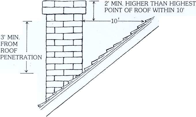
a. Chimney Draft
For sufficient draft a chimney should extend at least two feet higher than
any portion of the building within ten feet horizontally from it
(See Figure 5). The flue area should not be smaller than the largest
connector pipe plus 50% of the additional area of a second connector
entering the same flue.
10FIGURE 5
b. Multiple Connections
More than one wood burning appliance should not be connected to a
common flue. A chimney connector should not be connected to a flue
serving a fireplace or an oil furnace. They should have their own
individual flues.
One reason for this is that the sparks can enter the house through a
fireplace opening serving a woodstove elsewhere along the line. Both a
fireplace opening and an oil furnace’s barometric damper will furnish
large quantities of air to their flues. In the event of a chimney fire, this
will hamper any attempts to extinguish the fire by restricting airflow to the
flue. Using a wood-burning stove on a flue serving an oil furnace may
also reduce the efficiency of the oil furnace, due to the change in draft
characteristics of the flue. Multiple connections sometimes result in
insufficient draft. If two or more stoves are connected to the same
chimney flue, despite the recommendations against doing so, the
connectors must enter the chimney at different elevations.
11c. Listed Solid Fuel Pre-Fabricated Metal Chimneys
The use of pre-fabricated metal chimneys listed for installation with solid
fuel heaters (not furnaces) are within the guidelines of the State Standard.
Care should be taken, however, with the use of such chimneys to avoid
creosote accumulation and the associated potential danger of a chimney
fire. Air-controlled wood burning appliances should be operated in
accordance with manufacturers’ instructions to reduce the potential for
creosote build up. Pre-fabricated metal chimneys can break down under
the intense heat of a chimney fire, resulting in possible structural fire
damage. They should always be installed in accordance with the
manufacturers’ recommendations.
IV. ORGANIZATIONS GOVERNING THE INSTALLATION OF WOOD
BURNING EQUIPMENT
Certain Maine communities have ordinances governing the installation of wood
burning equipment. Always check with your local Fire Department or Building
Inspector before attempting installation. It is also important to consult with your
insurance company regarding any restrictions they may have on wood burning
appliance installation. All installations in public buildings must meet standards
set by the Office of State Fire Marshal.
The wood burning appliances listed below are not covered by this recommended
standard. For information on their installation, refer to the appropriate agency.
When Installing: Consult With:
Site Built Masonry Flues and Fireplaces Office of State Fire Marshal
Wood Fueled Furnaces or Boilers Oil and Solid Fuel Burner
Technicians Licensing Board
Wood Burning Units with Water Jackets Plumbing Code Enforcement
or Coils Officers
Listed Wood Fueled Mobile Home Heaters State Manufactured Housing Board
or Office of State Fire Marshal
Listed Wood Burning Stoves The manufacturers’ installation
recommendations
12You can also read