NEUTRONICS ANALYSIS OF VVER-1000 CORE USING AT-FCM FUEL
←
→
Page content transcription
If your browser does not render page correctly, please read the page content below
EPJ Web of Conferences 247, 02005 (2021)                                                               https://doi.org/10.1051/epjconf/202124702005
PHYSOR2020

           NEUTRONICS ANALYSIS OF VVER-1000 CORE USING AT-FCM FUEL

                                           Mahmood Ahmad Ghazanfar1*, Wang Kan1
                                                             1
                                              Tsinghua University
             Department of Engineering Physics, New LiuQing Building, Haidian District, Beijing P.R.
                                                   CHINA

                              jiangf16@mails.tsinghua.edu.cn, wangkan@mail.tsinghua.edu.cn

                                                                   ABSTRACT

                 Using the Fully Ceramic Microencapsulated (FCM) fuel in light water reactors has multiple
                 advantages, as it is accident tolerant because of; no hydrogen generation due to the cladding
                 interaction with steam at high temperature, better retention of fission fragments and
                 proliferation resistant due to very small production of transuranic elements during the burnup
                 as compared to the standard UO2 fuel. In this study neutronics analysis of AT-FCM fuel
                 consisting of TRISO particles embedded in SiC matrix is performed for replacement in
                 existing VVER-1000 reactors. Standard VVER-1000 fuel assembly is transformed to Accident
                 Tolerant Fully Ceramic Microencapsulated (AT-FCM) fuel assembly based on hydraulic
                 diameter of the VVER-1000 assembly, the number of fuel pins are decreased with increased
                 diameter and enrichment to conserve the initial fissile loading in AT-FCM assembly. Fuel
                 centerline temperature of the AT-FCM assembly is found to be lower than the reference UO2
                 fuel assembly at the same total power produced because of the much higher thermal
                 conductivity. FCM-TRISO fuel assembly namely Array 15 with 169 pins is proposed and
                 analyzed. Pin cell, assembly level and full core calculations have been performed with
                 SERPENT code using implicit and explicit models. VVER-1000 full core is modelled using
                 the transformed FCM assembly. The embedded TRISO particles in a SiC matrix and the use
                 of FeCrAl cladding turns out to be the perfect case for accident tolerance. High burnup of AT-
                 FCM core in terms of MWd/kgHM for the same number of EFPDs is observed as compared
                 to reference UO2 core due to the small breeding of transuranic elements Pu-239, Pu-240 and
                 Pu-241. Appreciable quantity of the power is produced due to the fission of transuranic
                 elements in reference UO2 assembly so the burnup in MWd/kgHM remains smaller than the
                 AT-FCM fuel. Comparatively more softening of spectrum is found in AT-FCM fuel cells and
                 assemblies towards the middle of the cycle (MOC) and End of the Cycle (EOC), this softening
                 of spectrum tends to increase the rate of U-235 depletion. Very small quantities of plutonium
                 isotopes are produced in AT-FCM as compared to the reference UO2 assembly because of small
                 loading of U-238 at the BOC. The neutronics performance of AT-FCM core with burnable
                 poison consisting of Gd2O3 and Er2O3 turn out to be better than reference UO2 assembly as it
                 exhibits smooth burnup. Fuel Temperature Coefficient (FTC) and Moderator Temperature
                 Coefficient (MTC) of the AT-FCM assembly is negative for most part of the cycle however,
                 towards the end of cycle it becomes less negative due to small quantities of resonance
                 absorbers, softening of thermal flux and increased rate of fission absorption in UO2.

         KEYWORDS: Fully Ceramic Microencapsulated (FCM) fuel; SERPENT; TRISO particles, VVER-1000;

  © The Authors, published by EDP Sciences. This is an open access article distributed under the terms of the Creative Commons Attribution License 4.0
  (http://creativecommons.org/licenses/by/4.0/).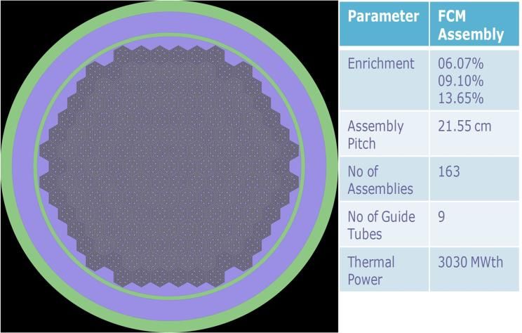
EPJ Web of Conferences 247, 02005 (2021)                                              https://doi.org/10.1051/epjconf/202124702005
PHYSOR2020

                                                   1. INTRODUCTION

         The idea of using FCM-TRISO fuel in LWRs is under consideration since the severe accident of Fukushima
         Daiichi power plants because of its proven performance in High Temperature Gas Cooled Reactors
         (HTGRs). It has multiple advantages such as better fission fragments retention, accident tolerant due to the
         use of innovative claddings, which does not interact with steam at high temperatures and proliferation
         resistance because of very small production transuranic elements. Research and development work is in
         progress to study the possible use of TRISO fuel in PWR environment [1] but almost no research work has
         been done on this fuel to be used in VVER type reactors. Many options are available for fuel kernel of the
         TRISO particles but lately most of the research work has been focused on Uranium Carbide (UC) and
         Uranium Nitride (UN). Similarly relatively new cladding concepts such as ferritic steel FeCrAl, Silicon
         Carbide SiC and alloys of zirconium have been studied; each one has its own advantages and disadvantages
         [2]. This neutronics analysis is performed using SERPENT code with explicit and implicit methods.
         Depletion analysis, energy spectrum analysis, transuranic elements breeding and reactivity coefficients of
         temperature are simulated considering the double heterogeneity of FCM-TRISO fuel.
         The section two of this paper is about the Methods and materials while in section three the results of
         simulations have been discussed in detail. The conclusion of the results and future work is presented in
         section four.

                                            2. METHOD AND MATERIALS

         The standard assembly of VVER-1000 reactor, containing 331 pins in hexagonal geometry is taken as a
         reference assembly for this neutronics analysis. Reference assembly is transformed into accident tolerant
         Fully Ceramic Microencapsulated fuel (FCM-TRISO) assembly in two aspects i.e geometric transformation
         and enrichment transformation. The basic requirement of fuel centerline temperature in FCM assembly is
         also a constraint for this transformation. An assembly with 169 pins and FCM-TRISO fuel is proposed for
         assembly level calculations and then core design for VVER-1000 reactor. Fuel pin diameter of the FCM
         assembly is increased considering the much higher thermal conductivity of TRISO fuel embedded in SiC
         matrix [3]. The detailed transformation of reference assembly to FCM assembly is discussed in detail in the
         following section 2.2. These transformed FCM assemblies are then used to design VVER-1000 core and
         neutronics analysis is performed.

         2.1.     Tools and Methodology

         Monte Carlo code SERPENT-1.1.19 [4] is used for this neutronics analysis. This code is capable of building
         complex combinatorial geometry and double heterogeneity of the TRISO fuel. The TRISO particles
         embedded in SiC are packed in fuel pin using implicit and explicit mehods. Burnup analysis of the FCM-
         TRISO assembly is compared with the standard UO2 fuel assembly, spectrum analysis, relative power
         distribution, material inventories and burnup analysis with burnable absorbers has been performed in this
         study. ENDBF-VII.0 cross section libraries and periodic boundary conditions are applied in this analysis.

         2.2. Transformation of Reference UO2 Assembly to FCM Assembly

         A standard VVER-1000 assembly consists of 331 pins, among them 312 are fuel pins and 19 guide tubes
         for control assembly and instrumentation tube. The first step of the transformation is to calculate the fuel
         rod diameter and the pitch of fuel pins; this is determined by taking the pitch and hydraulic diameter of the
         reference assembly as constant. For FCM assembly 169 pins are fixed in hexagonal geometry, fuel rod
         diameter and other parameters of reference and FCM assemblies are presented in Table I.

                                                              2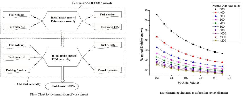
EPJ Web of Conferences 247, 02005 (2021)                                                https://doi.org/10.1051/epjconf/202124702005
PHYSOR2020

                                      Table I. Description of the Assembly parameters.

                                  Parameters                Reference Assembly         FCM Assembly
                     Fuel pellet radius                         0.3917 cm                0.6461 cm
                     Fuel material/matrix                             UO2                   UC/SiC
                     Packing fraction                                  –                      35%
                     Enrichment                                      4.2%                   15.97%
                     Heavy metal loading/FA                    486.748 kg                  128.298kg
                     HM% age of reference                           (100.0%)                (26.35%)
                     Initial fissile loading/FA                  20.43kg                     20.43kg
                     Density of fuel                           10.40 g/cm3                 12.95 g/cm3
                     Helium gap thickness                       0.0085 cm                   0.0085 cm
                     Clad thickness                              0.069 cm                   0.057 cm
                     No. of fuel rods                               312                        160
                     Fuel rod radii (outer)                     0.4572 cm                   0.7116 cm
                     No. of guide tubes                              19                         9
                     Guide tube radii (outer/inner)         0.630 cm/0.550 cm        0.8613 cm//0.8043 cm
                     Helium density                           0.00222 g/cm3              0.00222 g/cm3
                     Density of clad material (FeCrAl)               –                     7.25 g/cm3
                     Density of moderator (H2O)               0.72701 g/cm3              0.72701 g/cm3
                     Fuel temperature (ave)                       990.0 K                    950.0 K
                     Cladding temperature (ave)                   600.0 K                    600.0 K
                     Moderator temperature (ave)                  574.0 K                    574.0 K
                     Pin pitch                                   1.275 cm                   1.785 cm
                     Fuel assembly pitch                         21.55 cm                   21.55 cm
                     Fuel assembly height                        353.0 cm                   353.0 cm
                     Fuel assembly power                        18.6 MWt                   18.6 MWt

         The second step of transformation is computation of required enrichment for FCM assembly, which should
         remain less than 20%. A simple program presented in figure 1 is used for calculation of required
         enrichments and it is presented as a function of TRISO particle fuel kernel diameter and packing fraction.
         The reference assembly enrichment is 4.2 w/o and the corresponding enrichment for FCM assembly having
         35% packing fraction [5] and 900-micrometer kernel diameter is 15.97 w/o.

         In the next step, fuel centerline temperature is determined using heat conduction equation [6] using
         conductive and convective boundary conditions and uniform power distribution. Parameters used for this
         computation are given in table II. The fuel centerline temperature presented in figure 2 in FCM assembly
         is much lower as compared to the reference assembly due to the very high thermal conductivity of TRISO
         fuel embedded in SiC matrix. There is a small difference in the average cladding temperature so it is taken
         same for both reference and FCM assemblies.

                                               Table II. Heat transfer parameters.

                     Assembly and Parameter              q / (W/m)             K (W/m-K)        h (W/m2-K)

                                                                3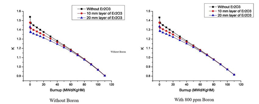
EPJ Web of Conferences 247, 02005 (2021)                                         https://doi.org/10.1051/epjconf/202124702005
PHYSOR2020

                   Reference pin                 1.66E+04
                   FCM pin                       2.91E+04
                   UO2                                                     3
                   FCM fuel                                               13
                   Helium Gas                                            0.31
                   Zirlo ™                                                17
                   FeCrAl                                                 16
                   Water                                                                   20,000

                                           Figure 1. Enrichment determination.

                     Figure 2. Fuel pin Temperature distribution of Reference and FCM assemblies.

         2.3. Optimization of FCM-TRISO Assembly

                                                            4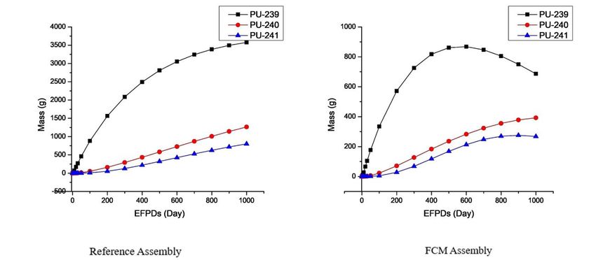
EPJ Web of Conferences 247, 02005 (2021)                                              https://doi.org/10.1051/epjconf/202124702005
PHYSOR2020

         The proposed FCM assembly is optimized for number and location of guide tubes and relative power
         distribution of fuel pins, nine guide tubes and their location is selected in such a way that maximum peaking
         factor of power shall not exceed 1.10. The reference assembly and optimized FCM fuel assembly is
         presented in figure 3.

                                   Figure 3. Geometry of Reference and FCM assemblies.

                                             3. RESULTS AND DISCUSSION
         3.1. Single Pin Criticality

         For reference and FCM assemblies, single pin is modelled and criticality calculation is performed using
         implicit and explicit methods of particles packing in fuel pin. One hundred thousand particles with 500
         active and 200 inactive cycles are used for this simulation and results of single pin infinite multiplication
         factors are presented in table III. The excess reactivity in the FCM pin is due to high enrichment and small
         loading of heavy metal.

                                     Table III. Single pin infinite multiplication factor.

                                                                           K- infinity        K- infinity
                              Assembly                K - infinity
                                                                         Implicit Model      Explicit model
                   Reference pin                    1.3750
                   FCM pin                                                   1.5770             1.57812

         3.2. Assembly Level Simulations

         3.2.1.   Burnup Analysis

         Depletion of reference assembly and FCM assembly is studied using the prescribed data in table I. High
         burnup of more than 100 MWd/kgHM in FCM assembly is observed compared to the typical 50
         MWd/kgHM of reference VVER-1000 assembly for the same number of EFPDs and Thermal Power (figure
         4). The reason of much larger burnup of FCM assembly is small loading of heavy metal and small amount
         of transuranic elements i.e. Pu-239, Pu-240 and Pu-241 production, which does not significantly contribute
         towards the fission rate and power generation as in the case of reference assembly.

                                                              5
EPJ Web of Conferences 247, 02005 (2021)                                               https://doi.org/10.1051/epjconf/202124702005
PHYSOR2020

                               Figure 4. Burnup Analysis of Reference and FCM assemblies.

         3.2.2.   Spectrum Analysis

         Energy spectrum of reference and FCM assembly, presented in figure 5 is simulated using 500 energy
         groups and without using soluble boron in the moderator. Excessive softening of the thermal flux in FCM
         assembly is attributed to the rapid rate of depletion of U-235 towards End of Cycle (EOC) and presence of
         carbon in the TRISO particles. The rapid rate of depletion of fissile material towards the EOC is the result
         of small production of transuranic elements in FCM assembly. Small production of transuranic elements
         leads to small contribution in fission rate and power generation as compared to reference UO 2 assembly.

                              Figure 5. Spectrum Analysis of Reference and FCM assemblies.

         3.2.3.   Material Inventories

         The production of transuranic elements Pu-239, Pu-240 and Pu-241 in FCM assembly (figure 6) are smaller
         as compared to reference assembly because of smaller initial loading of U-238 in FCM assembly. Small
         production of transuranic elements in FCM assembly makes it proliferation resistant. Although the
         proliferation is more linked to the quality of plutonium in the spent fuel, the quantity of plutonium isotopes
         is also a parameter to determine the possibility of reprocessing.

                                                               6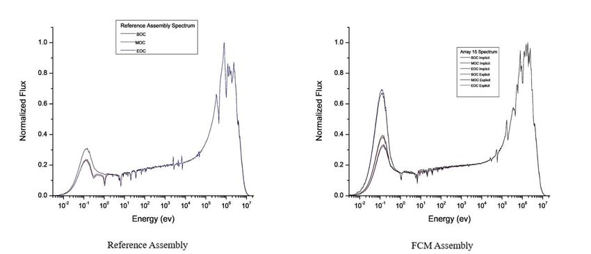
EPJ Web of Conferences 247, 02005 (2021)                                            https://doi.org/10.1051/epjconf/202124702005
PHYSOR2020

                             Figure 6. Material inventories of Reference and FCM assemblies.

         3.2.4.   Burnup analysis with burnable absorbers

         The suppression of excess reactivity in FCM assembly can be done by the addition of burnable absorbers
         in the fuel. A layer of burnable poison is added above the fuel kernel in TRISO particle, which makes it
         QUADRISO particle. Two type of burnable absorbers Gd2O3 and Er2O3 have been used and the fuel
         assembly lattice is again optimized with 22 fuel pins of QUADRISO particles embedded in SiC matrix.
         The maximum peaking factor remains 1.08 in FCM assembly. The cross section of Gadolinium is lager
         than Erbium so Gd2O3 shows larger suppression of reactivity in the beginning of cycle (BOC) but the
         burnup with Er2O3 is smooth. At the end of cycle ~2% and ~5%, mass of Gd and Er is left as residual
         respectively. Different layer thickness of burnable absorbers is used in QUADRISO particles and the burnup
         is presented in figure 7.

                                    Figure 7. Burnup analysis with burnable absorbers.

         3.2.5.   Temperature coefficients of reactivity

         Fuel temperature coefficient (FTC) and moderator temperature coefficient (MTC), presented in figure 8 are
         determined by simulating at variable fuel and moderator temperatures respectively. The FTC is calculated
         by changing the fuel temperature from 300K to 1500K and keeping all the conditions constant at cold zero

                                                             7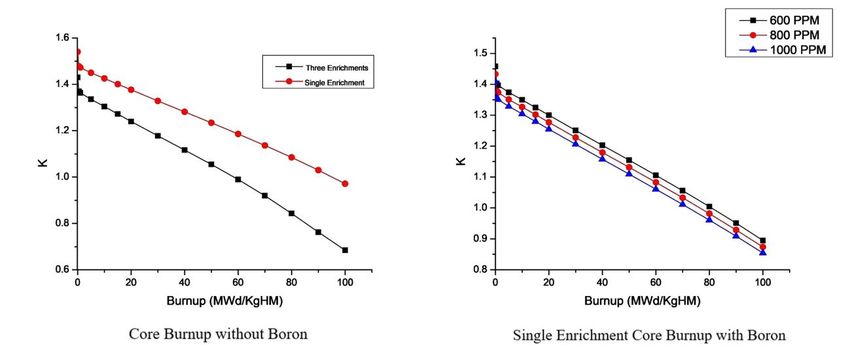
EPJ Web of Conferences 247, 02005 (2021)                                              https://doi.org/10.1051/epjconf/202124702005
PHYSOR2020

         power. Similarly, the MTC calculation is performed by changing the moderator temperature by 4K steps [7]
         and keeping the system temperature constant at inlet temperature. Both FTC and MTC are negative for full
         cycle but keep increasing to positive towards EOC; it is partly due to the excessive softening of the thermal
         spectrum towards EOC and partly due to presence of excessive carbon in the fuel. The negative trend of
         FTC and MTC remains same with soluble boron used in the moderator. The expected cycle length of FCM
         assembly based on negative temperature coefficients is ~800 EFPDs which is much larger than reference
         assembly.

                                       Figure 8. Temperature coefficients of reactivity.

         3.3. Full Core Simulations.

         VVER-1000 full core with 163 assemblies has been modelled using FCM assemblies as shown in figure 9.
         Two different problems with single enrichment and three enrichments are considered for burnup analysis.
         The corresponding enrichments of FCM assembly has been calculated based on the program explained in
         figure 1. Full core simulation data is provided in Appendix B.

                                       Figure 9. Full Core geometry with parameters.

         3.3.1.   Full core burnup analysis.

         Full core consisting of FCM assemblies is simulated using 1M particles with 300 inactive and 1000 active
         cycles to reduce the statistical fluctuations and standard deviation. Figure 10 presents the full core burnup

                                                              8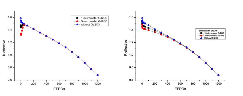
EPJ Web of Conferences 247, 02005 (2021)                                              https://doi.org/10.1051/epjconf/202124702005
PHYSOR2020

         of three enrichment problem and single enrichment problem. Considerably small cycle length is predicted
         in three-enrichment core but a large cycle length of about 700 EFPDs is predicted in single enrichment core.
         Following calculations are based on the single enrichment core. The smooth burnup is observed using
         different concentrations of boron.

                                           Figure 10. Full core burnup analysis.

         3.3.2.   Full core burnup with burnable absorbers.

         The burnup of single enrichment full core is simulated using burnable absorbers and 800-ppm boron. The
         burnable absorber is used in the form of QUADRISO particles. FCM assembly has 22 optimized pins (as
         explained in section 3.2.4) for QUADRISO particles. The suppression of reactivity with Gd2O3 is large
         early on (figure 11) and with the decrease of Gadolinium isotope, the burnup becomes smooth. Only ~2%
         mass of the Gadolinium is left after the full cycle. Using 800-ppm boron in the moderator further decreases
         the reactivity and burnup behavior remains same.

                              Figure 11. Full core burnup with Gd2O3 as Burnable Absorber.

         Another burnable absorber Er2O3 is simulated for full core burnup and the burnup behavior is found
         relatively smooth (figure 12) as compared to Gd2O3. Only ~5% residual mass of Erbium is recorded after
         full cycle. Using 800-ppm soluble boron in the moderator further decreases the reactivity and burnup
         behavior remains same.

                                                              9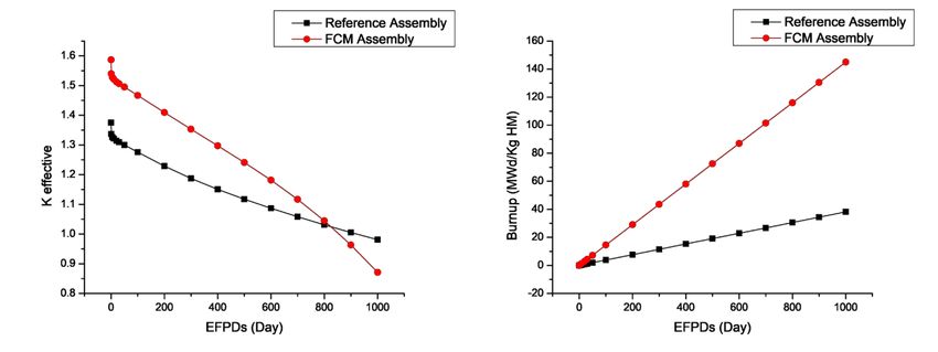
EPJ Web of Conferences 247, 02005 (2021)                                              https://doi.org/10.1051/epjconf/202124702005
PHYSOR2020

                              Figure 12. Full core burnup with Er2O3 as Burnable Absorber.

                                           4. CONCLUSION AND FUTURE WORK

         The purpose of this study is to perform a preliminary neutronics analysis of FCM-TRISO fuel to be used in
         VVER-1000 reactor core. The conversion of standard reference assembly to FCM assembly is based on
         assumptions like hydraulic diameter same as reference assembly, same thermal power, and low enrichment
         limit i.e. less than 20%. The detailed burnup analysis of FCM assembly and full core presents encouraging
         results. The temperature coefficients of reactivity FTC and MTC are negative for a longer cycle length.
         Another advantage of FCM fuel in VVER-1000 is very small production of transuranic elements, which
         makes it proliferation resistant. The innovative cladding concept of ferritic steel FeCrAl makes it accident
         tolerant because of no hydrogen production. Furthermore, in depth analysis of control assemblies and
         thermal hydraulics is required to assess the performance of FCM fuel in VVER-1000 reactor core.

                                                ACKNOWLEGEMENT
         The authors would like to acknowledge the support provided by China Scholarship Council via grant no
         2016GXZD60. INESEM, Tsinghua University provided the necessary resources to carry out this work.

                                                      REFERENCES

         1. Pope, Michael.A., Sonat Sen, R., Ougouage, Abderrafi.M., Touinou, Giles, Boer, Brian, 2012.
            Neutronic analysis of burning of transuranics in fully ceramic microencapsulated tri-isotropic particle-
            fuel in a PWR. Nuclear Engineering and Design. 252, 215–225.
         2. Kimura, K. et al., 2007. High burnup fuel cladding materials R&D for advanced nuclear systems.
            Journal of Nuclear Science and Technology. 44 (3), 323–328.
         3. Folsom, C., Xing, C., Jensen, C., Ben, H., Marshall, D.W., 2015. Experimental measurement and
            numerical modeling of the effective thermal conductivity of TRISO fuel compact. Journal of Nuclear
            Materials. 458, 198–205.
         4. J. Lappänan, “Serpent – a Continuous-energy Monte Carlo reactor physics burnup calculation code”,
            VTT Technical Research Center of Finland (2015).
         5. Peter, J.P., Robert, N.M., 2007. Estimation of maximum-coated particle fuel fraction compact packing
            fraction. Journal of Nuclear Materials. 361 (1), 18–29.
         6. Todreas, N.E., Kazimi, M.S.,” Nuclear Systems I: Thermal Hydraulics Fundamentals”, Taylor &
            Francis, 2nd Printing, USA 1993.
         7. Mourtazanos, K., Housiadas, C., Domis, M.A., 2001. Calculation of the moderator temperature
            coefficient of reactivity for water moderated reactor. Ann. Nucl. Environ. 28, 1773–1782.

                                                             10
EPJ Web of Conferences 247, 02005 (2021) https://doi.org/10.1051/epjconf/202124702005
PHYSOR2020
APPENDIX A
Description of TRISO Particles
TRISO and QUADRISO particle geometry is described in the following diagrams.
Figure 1. TRISO particle description
Figure 2. QUADRISO particle description
The specific parameters of TRISO particles are presented in the table. The parameters of the TRISO particle
such as fuel kernel diameter and the thickness of various layers depends upon the survival of particles under
the operational and accident conditions, these parameters are adjusted in such a way that the survival rate
99.5% at high temperatures such as 1600 C.
Table I. TRISO particle parameters.
Parameter Value and Units
Matrix SiC density 3.18 g/cm3
Fuel kernel Uranium Carbide (UC)
Kernel density 12.95 g/cm3 for UC
Diameter of fuel kernel 900 μm
Buffer density 1.05 g/cm3
Buffer thickness 75 μm
IPyC Density/thickness 1.9 g/cm3/30 μm
11EPJ Web of Conferences 247, 02005 (2021) https://doi.org/10.1051/epjconf/202124702005
PHYSOR2020
SiC PV thickness 35 μm
OPyC density/thickness 1.1 g/cm3/20 μm
APPENDIX B
Full Core Simulation Data
The following table presents the full core simulation data.
Table I. Description of full core simulation data
Parameters Reference Fuel FCM Fuel
Fuel pellet radius 0.3917 cm 0.6461 cm
Fuel material/matrix UO2 UC/SiC
Packing fraction – 35%
Enrichment 4.2% 15.97%
Heavy metal loading/FA 486.748 kg 128.298kg
HM% age of reference (100.0%) (26.35%)
Initial fissile loading/FA 20.43kg 20.43kg
Density of fuel 10.40 g/cm3 12.95 g/cm3
Helium gap thickness 0.0085 cm 0.0085 cm
Clad thickness 0.069 cm 0.057 cm
No. of fuel rods 312 160
Fuel rod radii (outer) 0.4572 cm 0.7116 cm
No. of guide tubes 19 9
Guide tube radii (outer/inner) 0.630 cm/0.550 cm 0.8613 cm//0.8043
cm
Helium density 0.00222 g/cm3 0.00222 g/cm3
Density of clad material (FeCrAl) – 7.25 g/cm3
Density of moderator (H2O) 0.72701 g/cm3 0.72701 g/cm3
Fuel temperature (ave) 990.0 K 950.0 K
Cladding temperature (ave) 600.0 K 600.0 K
Moderator temperature (ave) 574.0 K 574.0 K
Pin pitch 1.275 cm 1.785 cm
Fuel assembly pitch 21.55 cm 21.55 cm
Fuel assembly height 353.0 cm 353.0 cm
Fuel assembly power 18.6 MW 18.6 MW
Number of Assemblies 163 163
Total Thermal Power of Core 3030 MWth 3030 MWth
RPV material SS304 SS304
Operating Pressure 15.7 MPa 15.7 MPa
12You can also read