ISOLATED DC-DC CONVERTER CHASSIS MOUNT CQB100W-110SXX-CMFC(D) SERIES APPLICATION NOTE - Cincon
←
→
Page content transcription
If your browser does not render page correctly, please read the page content below

CHASSIS MOUNT CQB100W-110SXX-CMFC(D) Series
                                      Application Note V10 May 2020

               ISOLATED DC-DC CONVERTER
                     CHASSIS MOUNT
             CQB100W-110SXX-CMFC(D) SERIES
                   APPLICATION NOTE

Approved By:

           Department             Approved By       Checked By   Written By
                                    Enoch             Astray      Jiaweii

    Research and Development
           Department                                 Jacky

                                     Ryan             Benny

        Quality Assurance
          Department

                                                1
CHASSIS MOUNT CQB100W-110SXX-CMFC(D) Series
                                                                       Application Note V10 May 2020

                                                                           Contents
1. Introduction ..............................................................................................................................3
2. DC-DC Converter Features .....................................................................................................3
3. Electrical Circuit Diagram ........................................................................................................3
4. Terminal Block .........................................................................................................................3
5. Technical Specifications ..........................................................................................................4
6. Main Features and Functions ..................................................................................................8
  6.1 Operating Temperature Range ....................................................................................................................... 8
  6.2 Output Voltage Adjustment ............................................................................................................................. 8
  6.3 Over Current Protection .................................................................................................................................. 8
  6.4 Output Over Voltage Protection ...................................................................................................................... 8
  6.5 Remote On/Off................................................................................................................................................ 8
  6.6 UVLO (Under Voltage Lock Out) .................................................................................................................... 8
  6.7 Over Temperature Protection ......................................................................................................................... 9
7. Applications .............................................................................................................................9
  7.1 Connection for standard use ........................................................................................................................... 9
  7.2 Convection Requirements for Cooling ............................................................................................................ 9
  7.3 Thermal Considerations .................................................................................................................................. 9
  7.4 Derating .......................................................................................................................................................... 9
  7.5 Power Derating ............................................................................................................................................. 10
  7.6 Hold up Time ................................................................................................................................................ 12
  7.7 Full Brick Heat Sinks: .................................................................................................................................... 13
  7.8 Efficiency VS. Load....................................................................................................................................... 14
  7.9 Test Set-Up................................................................................................................................................... 15
  7.10 Output Voltage Adjustment ......................................................................................................................... 15
  7.11 Output Remote Sensing ............................................................................................................................. 15
  7.12 Output Ripple and Noise ............................................................................................................................. 16
  7.13 Output Capacitance .................................................................................................................................... 16
  7.14 Remote On/Off Circuit ................................................................................................................................ 16
8. Safety & EMC ........................................................................................................................17
  8.1 Input Fusing and Safety Considerations ....................................................................................................... 17
  8.2 EMC Considerations ..................................................................................................................................... 17
9. Part Number ..........................................................................................................................22
10. Mechanical Specifications ...................................................................................................22
  10.1 Mechanical Outline Diagrams ..................................................................................................................... 22

                                                                                   2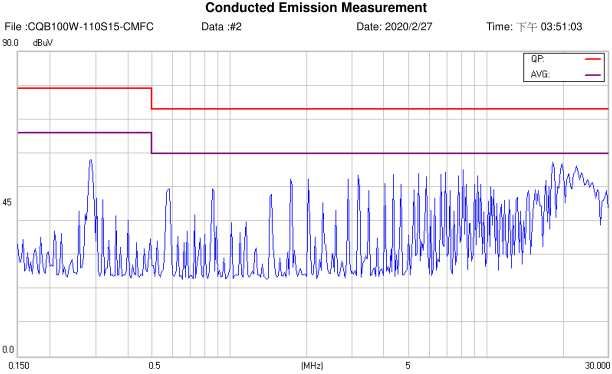
CHASSIS MOUNT CQB100W-110SXX-CMFC(D) Series
                                                Application Note V10 May 2020

1. Introduction                                                2. DC-DC Converter Features
The CQB100W-110SXX-CMFC(D) series of chassis                    • 100W Isolated Output
mountable DC-DC converters offers 150 watts of                  • Efficiency to 91%
output power @ single output voltages of 5, 12, 15, 24,
28, 48VDC. It has a wide (4:1) input voltage range of           • Fixed Switching Frequency
43 to 160VDC (110VDC nominal) and 3000VDC basic                 • 4:1 Input Range
isolation.                                                      • Regulated Outputs
High efficiency up to 91%, allowing case operating              • Remote On/Off
temperature range of –40°C to 100°C. An optional heat
                                                                • Low No Load Power Consumption
sink is available to extend the full power range of the
unit. Very low no load power consumption (15mA), an             • Over Temperature Protection
ideal solution for energy critical systems.                     • Over Voltage/Current Protection
Built-in EMI EN50155, EN50121-3-2 filter. Meet                  • Continuous Short Circuit Protection
EN45545. The standard control functions include                 • Build-In EMI Filter
remote on/off (positive or negative) and +10%, -10%
                                                                • Fire & Smoke Meets EN45545-2
adjustable output voltage.
                                                                • Shock & Vibration Meets EN50155 (EN61373)
Fully protected against input UVLO (under voltage lock
out), output over-current, output over-voltage and over-        • Safety Meets UL60950-1, EN60950-1
temperature and continuous short circuit conditions.              and IEC60950-1
CQB100W-110SXX-CMFC(D) series is designed                       • UL60950-1 2nd (Basic Insulation) Approval
primarily for common railway applications of 72V, 96V,            for DC Modules (Except 15Vout)
110V nominal voltage and also suitable for distributed
power architectures, telecommunications, battery                • EN50155:2007 for EMC, Environmental
operated equipment and industrial applications.                   and Characteristic

3. Electrical Circuit Diagram

4. Terminal Block
Input and Output Terminal Block
     Terminal Type     Screw Torque Value (Kgf-cm)         Suitable Electric Wire (AWG)       Current Rating (max.)
    EK500V-XXP or
                                   5                                    12-24                           20A
       Equivalent

                                                           3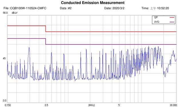
CHASSIS MOUNT CQB100W-110SXX-CMFC(D) Series
                                                     Application Note V10 May 2020

5. Technical Specifications
(All specifications are typical at nominal input, full load at 25°C unless otherwise noted.)

ABSOLUTE MAXIMUM RATINGS
PARAMETER                   NOTES and CONDITIONS                     Device      Min.     Typical     Max.    Units
Input Voltage
 Continuous                                                            All        -0.3                160      Vdc
 Transient                  100ms                                      All                            200      Vdc
Operating Case
                                                                       All        -40                 100      °C
Temperature
Storage Temperature                                                    All        -40                 105      °C
                            1 minute; Input/Output                     All                            3000     Vdc
Isolation Voltage           1 minute; Input/Case                       All                            2250     Vdc
                            1 minute; Output/Case                      All                            500      Vac

INPUT CHARACTERISTICS
PARAMETER                   NOTES and CONDITIONS                     Device      Min.     Typical     Max.    Units
Operating Input Voltage                                                All        43           110    160      Vdc
Input Under Voltage Lockout
  Turn-On Voltage
                                                                       All        40.5         41.5   42.5     Vdc
  Threshold
  Turn-Off Voltage
                                                                       All        37.5         38.5   39.5     Vdc
  Threshold
  Lockout Hysteresis
                                                                       All                     3.0             Vdc
  Voltage
Maximum Input Current       100% Load, Vin=110V for All                All                     1.5             A
                                                                     110S05                    15
                                                                     110S12                    15
                                                                     110S15                    15
No-Load Input Current                                                                                          mA
                                                                     110S24                    15
                                                                     110S28                    15
                                                                     110S48                    15

OUTPUT CHARACTERISTICS
PARAMETER                   NOTES and CONDITIONS                     Device      Min.     Typical     Max.    Units
                                                                     Vo=5.0V     4.95           5     5.05
                                                                     Vo=12V      11.88         12     12.12
                                                                     Vo=15V      14.85         15     15.15
Output Voltage Set Point    Vin=Nominal Vin, Io = Io_max, TC =25°C                                             Vdc
                                                                     Vo=24V      23.76         24     24.24
                                                                     Vo=28V      27.72         28     28.28
                                                                     Vo=48V      47.52         48     48.48
Output Voltage Regulation
                                                                     110S05                           ±0.5     %
 Load Regulation            Io=Io_min to Io_max
                                                                      Other                           ±0.2     %
 Line Regulation            Vin=Low Line to High Line                  All                            ±0.2     %
 Temperature Coefficient    TC=-40°C to 105°C                          All                            ±0.02   %/°C

                                                             4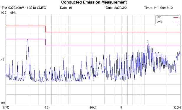
CHASSIS MOUNT CQB100W-110SXX-CMFC(D) Series
                                                    Application Note V10 May 2020

PARAMETER                  NOTES and CONDITIONS                     Device    Min.   Typical   Max.    Units
Output Voltage Ripple and Noise (5Hz to 20MHz Bandwidth)
                                                                    Vo=5.0V                     60
                                                                    Vo=12V                     100
                                                                    Vo=15V                     100
 Peak-to-Peak                                                                                           mV
                                                                    Vo=24V                     200
                                                                    Vo=28V                     200
                           Full Load, 1uF Ceramic Capacitor.        Vo=48V                     300
                           See 7.12                                 Vo=5.0V                     40
                                                                    Vo=12V                      40
                                                                    Vo=15V                      40
 RMS.                                                                                                   mV
                                                                    Vo=24V                     100
                                                                    Vo=28V                     100
                                                                    Vo=48V                     150
                                                                    Vo=5.0V    0                20
                                                                    Vo=12V     0                8.4
Operating Output Current                                            Vo=15V     0                6.7
                                                                                                        A
Range                                                               Vo=24V     0                4.2
                                                                    Vo=28V     0                3.6
                                                                    Vo=48V     0                2.1
Output DC Current Limit
                           Hiccup Mode. Auto Recovery. See 6.3        All     110     125      160      %
Inception
                                                                    110S05     0               20000
                                                                    110S12     0               8400
Maximum Output                                                      110S15     0               6700
                           Full Load (resistive)                                                        uF
Capacitance                                                         110S24     0               4200
                                                                    110S28     0               3600
                                                                    110S48     0               1000
                                                                    11015     -20              +10
Output Voltage Trim        Pout=max Rated Power, Trim Adj. Range
                                                                                                        %
Range                      (By VR1), See 7.10
                                                                    Others    -10              +10
Output Over Voltage
                           Limited Voltage, See 6.4                   All     115     125      140      %
Protection
DYNAMIC CHARACTERISTICS
PARAMETER                  NOTES and CONDITIONS                     Device    Min.   Typical   Max.    Units
Output Voltage Current Transient

 Error Band                75% to 100% of Io_max Step Load Change     All                       ±5      %
                           di/dt=0.1A/us
 Recovery Time             (within 1% Vout Nominal)                   All                      250      us

Turn-On Delay and Rise
                           Full load (Constant Resistive Load)
Time
Turn-On Delay Time,
                           Von/off to 10%Vo_set                       All              50               ms
From On/Off Control
 Turn-On Delay Time,
                           Vin_min to 10%Vo_set                       All              50               ms
 From Input
 Output Voltage Rise
                           10%Vo_set to 90%Vo_set                     All              50               ms
 Time

                                                           5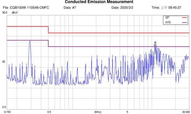
CHASSIS MOUNT CQB100W-110SXX-CMFC(D) Series
                                                       Application Note V10 May 2020

EFFICIENCY
PARAMETER                   NOTES and CONDITIONS                   Device   Min.      Typical   Max.   Units
                                                                   110S05               89
                                                                   110S12               91
                            Vin=110V                               110S15               91
100% Load                                                                                               %
                            See 7.8                                110S24               88
                                                                   110S28               88
                                                                   110S48              89.5

ISOLATION CHARACTERISTICS
PARAMETER                   NOTES and CONDITIONS                   Device   Min.      Typical   Max.   Units
                            1 minute; Input/Output                   All                        3000    Vdc
Isolation Voltage           1 minute; Input/Case                     All                        2250    Vdc
                            1 minute; Output/Case                    All                        500     Vac
Isolation Resistance        Input/Output                             All     100                       MΩ
                            Input/Output (DC Module)                 All               1500
                                                                   110S05              4930
                                                                   110S12              7680
                                                                   110S15              4580
                            Input/Case
                                                                   110S24              4800
                                                                   110S28              6040
Isolation Capacitance                                              110S48              5820             pF
                                                                   110S05              2200
                                                                   110S12              5500
                                                                   110S15              9400
                            Output/Case
                                                                   110S24              3700
                                                                   110S28              3200
                                                                   110S48              5500

FEATURE CHARACTERISTICS
PARAMETER                   NOTES and CONDITIONS                   Device   Min.      Typical   Max.   Units
Switching Frequency         Pulse Wide Modulation (PWM), Fixed       All     270       300      330    KHz
On/Off Control, Positive Remote On/Off Logic, Refer to –Vin Pin.
 Logic Low (Module Off)     Von/off at Ion/off=1.0mA                 All      0                 1.2     V
                                                                            3.5 or
 Logic High (Module On)     Von/off at Ion/off=0.0uA                 All    Open                160     V
                                                                            Circuit
On/Off Control, Negative Remote On/Off Logic, Refer to –Vin Pin
                                                                            3.5 or
 Logic High (Module Off)    Von/off at Ion/off=0.0uA                 All    Open                160     V
                                                                            Circuit
 Logic Low (Module On)      Von/off at Ion/off=1.0mA                 All      0                 1.2     V
On/Off Current (for Both
                            Ion/off at Von/off=0.0V                  All                0.3      1      mA
Remote On/Off Logic)
Leakage Current (for Both
                            Logic High, Von/off=15V                  All                         30     uA
Remote On/Off Logic)
Off Converter Input
                            Shutdown Input Idle Current              All                5        10     mA
Current

                                                            6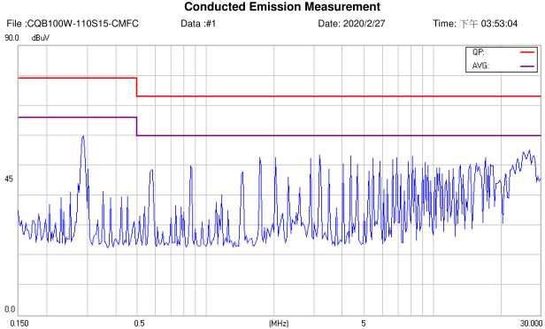
CHASSIS MOUNT CQB100W-110SXX-CMFC(D) Series
                                                  Application Note V10 May 2020

PARAMETER                  NOTES and CONDITIONS                        Device       Min.      Typical   Max.     Units
Output Over Voltage
                                                                         All         115        125     140        %
Protection
Over Temperature
                                                                         All                    105                °C
Shutdown
                           Aluminum Base Plate Temperature
Over Temperature
                                                                         All                    100                °C
Recovery
GENERAL SPECIFICATIONS
PARAMETER                  NOTES and CONDITIONS                        Device       Min.      Typical   Max.     Units
                                                                       110S05
                                                                       110S12                   514
                           Io=100% of Io_max;                          110S15                                      K
MTBF                                                                                            611
                           MIL-HDBK - 217F_Notice 1, GB, 25°C          110S28                                    hours
                                                                       110S24
                                                                       110S48                   728
                                                                       -CMFC                    215
Weight                     CQB100W-110SXX                                                                        grams
                                                                       -CMFD                    300
Terminal Type              EK500V-XXP, suitable electric wire: 24~12AWG (IEC 0.5~2.5mm2 )
Base Plate Material        Aluminum
Potting Material           UL 94V-0(DC MODULE)
Shock/Vibration            Meets EN50155 (EN61373)
Humidity                   95% RH max. Non Condensing
Altitude                   3000m Operating Altitude, 12000m Transport Altitude
Thermal Shock              MIL-STD-810F
EMI                        Meets EN55011, EN55022 & EN50155, see 8.2 EN55032                               Class A
ESD                        EN61000-4-2           Level 3: Air ±8kV, Contact ±6kV                        Perf. Criteria A
Radiated immunity          EN61000-4-3           Level 3: 80~1000MHz, 20V/m                             Perf. Criteria A
                           EN61000-4-4           Level 3: On power input port, ±2kV, external input
Fast Transient                                                                                          Perf. Criteria A
                           capacitor required, see 8.1
Surge                      EN61000-4-5           Level 4: Line to earth, ±4kV, Line to line, ±2kV       Perf. Criteria A
Conducted immunity         EN61000-4-6           Level 3: 0.15~80MHz, 10V                               Perf. Criteria A
Interruptions of Voltage                                                                                Perf. Criteria B
                           EN50155               Class S2: 10ms Interruptions, See 7.6
Supply
Supply Change Over         EN50155               Class C2: During a supply break of 30 ms               Perf. Criteria B
Fire & Smoke               Meets EN45545-2

                                                           7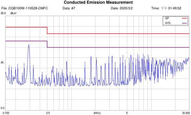
CHASSIS MOUNT CQB100W-110SXX-CMFC(D) Series
                                                   Application Note V10 May 2020

6. Main Features and Functions                                   6.5 Remote On/Off
                                                                 The CQB100W-110SXX-CMFC(D) series allows the
6.1 Operating Temperature Range                                  user to switch the module on and off electronically
The CQB100W-110SXX-CMFC(D) series converters                     with the remote on/off feature. All models are available
can be operated within a wide case temperature range             in “positive logic” and “negative logic” (optional)
of -40°C to 100°C. Consideration must be given to the            versions. The converter turns on if the remote on/off
derating curves when ascertaining maximum power                  pin is high (>3.5Vdc to 160Vdc or open circuit). Setting
that can be drawn from the converter. The maximum                the pin low (0 to3.5Vdc to 160Vdc or open circuit).
    •   Heat sink optional                                       The converter turns on if the on/off pin input is low (0
                                                                 to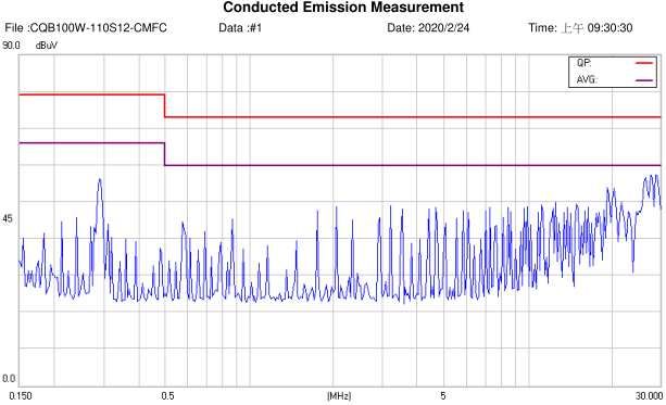
CHASSIS MOUNT CQB100W-110SXX-CMFC(D) Series
                                                  Application Note V10 May 2020

6.7 Over Temperature Protection                                  7.2 Convection Requirements for Cooling
These modules have an over temperature protection                To predict the approximate cooling needed for the
circuit to safeguard against thermal damage.                     quarter brick module, refer to the power derating
Shutdown occurs with the maximum case reference                  curves in section 7.5. These derating curves are
temperature is exceeded. The module will restart                 approximations of the ambient temperatures and
when the case temperature falls below over                       airflows required to keep the power module
temperature recovery threshold. Please measured at               temperature below its maximum rating. Once the
point A. (Measuring point A refer to the following figure)       module is assembled in the actual system, the
                                                                 module’s aluminum plate (point A) and aluminum
                                                                 capacitor (point B) temperature should be monitored
                                                                 to ensure it does not exceed 100°C.
                                                                 7.3 Thermal Considerations
                                                                 The power module operates in a variety of thermal
                                                                 environments; however, sufficient cooling should be
                                                                 provided to help ensure reliable operation of the unit.
                                                                 Heat is removed by conduction, convection, and
                                                                 radiation to the surrounding environment. The
                                                                 example is presented in section 7.5. The power
                                                                 output of the module should not be allowed to exceed
                                                                 rated power (Vo_set x Io_max).
                                                                 7.4 Derating
                                                                 The following figures are ambient derating curve of
                                                                 CQB100W-110SXX-CMFC(D) based on the aluminum
                                                                 base plate temperature. When operating the
                                                                 CQB100W-110SXX-CMFC(D) series, proper derating
                                                                 or cooling is needed. The maximum case temperature
                                                                 under any operating condition should not exceed
7. Applications                                                  100°C. (Measuring point A and measuring point B
                                                                 refer to the section 6.7)
7.1 Connection for standard use
The connection for standard use is shown below. An
external output capacitors (C1) is recommended to
reduce output ripple and noise, output capacitor
recommended 1 uF ceramic capacitor.

                                                                 Ambient Derating Curves at Nominal Line, Full Load and
                                                                 Natural Convection
     Symbol         Component              Reference
       F1            Input fuse           Section 8.1
               Internal input noise
  Noise Filter                            Section 8.2
                        filter
                External Remote
 Remote On/Off                           Section 7.14
                  On/Off control
                  Internal output
     Trim      voltage adjustment        Section 7.10
               By variable resistor
                                           Section
    Heat sink      External heat sink
                                          7.4/7.5/7.7
+Sense/-Sense               --           Section 7.11

                                                             9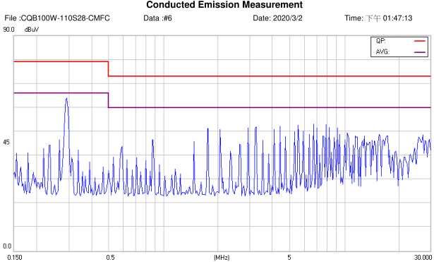
CHASSIS MOUNT CQB100W-110SXX-CMFC(D) Series
                                         Application Note V10 May 2020

7.5 Power Derating
The operating case temperature range of CQB100W-110SXX-CMFC(D) series is -40°C to +100°C. When
operating the CQB100W-110SXX-CMFC(D) series, proper derating or cooling is needed. The maximum case
temperature under any operating condition should not exceed 100°C.
The following curve is the de-rating curve of CQB100W-110SXX-CMFC(D) series with heat sink.
The test condition refer to following figures.

                                                10
CHASSIS MOUNT CQB100W-110SXX-CMFC(D) Series
Application Note V10 May 2020
Power Dissipated v s Ambient Temperature and Air Flow with heatsink
18 HEATSINKS TYPICAL Rca
16 Heatsin k with M- Heatsink with M-B012 2.6 ℃/W
B01 2
14 Heatsink with iron plate
Power Disspated ,Pd(Watts)
2.1 ℃/W
12 Heatsin k with iron (17x17x0.04inch)
10 plate(1 7x1 7x0 .04 inch
)
8
6
4
2
0
0 10 20 30 40 50 60 70 80 90 100
Ambient Temperature ,Ta(Deg. C)
Example with heat sink FBL254 (B-012):
How to make a CQB100W-110S24-CMFC operating at nominal line voltage, an output current of 4.2A, and a
maximum ambient temperature of 60℃?
Solution:
Given:
Vin=110Vdc, Vo=24Vdc, Io=4.2A
Determine Power dissipation (Pd):
Pd=Pi-Po=Po(1-η)/η
Pd=24.0×4.2×(1-0.88)/0.88=13.75Watts
Determine airflow:
Given: Pd=13.75W and Ta=60℃
Check above Power de-rating curve:
Heat sink with B-012
Verify:
Maximum temperature rise is△T = Pd × Rca=13.75×2.6=35.75℃
Maximum case temperature is Tc=Ta+△T=95.75℃CHASSIS MOUNT CQB100W-110SXX-CMFC(D) Series
Application Note V10 May 2020
7.6 Hold up Time
Hold up time is defined as the duration of time that DC/DC converter output will remain active following a loss of
input power.
The test condition and test curve refer to following figures.
120 CQB100W-110S48-CMFC Hold Up Time
110
100
90
Hold Up Time [ms]
80
43Vin
70
48Vin
60
72Vin
50
40 96Vin
30 110Vin
20 160Vin
10
0
10 20 30 40 50 60 70 80 90 100
Output Power Pout [W]
The external circuit about extend hold up time refer to following figure.
12CHASSIS MOUNT CQB100W-110SXX-CMFC(D) Series
Application Note V10 May 2020
7.7 Full Brick Heat Sinks:
Heat-sink FBL254 (M-B012 )
All Dimension In mm
Longitudinal Fins
25.4
116.8 +0 5.4
2-
-0.1
R0
5.1
106.7±0.1 2.7
.9
5.05
9.6
14.5
1.4
8
6-R
8
1.0 4
50.8±0.1
61 -0.1
5 0.
-R
+0
10 0.2
32
8
R
4-
8
2.1
0.30
8
90°
9.6
4-
3 .3
0.5
2-
1.8
4.2
R0
.8
Heat Sink (Clear Mounting Inserts Φ3.3mm Through): 116.8*61*25.4 FBL254 (M-B012) G6620090204
Thermal PAD PF01: PMP-P400 60*115.8*0.23 (G6135041073)
Screw Nut K320N: M3*20L (G75A1300052) & NH+WOM3*P0.5N (G75A2440392)
Heat-sink FBL254TM-C997
All Dimension In mm
Longitudinal Fins
116.8±0.3
25.4
106.7±0.2 5.05 5.4
5.1 2-R0.9
2.7
9.6
0.3
8.0
1.4
8.0
6-R1.05
61.0±0.5
50.8±0.2
10-R0.4
8.0
4-R0.2
8.0
C0.3
C0.3
8.0
2.1
9.6
90°
4-M3*0.5 0.5
2-R0.8
4.2
Heat Sink (Mounting Inserts M3*0.5 Through): 116.8*61*25.4 FBL254T(M-C997) G6620980201
Thermal PAD PF01: PMP-P400 60*115.8*0.23 (G6135041073)
Screw & Washer: M3*20L (G75A1300052) & WS3.2N (G75A47A0752)
AIR FLOW RATE TYPICAL Rca
Natural Convection
2.4 ℃/W
20ft./min. (0.1m/s)
100 ft./min. (0.5m/s) 1.76 ℃/W
200 ft./min. (1.0m/s) 1.17 ℃/W
300 ft./min. (1.5m/s) 1.00 ℃/W
400 ft./min. (2.0m/s) 0.83 ℃/W
13CHASSIS MOUNT CQB100W-110SXX-CMFC(D) Series
Application Note V10 May 2020
7.8 Efficiency VS. Load
CQB100W-110S05-CMFC (Eff Vs Io) CQB100W-110S12-CMFC (Eff Vs Io)
100% 100%
Efficiency (%)
Efficiency (%)
90% 90%
80% 43V 80% 43V
72V 72V
70% 96V 70% 96V
110V 110V
60% 60%
160V 160V
50% 50%
10% 20% 30% 40% 50% 60% 70% 80% 90% 100% 10% 20% 30% 40% 50% 60% 70% 80% 90% 100%
Current Load (%) Current Load (%)
CQB100W-110S15-CMFC (Eff Vs Io) CQB100W-110S24-CMFC (Eff Vs Io)
100% 100%
90%
Efficiency (%)
Efficiency (%)
90%
80% 43V 80% 43V
72V 72V
70% 96V 70% 96V
110V 110V
60% 60%
160V 160V
50% 50%
10% 20% 30% 40% 50% 60% 70% 80% 90% 100% 10% 20% 30% 40% 50% 60% 70% 80% 90% 100%
Current Load (%) Current Load (%)
CQB100W-110S28-CMFC (Eff Vs Io) CQB100W-110S48-CMFC (Eff Vs Io)
100% 100%
Efficiency (%)
Efficiency (%)
90% 90%
80% 43V 80% 43V
72V 72V
70% 96V 70%
96V
110V 110V
60% 60%
160V 160V
50% 50%
10% 20% 30% 40% 50% 60% 70% 80% 90% 100% 10% 20% 30% 40% 50% 60% 70% 80% 90% 100%
Current Load (%) Current Load (%)
14CHASSIS MOUNT CQB100W-110SXX-CMFC(D) Series
Application Note V10 May 2020
7.9 Test Set-Up
The basic test set-up to measure parameters such as
efficiency and load regulation is shown below. When
testing the modules under any transient conditions
please ensure that the transient response of the
source is sufficient to power the equipment under test.
We can calculate:
• Efficiency
• Load regulation and line regulation. 7.11 Output Remote Sensing
The value of efficiency is defined as: The CQB100W-110SXX-CMFC(D) series converter
has the capability to remotely sense both lines of its
Vo × Io
η = × 100% output. This feature moves the effective output
Vin × Iin voltage regulation point from the output of the unit to
the point of connection of the remote sense pins.
Where:
This feature automatically adjusts the real output
Vo is output voltage, voltage of the CQB100W-110SXX-CMFC(D) series
Io is output current, in order to compensate for voltage drops in
Vin is input voltage, distribution and maintain a regulated voltage at the
point of load. The remote-sense voltage range
Iin is input current.
is:
The value of load regulation is defined as:
[(+Vout) - (-Vout)] – [(+Sense) – (-Sense)] ≦
VFL − VNL
Load .reg = ×100% 10% of Vo_nominal
VNL
Where: When remote sensing is used, please remove the
VFL is the output voltage at full load. jumper of CN3. When remote sense is in use, the
VNL is the output voltage at no load. sense should be connected by twisted-pair wire or
shield wire. If the sensing patterns short, heavy
The value of line regulation is defined as: current flows and the pattern may be damaged.
VHL − VLL Output voltage might become unstable because of
Line.reg = ×100% impedance of wiring and load condition when length
VLL of wire is exceeding 400mm. This is shown in the
Where: VHL is the output voltage of maximum input schematic below.
voltage at full load. VLL is the output voltage of
minimum input voltage at full load.
CQB100W-110SXX-CMFC(D) Series Test Setup
7.10 Output Voltage Adjustment When the CMFC module are shipped from a
Output may be externally trimmed (±10%) with a factory, they come with a dedicated jumper being
variable resistance as shown. Output voltage can be mounted on CN3. If the remote sense feature is not
adjusted by internal variable resistor. Turning internal to be used, the sense pins should be connected
variable resistor clockwise reduces the output voltage locally. The +Sense pin should be connected to the
and counterclockwise increases the output voltage. +Vout pin at the module and the -Sense pin should
be connected to the -Vout pin at the module. Wire
between +Sense and +Vout and between -Sense
and –Vout as short as possible. Loop wiring should
be avoided. The converter might become unstable
by noise coming from poor wiring. This is shown in
the schematic below.
15CHASSIS MOUNT CQB100W-110SXX-CMFC(D) Series
Application Note V10 May 2020
Note: Although the output voltage can be varied
(increased or decreased) by both remote sense and
trim, the maximum variation for the output voltage is
the larger of the two values not the sum of the values.
7.13 Output Capacitance
The output power delivered by the module is defined The CQB100W-110SXX-CMFC(D) series converters
as the voltage at the output terminals multiplied by the provide unconditional stability with or without external
output current. Using remote sense and trim can cause capacitors. For good transient response, low ESR
the output voltage to increase and consequently output capacitors should be located close to the point
increase the power output of the module if output of load (CHASSIS MOUNT CQB100W-110SXX-CMFC(D) Series
Application Note V10 May 2020
8. Safety & EMC
8.1 Input Fusing and Safety Considerations
The CQB100W-110SXX-CMFC(D) series converters have no internal fuse. In order to achieve maximum safety
and system protection, always use an input line fuse. We recommended a 6A time delay fuse for all models.
CMFC module have a transient voltage suppressor diode (TVS) across the input terminal to protect the unit
against surge or spike voltage and input reverse voltage (as shown).
8.2 EMC Considerations
EMI Test standard: EN55022 / EN55032 Class A Conducted Emission
Test Condition: Input Voltage: Nominal, Output Load: Full Load
(1) EMI and conducted noise meet EN55011 / EN55022 / EN50155 Class A:
Connection circuit for conducted EMI Class A testing
17CHASSIS MOUNT CQB100W-110SXX-CMFC(D) Series
Application Note V10 May 2020
CQB100W-110S05-CMFC(D) CQB100W-110S05-CMFC(D)
Line Neutral
CQB100W-110S12-CMFC(D) CQB100W-110S12-CMFC(D)
Line Neutral
CQB100W-110S15-CMFC(D) CQB100W-110S15-CMFC(D)
Line Neutral
CQB100W-110S24-CMFC(D) CQB100W-110S24-CMFC(D)
Line Neutral
18CHASSIS MOUNT CQB100W-110SXX-CMFC(D) Series
Application Note V10 May 2020
CQB100W-110S28-CMFC(D) CQB100W-110S28-CMFC(D)
Line Neutral
CQB100W-110S48-CMFC(D) CQB100W-110S48-CMFC(D)
Line Neutral
(2) The external filter is required for output conducted noise meet EN50155 : EN50121-3-2:2015 Class A:
19CHASSIS MOUNT CQB100W-110SXX-CMFC(D) Series
Application Note V10 May 2020
Connection circuit for conducted EMI Class A testing
Note: C1, C2 are 4.7uF ceramic capacitors
C5, C6 are 0.1uF ceramic capacitors.
L1: 0.47mH or equivalent
CQB100W-110S05-CMFC(D) CQB100W-110S05-CMFC(D)
Positive Negative
CQB100W-110S12-CMFC(D) CQB100W-110S12-CMFC(D)
Positive Negative
CQB100W-110S15-CMFC(D) CQB100W-110S15-CMFC(D)
Positive Negative
20CHASSIS MOUNT CQB100W-110SXX-CMFC(D) Series
Application Note V10 May 2020
CQB100W-110S24-CMFC(D) CQB100W-110S24-CMFC(D)
Positive Negative
CQB100W-110S28-CMFC(D) CQB100W-110S28-CMFC(D)
Positive Negative
CQB100W-110S48-CMFC(D) CQB100W-110S48-CMFC(D)
Positive Negative
21CHASSIS MOUNT CQB100W-110SXX-CMFC(D) Series
Application Note V10 May 2020
9. Part Number
Format: CQB100W – III OXXL-YYYZ
Nominal
Number of Remote On/Off
Parameter Series Input Output Voltage Chassis Mount Type
Outputs Logic
Voltage
Symbol CQB100W- III O XX L YYY Z (Option)
05: 5.0 Volts
12: 12 Volts Chassis
110: 110 15: 15 Volts None: Positive Mount C: Open Frame
Value CQB100W- S: Single CMF
Volts 24: 24 Volts N: Negative Built in D: with Cover
Filter
28: 28 Volts
48: 48 Volts
10. Mechanical Specifications
10.1 Mechanical Outline Diagrams
All Dimensions In Inches (mm)
Tolerance Inches: X.XX=±0.02, X.XXX=±0.010
Millimeters: X.X=±0.5, X.XX=±0.25
CMFC CMFD with Cover
4.60[116.8] 4.60[116.8]
4.200[106.68] 4.200[106.68]
0.200[5.08] CN1&CN2
0.200[5.08] PIN CONNECTION
Pin Function
1 +V Input
2 -V Input
VR1 VR1 3 Remote
2.000[50.80]
2.000[50.80]
1 5 4 Case
2.40[61.0]
2.49[63.4]
1 5
CN1 CN2 CN1 CN2 +V Output
2 6 2 6 5
0.248[6.31]
0.200[5.08]
3 7 3 7 6 +V Output
4 8 4 8
7 -V Output
CN3 CN3 8 -V Output
CN3
PIN CONNECTION
1 2 3 4 Pin Function
1 -V Output
1.26[32.0]
1 2 3 4
1.35[34.2]
2 -Sense
0.523[13.30]
3 +Sense
0.523[13.30]
CN3
CN3 4 +V Output
CQB100W-110SXX-CMFC(D) Mechanical Outline Diagram
CINCON ELECTRONICS CO., LTD.
Headquarters: Factory: Cincon North America:
14F, No.306, Sec.4, Hsin Yi Rd. No. 8-1, Fu Kung Rd. 1655Mesa Verde Ave. Ste 180
Taipei, Taiwan Fu Hsing Industrial Park Ventura, CA93003
Tel: 886-2-27086210 Fu Hsing Hsiang, Tel: 805-639-3350
Fax: 886-2-27029852 ChangHua Hsien, Taiwan Fax: 805-639-4101
E-mail: support@cincon.com.tw Tel: 886-4-7690261 E-mail: info@cincon.com
Web Site: http://www.cincon.com Fax: 886-4-7698031
22You can also read