E-Motor Emulator - Testing Power Electronics without Motor
←
→
Page content transcription
If your browser does not render page correctly, please read the page content below
EVS30 Symposium
                       Stuttgart, Germany, October 9 - 11, 2017

                           E-Motor Emulator –
                 Testing Power Electronics without Motor
                                   S. Liebig, A. Schmitt, H. Hammerer
                        SET Power Systems, August-Braun-Str. 3, D-88239 Wangen i. Allgäu
                 sebastian.liebig@avl.com, alexander.schmitt@avl.com, horst.hammerer@avl.com

Abstract
In the past decade, inverter testing has become a very important and complex issue during inverter
developments. State-of-the-art inverters, key components of electrical power trains, offer multiple functions,
high reliability, fault tolerance and they must ensure a high level of functional safety. Especially automotive
applications prove to be demanding due to their exceptionally high dynamic requirements, challenging
mission profiles, harsh environment and special test cases such as the “curb stone edge” case with high
currents and no speed. Conventional test methods such as motor test beds or passive RL-loads are not suitable
to verify inverter functionalities in a sufficient manner. This paper presents a new and powerful inverter
testing technology: the E-Motor Emulator – testing power electronics without an e-machine.

Keywords: inverter testing, E-motor emulator, motor emulation, e-machine, Power-HIL, motor test bench

1. Introduction
One of the challenges in testing inverters is the wide range of
different requirements, which have to be verified. Hardware-in-
the-Loop (HIL) systems with e-machine simulation are an
important method to verify the functionality of control algorithm
[1] on signal level, but do not allow real power flow. Motor
testbeds on the other hand allow real power flow and current
control, however, fault scenarios as stipulated by ISO 26262
(e.g. short circuit between two phases), 0 Hz and high
acceleration tests are not possible. Furthermore, there are several
installation issues considering safety, mechanics and cooling
involved. The E-Motor emulator, an all-in-one Power-HIL
solution, meets the demands of all development-related tasks,
verification on system level and end-of-line testing. On top of
that it offers additional functionality such as easy change of
motor parameters (even during operation) and monitoring / Fig. 1: Type of E-Motor Emulator.
recording of all virtual model parameters. The EME behaves like a real e-machine, but without any
restrictions regarding speed dynamics [2]. Continuous integration in simulation environment and
development process is a further advantage, e.g. reuse of mission profile simulation data for test of inverter
prototypes.

EVS30 International Battery, Hybrid and Fuel Cell Electric Vehicle Symposium                    1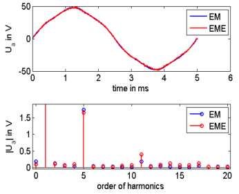
This paper presents an E-motor emulator with high power and current rating and excellent dynamic
characteristic. Chapter 2 deals with the need for a high dynamic emulator and the subsequent necessary
concept. Design and functionality of the emulator is described in chapter 3.Chapter 4 presents measurements
at a serial product. Conclusions are stated in chapter 5.

2. P-HIL Concept
A precise P-HIL emulation requires a complete identical behaviour at the terminals of the PHIL test bench
compared to the real machine. Therefore, the emulation converter has to apply a voltage at the coupling
network very precise and with a minimal dead-time to ensure the correct current slopes of arbitrary machines
within the coupling inductance. For this reason, the basic challenge of PHIL emulation is the calculation and
generation of this voltage. Modern FPGAs and A/D-converters allow the calculation of the machine model
including the counter voltage with sample rates of more than 3.125 MHz quasi continuous in real-time [3].
Indeed, the counter voltage generation is more challenging, especially for high power applications. The
counter voltages are discontinuous functions since the current slopes depend on the clocked output voltages
and are different in active as well as freewheeling states of the DUT. Moreover, the phase inductance of the
coupling network can not correspond to the differential inductances of the machine due to iron saturation or
the magnetic anisotropy of the rotor. For this reason, the emulation of the current slopes requires a converter
topology that allows a high dynamic and very precise generation of the counter voltages. The modular
multiphase converter and the associated modulation scheme offers such a dynamic and precise voltage
generation.

3. Design and functionality
The E-Motor Emulator is designed for inverters with
a DC-link voltage as high as 1000 V and phase
currents of 800 Arms. The emulator must have much
higher dynamics and significantly lower current
ripples compared to the device under test ( [4], [5],
[6]). Low switching frequencies and hence low
dynamics lead to very restricted emulation qualities
[7]. Therefore, the emulators switching frequency is
set to 800 kHz, the fundamental frequency of the
phase currents can reach up to 5 kHz. This Fig. 2: Topology of E-motor Emulator hardware.
functionality covers a broad range of applications, including high-speed drives with more than 100.000 rpm.
The model is calculated in 320 ns, which equates an update rate of 3.125 MHz. This powerful signal
processing unit enables detailed modeling of nonlinear motor characteristics. Furthermore, the model is able
to change its parameters dependent on the position of rotor, i.e. flux vs. angle can be modelled with additional
harmonics for instance.
The basic EME components are the multilevel inverter, coupling network at the output, current / voltage
measurement and high performance FPGA for calculation of the PMSM or ASM model (Fig. 2). Fig. 3 depicts
a typical PHIL test bench with unit under test, a battery emulator and the emulator itself with own DC-supply.
Both battery emulator and EME supply are galvanically isolated to achieve similar conditions as in the real
car, where the battery and the motor are floating against earth potential. The power flows in a circle, i.e. the
400 Vac mains must provide the entire power loss only (about 20% of the inverter’s output power). Due to
that, it is possible to test 430 kW inverters with a conventional 125A grid supply only.

EVS30 International Battery, Hybrid and Fuel Cell Electric Vehicle Symposium                     2
Test-Automation

                                                                                     Heat exchanger for EME
                                              HV +
                                                                E-Motor              water cooling (separated
                            Power Supply
                                              HV -
                                                                Emulator             from laboratory cooling
                                                                                     system)

     400 Vac
     Mains                                 Energy Cycle

                                              HV +
                               Battery                           Inverter            Conditioning of
                              Emulator        HV -
                                                             (Unit under Test)       water temperature

                                            Safety Control

                                    Fig. 3: Test setup with E-Motor Emulator.

4. Measurement results

The evaluation of the emulation quality of the phase currents is done through measurements with shorted
emulator outputs, i.e. there is no test inverter connected. This enables an objective quality evaluation with
lowest possible external influences. The phase currents are sampled and analysed through a Yokogawa power
analyser in combination with LEM Ultrastab IT-1000 current transducers. The phase currents at 1 kHz and 5
kHz are depicted in Fig. 4 and Fig. 5. The emulation quality is excellent, which prove the low THD results
in Fig. 6.
An alternative emulation technology from another emulator supplier uses a fixed PWM pattern for the power
semiconductors in the emulator’s amplifier. A variable DC-link voltage of the emulator enables the current
control at the emulator output. The THD and harmonics analysis shows that the presented control and
hardware concept offer a significantly better performance (Fig. 6, Fig. 7).

Fig. 4: Emulated phase current with 1,67 kHz fundamental Fig. 5: Emulated phase current with 5 kHz fundamental
frequency.                                                                    frequency.

EVS30 International Battery, Hybrid and Fuel Cell Electric Vehicle Symposium                        3
Other emulator supplier
Emulator of SET Power Systems
Other emulator supplier
Emulator of SET Power Systems
Fig. 7: Comparison of emulation quality by harmonic
Fig. 6: THD of emulated phase current vs. fundamental
analysis between a SPS and another emulator supplier
frequency.
(shorted emulator outputs, 104 Arms phase current with
1,67 kHz fundamental frequency).
The EME not only models the fundamental frequency and back-EMF, but emulates exactly the current ripples
depending on motor inductance and inverters switching frequency. Another quality criteria is the emulation
accuracy regarding the back-EMF, since the emulator is able to reproduce a back-EMF with non-linearities
and harmonics. Fig. 8 shows a comparison between measured back-EMF from an E-motor and emulated
back-EMF. The spectrum proves the high emulation accuracy.
Fig. 8: Comparison of measured and emulated non-linear back-EMF (picture taken from [1]).
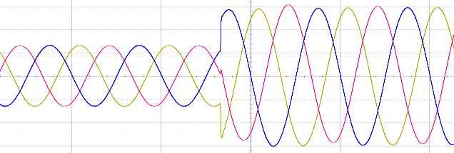
Fig. 9 depicts a high current motor start-up emulation. This occurs e.g. at the curbstone edge case, where the
car demands high torque at zero speed. An emulator enables the execution of this complicated test case in a
simple manner and under reproducible conditions and high freedom in parameterization. Furthermore, the
emulator allows the use of any load characteristics, independent from their complexity. The current and
frequency steps in Fig. 10 and Fig. 11 prove the high dynamic quality of the presented emulator.
EVS30 International Battery, Hybrid and Fuel Cell Electric Vehicle Symposium 4Fig. 9: Emulation of motor start-up from zero to 1 Hz with high currents (possible application: simulation of curbstone
edge case).
Fig. 10: Current step at 1 kHz fundamental frequency, which proves the high dynamic performance.
Fig. 11: Frequency step from 100 Hz to 1 kHz.
EVS30 International Battery, Hybrid and Fuel Cell Electric Vehicle Symposium 55. Conclusion
This paper presents a powerful E-motor emulator with high dynamic behaviour and high accuracy of output
voltage and phase current generation. This results in very precisely E-motor emulation with back-EMF, power
flow, current ripples and flux harmonics. The measurement results prove the high emulation quality, which
offers very low THDs in the range of 0.1 to 0,4% at fundamental frequencies up to 5 kHz. Furthermore, the
presented emulator technology copes with the requirements regarding emulation of three or six phase
permanent-magnet synchronous machines with nonlinear magnetics as well as asynchronous machines.
Main fields of application are development and end-of-line tests. It is possible to reuse mission profiles from
the design process in order to test the inverter and directly compare the simulated and real behaviour. The
EME has various advantages: no rotating parts, no maintenance, low safety requirements, high flexibility
regarding motor model parameters and emulation of fault scenarios or parameter tolerances. Furthermore,
some special test cases such as the curbstone edge case can be emulated in a very comfortable and
reproducible manner with high flexibility in parameterization. However, there is one important challenge:
the emulator needs motor parameters, which have to be acquired from FEM calculations or motor
measurements.
6. References
[1] S. Uebener and J. Böcker, "Application of an electric machine emulator for drive inverter tests within
the development of electric drives," EEVC Brussels, Belgium, pp. 19-22, November 2012.
[2] H. Hammerer and D. Strauss, "E-Maschinen-Emulator kontra rotierendem Prüfstand," ATZelektronik 7,
p. 192–197, 2012.
[3] A. Schmitt, J. Richter, U. Jurkewitz and M. Braun, “FPGA-based real-time simulation of nonlinear
permanent magnet synchronous machines for power hardware-in-the-loop emulation systems,” IECON
2014 - 40th Annual Conference of the IEEE Industrial Electronics Society, pp. 3763-3769, October 2014.
[4] S. Trabelsi, "Umrichterprüfung mit Hardware-in-the-Loop und Einsatz einer neuartigen schnellen
oberschwingungsarmen Leistungsendstufe," PHD thesis, ISSN 9783183364213, 2004.
[5] S. Grubic, B. Amlang and W. Schumacher, "A high-performance electronic hardware-in-the-loop drive
- Load simulation using a linear inverter," IEEE Transactions on Industrial Electronics, 57(4), pp. 1208
- 1216, December 2009.
[6] A. Schmitt, “Hochdynamische Power Hardware-in-the-Loop Emulation hochausgenutzter
Synchronmaschinen mit einem Modularen-Multiphasen-Multilevel Umrichter,” Disseration, 2017.
[7] M. F. Oettmeier, “Stator-Flux-Oriented control and real-time emulation techniques for permanent-
magent synchronous machines,” Dissertation, 2013.
[8] B. Cebulski and M. Thom, "Power-HiL-Simulation von Elektroantrieben für Hybridfahrzeuge,"
Internationaler ETG-Kongress, 2007.
EVS30 International Battery, Hybrid and Fuel Cell Electric Vehicle Symposium 67. Authors
Dr. Sebastian Liebig is responsible for several projects at SET Power Systems GmbH (SPS), which
is part of the AVL Group and a leading global supplier of inverter testing systems. Prior to joining
SPS, he worked for Liebherr-Elektronik as power electronics engineer and project manager. In
parallel, Sebastian worked at his PhD-thesis in the field of AC/DC topologies for aerospace
applications. For his work, he was granted in 2011 the best paper award of the international
conference PCIM in Nuremberg. Sebastian graduated 2014 at the Institute of Prof. Josef Lutz
(Technical University of Chemnitz, Germany).
Dr. Alexander Schmitt is responsible for system design at SET Power Systems GmbH (SPS), which
is part of the AVL Group and a leading global supplier of inverter testing systems. Prior to joining
SPS, Alexander worked at the Institute of Electrical Engineering (ETI) which is located at the
Karlsruhe Institute of Technology (KIT). He received his PhD degree from the KIT in 2017 for his
thesis about the high dynamic power hardware-in-the-loop emulation of nonlinear permanent
magnet synchronous machines with a modular multiphase multilevel converter.
Horst Hammerer is Co-Founder & CEO of SET Power Systems GmbH, part of the AVL Group and
a leading global supplier of inverter testing systems. He has been involved in aerospace, test systems
and power electronics for more than 30 years. Prior to founding his own company, Horst developed
and designed new testing strategies at Liebherr-Aerospace. In 2008 he was granted an innovation
award for successfully introducing a P-HiL component to test A380 CPCS computers, resulting in a
joint venture between his private enterprise and the AVL List GmbH. He is passionate about
enhancing and redefining testing methods for more meaningful results, focusing on the transfer of
aerospace testing methods to e-mobility. His visions and innovative approaches to technological
thinking make him a welcome speaker at conferences and universities. Horst studied in both
Germany and the UK and holds a degree in communication engineering from the University of
Applied Sciences Ulm.
EVS30 International Battery, Hybrid and Fuel Cell Electric Vehicle Symposium 7You can also read