Prism-Spectrometer as Demultiplexer for WDM over POF
←
→
Page content transcription
If your browser does not render page correctly, please read the page content below

Prism-Spectrometer as Demultiplexer for
               WDM over POF

                   Lutz, Daniela; Haupt, Matthias and Fischer, H.P., Ulrich

   Abstract—Polymer Optical Fibres (POFs) show                 they cannot be influenced by electromagnetic
clear advantages compared to copper and glass                  fields [1-4]. The wireless data communication
fibres (GOFs). In essence, POFs are inexpensive,               technology has two basic disadvantages
space-saving and not susceptible to electromagnetic            compared to fiber technology. First of all, the
interference. Thus, the usage of POFs has become a             electromagnetic fields can lead to interferences.
reasonable alternative in short distance data
communication. Today, POFs are used in a wide
                                                               Additionally, the radio technology is not secure
number of applications due to these specific                   from interference by third persons. As a result of
advantages. These applications include automotive              the mentioned features, POFs offer an attractive
communication systems and In-House-Networking.                 alternative.
The currently used transmission technology via POF                Nevertheless,    POFs      have    only     one
is based only on one channel (or rather on one                 transmission window, which is allocated in the
wavelength), making the usable bandwidth the limiting          visible spectrum of light. The attenuation of POF
factor of this technology. One potential solution to           is too high for the remaining electromagnetic
expand the usable bandwidth of POF-based systems               spectrum and therefore not acceptable for data
is wavelength division multiplexing (WDM). Because
of the attenuation behaviour of POF, the only
                                                               transfer.
transmission window is situated in the visible                    POFs are therefore best suited for the use in
spectrum. The solution proposed in this paper allows           short distance data communication. Today,
the transfer of several signals on different                   POFs are applied in in-house-networks and
wavelengths through a single polymeric fibre. In order         widely in the automotive industry [5]. It can thus
to separate the transmitted signals, special separators        be concluded, that POF technology is widely
– called demultiplexers (DEMUX) – are utilized.                applicable.
These DEMUX are realized by employing the
principle of the prism-spectrometer. In the set-up             1.2 WDM over POF
described in this paper, the light emitted by the                 The transmission with standard POF is
polymeric fibre is collimated via an off-axis parabolic        realised with only one wavelength [1-2]. The
mirror. Then it is led to a dispersion prism and there
divided into its monochromatic parts.
                                                               only possibility to increase the bandwidth is to
   Key words - WDM, POF, demultiplexer                         raise the data rate. This reduces the signal-to-
                                                               noise-ratio and can be changed therefore only in
                                                               strong limitations. In this paper, an established
               1. INTRODUCTION                                 technique for GOF technology is introduced and
1.1 Advantages and Applications of POF                         applied for POF. Though, it concerns the
  Polymer Optical Fibres offer essential                       wavelength multiplex technology. There are
advantages compared with GOF technology,                       different multiplex technologies available, e.g.
copper cable and wireless communication. In                    time division multiplex (TDM) [6]. Recently WDM
comparison to GOFs, POFs show a greater                        (wavelength division multiplex) and code division
mechanical      flexibility   making      them                 multiplex (CDM) have been used in GOF-
uncomplicated in handling because of the                       infrared    systems     and    in   mobile     RF
smaller bend radius.                                           communication [7-10]. The principle of WDM is
  Also, polymer optical fibres can be stressed                 transferred to the visible spectrum for POF
mechanically much stronger because of their                    communication,        which    means      several
geometrical dimensions. In comparison to                       wavelengths are used which are transmitted at
copper cables, which are still standard in                     the same time over one fibre. For more than 15
industry and technology, optical polymer fibres                years, WDM widely expanded the overall
save more space and weight. They allow an                      transmission bit rate in GOF-long-range
easy connector assembly as well. Additionally,                 systems, because of its easy expandable

                                                          25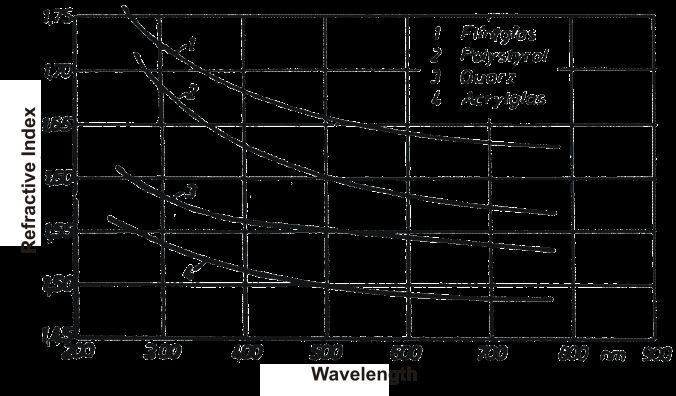
system approach: adding one new source with                aberrations of the dispersion prism, the beams
different transmission wavelength in combination           of light are leaded collimated. The prism
with a MUX/DEMUX-element expands the                       separates the light in its different wavelengths.
usable transmission rate directly by this source.          At the end of the DEMUX, a plano-convex lens
Due to the attenuation of POF, the wavelengths             focuses the separated wavelengths onto a
from 400nm to 700nm [1] are used for the WDM,              detection layer.
as shown in fig. 1.

    Fig. 1 Attenuation behaviour of a POF in
       the area of the visible spectrum

   For the use of WDM technology in POF-
systems, the same key elements are needed:
the multiplexer and the demultiplexer. A
complete redesign of these components is
necessary, because a different spectrum is
used. The light has to be combined by the
multiplexer and split by means of a
demultiplexer. This can be realised by means of
different techniques. An optical phased array
can be applied to change the phases of every
different channel and therefore to divide the light
in different channels [11]. Another possible
technique are interference filters, which are well-           Fig. 2 Setup of the demultiplexer and the
known in the infrared range but also available for           focus points at the detection layer in the
the visible spectrum [1, 12]. But key elements                              simulation
which are already available on the market use
the infrared wavelength range or are cost-
                                                              The setup uses only three colours, blue
intensive solutions and thereby not suitable for
                                                           (480nm), green (530nm) and red (660nm). This
mass market POF applications.
                                                           is not a limitation for possible future
                                                           developments, but rather an experimental basis
 2. BASIC CONCEPT OF THE MULTIPLEXER                       to run the various simulations described below.
   For WDM over POF, a complete new-
developed demultiplexer is required, as                       3. SIMULATION AND RESULTS OF THE
described in the previous chapter. The principle
                                                                                SIMULATION
of the demultiplexer is schematically illustrated
in fig. 2 and is already pending patent [13-15].             In the following step, a simulation program is
   A standard SI-POF with a core diameter of               used to design a demultiplexer based on the
980µm and a cladding thickness of 10µm is                  general concept outlined above. For the current
used. The refractive index of the core is about            task, the software OpTaliX provides all needed
the whole cross section equal 1.49 and the                 functionalities [16]. This approach offers different
numerical aperture is 0.5.                                 advantages, it is easy to design, analyze and
   The light emitted from the POF is focused and           evaluate the simulated results. Also effective
divided by the DEMUX. The POF is situated in               improvements of the configuration can be
the focus point of an off-axis parabolic mirror on         simulated fast. The simulated design was
which the light is reflected. To reduce the                planned and developed with available standard

                                                      26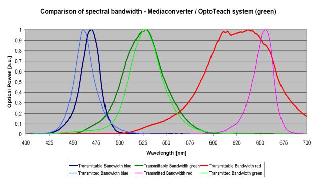
components.
   In the simulation of the DEMUX, all three
colours are detectable on the image layer, as
shown in fig. 2. The different focus points show
a diameter lower than 1mm. The cross talk is
below -30dB, because at the detection layer the
different channels do not overlap each other.

     4. LAB SETUP OF THE POF-DEMUX
4.1 Assembly
   To verify the simulation results, the DEMUX is
realised with commercially available standard
components under lab conditions. The
components are chosen, because they are
inexpensive and the geometrical dimensions are
close to the optimal design [17]. The complete
construction is shown in fig. 3.
   The various optical components effect the size
of the focus point in the image layer differently.
Especially the positioning of the POF and the
off-axis parabolic mirror have to be assembled
precisely, because a divergence of a few
micrometers in any direction affects the focus
size considerably at the detection layer. So for
both of these optical elements, micrometer
stages are used to guarantee a precise                        Fig. 4 Detection layer of the lab setup and
adjustment.                                                    measured intensity of the focus points

                                                            4.2 Characterisation of the DEMUX-Setup
                                                               In the first step, a characterisation of the lab
                                                            setup is demonstrated for the attenuation
                                                            behaviour and channel bandwidth. For the
                                                            measurement of the general attenuation of the
                                                            DEMUX, the colours blue, green and red will be
                                                            transferred without multiplexing. For the
                                                            channels blue and red media converters from
                                                            DieMount [18] and for the green channel the
                                                            OPTOTEACH teaching system of HarzOptics
                                                            [19] are used.
                                                               Furthermore,       a   white     light    source
                                                            (YOKOGAWA AQ 4305) is used for the
                                                            estimation of the available bandwidth for every
 Fig. 3 Lab setup including the path of rays                channel, see fig. 5.

   A separation without viewable overlap of the
three channels is achieved with an optimal
alignment of the optical elements and a
concurrent transfer of the wavelengths over POF                Fig. 5 Schematic setup with white light
used for this lab setup. The intensity dispersion                             source
is shown in fig. 4. It is demonstrated, that a clear
separation of the different channels is achieved.             A connection is built up with all three WDM-
However, the spectral width of the different                channels (470nm, 520nm, 650nm), see fig 6.
channels avoids a clear determination.

                                                       27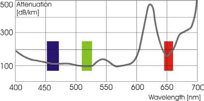
Fig. 6 Schematic setup for 3 channel
               attenuation measurement

     The attenuation caused through the data
  transfer by the system is at blue 19,3dB, at
  green 12,1dB and at red 14dB. A coupler of the
  company HarzOptics for the combination of two
  channels causes an additional attenuation of
  about 5-6dB, see table 1. Fig. 7 demonstrates
  the existing cross talk of the different channels.
     By means of a white light source, the
  spectrum is measured to verify the received
  signals and to estimate the channel bandwidth,
  as shown in fig. 7. The cross talk between the
  blue channel and the green channel is 4,6dB
  respectively 16,1dB. Also, the cross talk of the
  green channel to the red channel is rather high
                                                                          Fig. 7 Cross-talk of the 3 channels and
  with 13,3dB. It can be recognised, that the
                                                                                 comparison of the spectra
  spectral width of the red channel is larger in
  comparison to the blue channel. An explanation
  can be found in fig. 8, the steeper the curve falls
  the larger the gap between the colours.

Optical component \
                             λ = 470nm   λ = 520nm   λ = 650nm
Channel
Attenuation DEMUX
                               19,3        12,1         14
(1 channel) [dB]
Attenuation DEMUX
(with coupler & connector)     23,9        18,9        19,8
[dB]
         TABLE 1. ATTENUATION RESULTS OF THE
                        DEMULTIPLEXER
                                                                         Fig. 8 Refractive index in dependence of
                                                                                         wavelength
                                                                         Therefore, the dispersion of the prism is non-
                                                                      linear. Furthermore the attenuation trait is also to
                                                                      view for short POF-lengths. This can be seen in
                                                                      the curve progression of the red channel. It
                                                                      shows an easy reduction of the signal power
                                                                      located for the wavelength area about 620nm,
                                                                      shown in fig. 1.

                                                                      4.3 Data Transfer
                                                                         The first Fast Ethernet data transfer was
                                                                      designed and tested with the colours red and
                                                                      blue, see fig. 9. An error-free transfer of data
                                                                      was realised. For the Ethernet data transfer the
                                                                      DEMUX behaves transparent. The functionality
                                                                      of the WDM-system is thus verified.

                                                                 28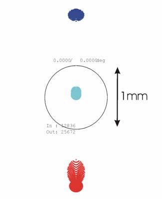
REFERENCES
                                                           [1]    W. Daum, J. Krauser, P. E. Zamzow, O. Ziemann, „
                                                                  POF Handbook: Optical Short Range Transmission
  Fig. 9 Schematic setup Ethernet data link                       Systems “, Springer-Verlag, 2008
                                                           [2]    H. S. Nalwa (Ed.), “Polymer Optical Fibers”, American
   However, because of the attenuation, which is                  Scientific Publishers, California 2004Last name1, Fn1.,
                                                                  Last name2, Fn2., “Paper title,” http://www.(URL), Day.
still too high, the data transfer is possible with                Month. Year, pp. 15–64.
only one channel. For a data transfer via WDM,             [3]    Club des Fibres Optiques Plastiques (CFOP) France,
the transmitted signals are too weak considering                  “Plastic Optical Fibres – Practical Applications”, Edited
their appearing attenuation. With the media                       by J. Marcou, John Wiley & Sons, Masson, 1997
                                                           [4]    J. Brandrup, E. H. Immergut, E. A. Grulke, “Polymer
converters used in combination with couplers, a                   Handbook” 4th Edition, Wiley-Interscience, 1999…
combined signal transfer is currently not                  [5]    http://www.mostcooperation.com/
possible, but it may become possible with a                [6]    E.       Voges,       K.      Petermann,        „Optische
more precise adjustment of the focus length.                      Kommunikationstechnik“, Springer-Verlag, 2002
                                                           [7]    R. T. Chen and G. F. Lipscomb, Eds, “WDM and
                                                                  Photonic Switching Devices for Network Applications”,
                                                                  Proceedings of SPIE, vol. 3949, 2000
4.4 Conclusion and Outlook                                 [8]    J. Colachino, “Mux/DeMux Optical Specifications and
   This paper demonstrates, that it is principally                Measurements”,       Lightchip     Inc.   white    paper,
                                                                  Lightreading, July 2001Remember that each paper
possible to design and use a demultiplexer for                    must have at least 10 references!
polymer optical fibres and also to separate the            [9]    A. H. Gnauck, A. R. Chraplyvy, R. W. Tkach, J. L.
different channels.                                               Zyskind, J. W. Sulhoff, A.J. Lucero, et. al., “One
   The adjustment of the optical components                       terabit/s transmission experiment”, in Proc. OFC’96, PD
                                                                  20, San Jose, CA, 1996
used in the lab setup exhibits a very high                 [10]   C. R. Batchellor, B. T. Debney, A. M. Thorley, T. J. B.
attenuation of the transmission link.                             Swanenburg, G. Heydt, F. Auracher,et. al., “A coherent
   At the moment, it is only possible to transmit                 multichannel demonstrator”, Electr. & Comm. Engineer.
signals with high optical power to receive and                    J., 235- 242 (1992)J. Brandrup, E. H. Immergut, E. A.
                                                                  Grulke, “Polymer Handbook” 4th Edition, Wiley-
use the transmitted signals with sufficient optical               Interscience, 1999…
power at the end of the transfer distance,                 [11]   U. H. P. Fischer, “Optoelectronic Packaging”, Vde-
because of the high appearing attenuation. The                    Verlag, 2002
focused signals at the detection layer are                 [12]   Fraunhofer Institut für Integrierte Schaltungen, “Optical
                                                                  multiplexer     for   short     range    communication”
separated clearly as such and are detectable in                   http://www.iis.fraunhofer.de/ec/oc/download/demux.pdf
comparison to the simulated spot diagram.                  [13]   Multiplex-Sender für Polymerfaserübertragung und
   We still believe, that WDM over POF has a                      Verfahren zu dessen Herstellung, 10 2005 050 747.6
good potential to substitute the classical transfer               (Tx) 22.10.2005
                                                           [14]   Demultiplex-Empfänger für Polymerfaserübertragung
technology in many areas of the short distance                    und Verfahren zu dessen Herstellung, 10 2005 050
communication. But it is necessary to                             739.5 (Rx), 22.10.2005
manufacture special components for this setup              [15]   Multiplex-Transceiver für Polymerfaserübertragung und
to increase the gaps between the channels. With                   Verfahren zu dessen Herstellung, 10 2006 009 365.8
                                                                  (Trx)
standard components, an online three channel               [16]   http://www.optenso.com
data communication assembly was not possible.              [17]   U. H. P. Fischer, M. Haupt “WDM over POF – The
   To make the WDM over POF solution                              inexpensive way to breakthrough the limitation of
attractive for the mass market, a possible                        bandwidth of standard POF communication” SPIE
                                                                  Photonics West 2007, San Jose, USA
inexpensive production must be implemented                 [18]   http://www.diemount.de
with improved components. One possible                     [19]   http://www.harzoptics.de
solution would be the moulding technology,
which is a low-cost production with high amount
of pieces.

                                                      29
You can also read