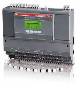
Arc Guard SystemTM - TVOC-2
←
→
Page content transcription
If your browser does not render page correctly, please read the page content below
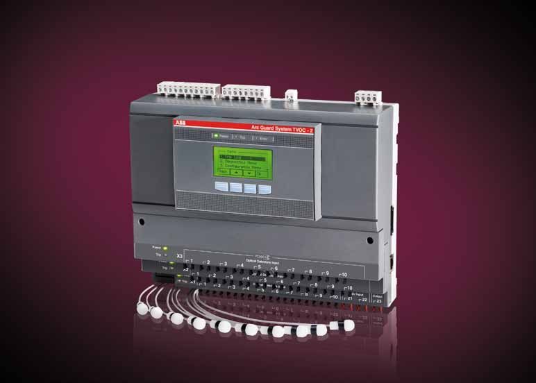
Catalog

Arc Guard SystemTM – TVOC-2
Introduction

An even better Arc Guard System™                                         Reliability
TVOC-2, ABB’s latest Arc Monitor, builds on the well known               Certified according to functional safety (SIL-2) standard
TVOC design. Its new functions and features improve an                   Over 35 years experience in Arc Guard Systems
already great product, putting even more focus on reliability,           Pre-calibrated optical sensors
flexibility and simplicity.                                              Flexibility
                                                                         HMI (Human Machine Interface) can be mounted
Arc Guard System™ protects people and equipment, and eli-
                                                                         on the panel door
minates unnecessary production stops.
                                                                         Expand with up to 30 optical sensors
Arc monitor type TVOC-2 is ABB’s state-of-the-art solution for           Configure the system according to various needs
arc fault protection in all applications, providing functional safety.   Simplicity
With over 35 years of experience, Arc Guard System™ has                  User-friendly start-up menu
become an industry standard in several key markets, helping to           DIN-rail or wall-mounted
protect personnel and businesses around the world.                       Easy to expand as the switchgear grows
Typical applications include all low- and medium-voltage switch-
gears.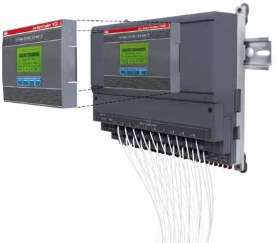
Contents

           Contents:
           Introduction .............................................................................................................. 2
           Contents ................................................................................................................... 3
           System description .................................................................................................. 4
           Functionality.............................................................................................................. 5
           Order details ............................................................................................................. 6
           Technical data ......................................................................................................... 8
           Applications............................................................................................................. 10
           Configuration .......................................................................................................... 12
           Dimensions.............................................................................................................. 14
           Diagrams.................................................................................................................. 15

                                                                1SFC170001C0201 | Arc Guard SystemTM TVOC-2 Catalog 3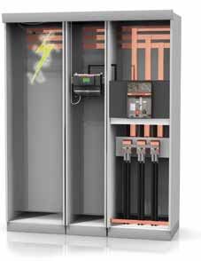
System description

Arc Guard System™
Arc Guard System™ quickly detects an arc fault and trip the incoming circuit-breaker. Using light as the main condition, Arc Guard Sys-
tem™ trips instantaneously. Thanks to this key functional advantage, it overrides all other protections and delays, which is crucial when
reaction times need to be measured in milliseconds.

How it works
The system acts in three phases:
 1                                              2                                                 3
• Light pases through an optical sensor        • The Arc monitor determines the                  • Sends signal to trip breaker(s)
  (Detection)                                    intensity of light (Recognition)                  (Action)

                                                                                    Arc Faults
                                                                                    Short-circuit faults in LV and MV switchgears are often
                                                                                    accompanied by an electric arc. An arc fault always
                                                                                    leads to considerable damage to equipment and injury
                                                                                    to personnel unless it is detected very quickly. To avoid
                                                                                    serious damage and give the person involved a good
                                                                                    chance of surviving the accident without severe injury,
                                                                                    the fault should be disconnected as fast as possible,
                                                                                    typically in less than 30-50 ms.

Total breaking time = ABB ArcGuard System™ + Breaker

4 Arc Guard SystemTM TVOC-2 Catalog | 1SFC170001C0201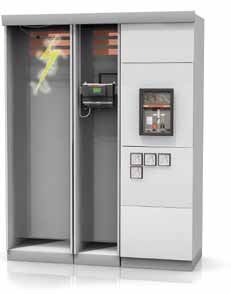
Functionality

Arc Monitor                                                                               HMI (Human Machine Interface)
With its modular concept, the Arc Monitor is designed to fit all                          • Handles settings with key-pad and full text display.
types and sizes of low- and medium-voltage switchgears.                                   • Holds error log and trip information after power loss.
It is designed according to Functional Safety, and is SIL 2-                              • Error log and trip log include time/date stamp from a
certified according to IEC 61508 and IEC 62061 which puts                                   real-time clock.
full focus on reliability. This corresponds to performance level                          • TVOC-2 can handle two separate HMI:s (cabinet door
d according to EN ISO 13849-1. Safety functions are exclu-                                  and on product).
sively handled by hardware. In addition, the system, trip logs                            • Three-meter cable included.
and user-interface are all microprocessor-monitored.
                                                                                          Sensor & Sensor modules
The system can be configured to trip selected breakers, depen-                            • Fibre-optic sensors not affected by electrical noise
ding on which sensor detects light. The dip-switches that take                            • Pre-calibrated sensors remove need for manual configuration
care of this function also handle settings like auto-reset and Cur-
                                                                                          • Up to 30 detectors can be connected
rent Sensing Units (see pages 12-13 for more details).

Energy is stored in the unit for operation up to 0.2 s if the supply                      Current Sensing Unit (optional)
voltage fails. This is sufficient to close the tripping circuit even if                   The Current Sensing Unit is an accessory needed only in those
voltage disappears at a short-circuit fault.                                              few specific applications where strong light is expected on a
Note: The circuit breaker still needs a back-up energy source for its tripping circuit.   regular basis.
                                                                                          Current sensing units (CSUs) are connected with an optical fibre
Connections                                                                               using light as signal for normal current. If this was removed by
All connections can be accessed from the front of the arc monitor.                        accident, the system would treat it as an over-current and trip if an
Pluggable terminal blocks allow electrical wiring before mounting                         arc flash is seen of reliability reasons.
TVOC-2 into the cabinet.
The solid state tripping contacts are type IGBT, which guarantees
fast and reliable tripping.
More details can be found on page 8, technical data.

                                                                                                  Arc Monitor connections
                                                                                                  3 IGBT solid state tripping contacts
                                                                                                  2 change-over trip signal relays
                                                                                                  1 change-over self supervision alarm relay
                                                                                                  2 current sensing unit inputs
                                                                                                  1 current sensing unit output

                                                                                                  Mounting alternatives
                                                                                                  DIN-rail
                                                                                                  Wall mounting

                                                                                                  Optical detector inputs
                                                                                                  1-10 Main unit X1
                                                                                                  1-10 Extension module X2
                                                                                                  1-10 Extension module X3

                                                                                                  HMI
                                                                                                  Can be mounted on door
                                                                                                  IP 54
                                                                                                  Additional HMI possible
                                                                                                  User-friendly start up meny

                                                                                                        1SFC170001C0201 | Arc Guard SystemTM TVOC-2 Catalog 5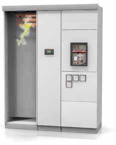
Ordering details

                                   Supply voltage 100-240 V DC or AC 50-60 Hz
                                                                                                           Weight
                                   Description                           Type          Order code              kg
                                   Arc Monitor                           TVOC-2-240    1SFA664 001 R1001     0.95
                                   including one HMI and door mounting
                                   accessories
                                   Extension                             TVOC-2-E1     1SFA664 002 R1001     0.15
                                   10 optical inputs
                                   Extension                             TVOC-2-E3     1SFA664 002 R3001     0.15
                                   10 optical inputs for 60 meter
                                   detector cable
        Arc Monitor                HMI (Human machine interface)         TVOC-2-H1     1SFA664 002 R1005     0.15
                                   additional

                                   Detectors
                                   Cable length             1m           TVOC-2-DP1    1SFA664 003 R1010     0.02
                                   Cable length             2m           TVOC-2-DP2    1SFA664 003 R1020     0.02
        Extension unit             Cable length             4m           TVOC-2-DP4    1SFA664 003 R1040     0.04
                                   Cable length             6m           TVOC-2-DP6    1SFA664 003 R1060     0.60
                                   Cable length             8m           TVOC-2-DP8    1SFA664 003 R1080     0.80
                                   Cable length             10 m         TVOC-2-DP10   1SFA664 003 R1100     0.10
                                   Cable length             15 m         TVOC-2-DP15   1SFA664 003 R1150     0.15
              HMI
                                   Cable length             20 m         TVOC-2-DP20   1SFA664 003 R1200     0.20
                                   Cable length             25 m         TVOC-2-DP25   1SFA664 003 R1250     0.25
                                   Cable length             30 m         TVOC-2-DP30   1SFA664 003 R1300     0.30
                                   Cable length   3)
                                                            60 m         TVOC-2-DP60   1SFA664 003 R3600     0.60
        Detector cable
                                   Remarks:
                                   3) Only to be used with TVOC-2-E3

6 Arc Guard SystemTM TVOC-2 Catalog | 1SFC170001C0201
Ordering details
Weight
Description Type Order code kg
Current sensing unit CSU 1SFA 663 002-A 1.50
Optical cable between TVOC-2 Arc monitor and Current sensing unit
Cable length 0.5 m TVOC-1TO2-OP05 1SFA664004R2005 0.01
Cable length 1m TVOC-1TO2-OP1 1SFA664004R2010 0.01
Cable length 2m TVOC-1TO2-OP2 1SFA664004R2020 0.02
Cable length 4m TVOC-1TO2-OP4 1SFA664004R2040 0.04
Cable length 6m TVOC-1TO2-OP6 1SFA664004R2060 0.06
Cable length 8m TVOC-1TO2-OP8 1SFA664004R2080 0.08
Cable length 10 m TVOC-1TO2-OP10 1SFA664004R2100 0.10
CSU
Cable length 15 m TVOC-1TO2-OP15 1SFA664004R2150 0.15
Cable length 20 m TVOC-1TO2-OP20 1SFA664004R2200 0.20
Cable length 25 m TVOC-1TO2-OP25 1SFA664004R2250 0.25
Cable length 30 m TVOC-1TO2-OP30 1SFA664004R2300 0.30
Optical cable TVOC-2 – CSU
Optical cable between two TVOC-2 – Arc monitors (transfering CSU signal)
Cable length 0.5 m TVOC-2_OP05 1SFA664 004 R1005 0.01
Cable length 1m TVOC-2-OP1 1SFA664 004 R1010 0.01
Optical cable TVOC-2 – TVOC-2
Cable length 2m TVOC-2-OP2 1SFA664 004 R1020 0.02
Cable length 4m TVOC-2-OP4 1SFA664 004 R1040 0.04
Cable length 6m TVOC-2-OP6 1SFA664 004 R1060 0.06
Cable length 8m TVOC-2-OP8 1SFA664 004 R1080 0.08
Cable length 10 m TVOC-2-OP10 1SFA664 004 R1100 0.10
Cable strap Cable length 15 m TVOC-2-OP15 1SFA664 004 R1150 0.15
Cable length 20 m TVOC-2-OP20 1SFA664 004 R1200 0.20
Cable length 25 m TVOC-2-OP25 1SFA664 004 R1250 0.25
Cable length 30 m TVOC-2-OP30 1SFA664 004 R1300 0.30
Mounting kit
Cable straps 1 set incl. 50 pcs TVOC-2-MK1 1SFA664 006 R1001 0.10
Mounting kit 600 mm 1SFA663 006 R1001 0.35
800/1000 mm 1SFA663 006 R1002 0.60
Label
Label 1 set incl.10 pcs 1SFA663 005 R1001 0.02
Mounting bracket 1 set incl. 5 bracket 1SFA663 006 R1010 0.25
pcs and 10 cable
strap pcs
Mounting bracket
1SFC170001C0201 | Arc Guard SystemTM TVOC-2 Catalog 7Technical data
Optical inputs and output
Optical detectors 10 inputs on Arc Monitor
10 inputs on Extension unit X2 (optional)
10 inputs on Extension unit X3 (optional)
Current signal from CSU 2 inputs: X1.21, X1.22 (optical)
Forward current signal to another Arc Monitor 1 output: X1.23 (optical)
Breaker trip contacts (K4, K5, K6)
Solid state tripping contacts 3 NO solid state type IGBT
Rated voltage 250 V AC/DC
Make and carry for 0.2 s 30 A
Make and carry for 1 s 0.15% duty ration 10 A
Breaking capacity 250 V 1.5 A AC-15
250 V 1A DC-13
110 V 3A DC-13
48 V 3A DC13
Reinforced insulation between separate contacts
Voltage drop 5 V 30 A, 3 V 3 A, 2 V 10 mA
Off state current < 1 mA at 250 V 60 Hz
Min. recommended load current 10 mA
Signal relay outputs (K2, K3)
Manual or auto resetable 2 CO gold-plated contacts
Rated voltage 250 V AC/DC
Continous carry Ith 5A
Make and carry for 0.2 s 30 A
Make and carry for 3 s 10% duty ratio 15 A
Breaking capacity 250 V 3A AC-15
250 V 0.3 A DC-13
110 V 0.6 A DC-13
48 V 2A DC-13
Reinforced insulation between separate contacts
Ith = 5 A
Min switching load:
1 mA at 5 V DC with contacts not used for switching current
> 0.5 A if inductive/capacitive load before.
Internal Relay Fault (IRF) signal (K1)
Self supervision alarm relay 1 CO gold-plated contact
Rated voltage 250 V AC/DC
Continuous carry, Ith 5A
Make and carry for 3 s 8A
Breaking capacity 250 V 1.5 A AC-15
250 V 0.15 A DC-13
110 V 0.3 A DC-13
48 V 0.5 A DC-13
Reinforced insulation between separate contacts
Ith = 5 A
Min switching load:
1 mA at 5 V DC with contacts not used for switching current
> 0.5 A if inductive/capacitive load before
8 Arc Guard SystemTM TVOC-2 Catalog | 1SFC170001C0201Technical data
Settings and indications
Connections for HMI on base module 1 output RJ45 male at front side
1 output RJ14 female at right side
Display on HMI 52 x 26 mm graphic LCD with LED backlight
Keyboard on HMI Membrane buttons, 4 soft keys
LED signal on HMI Power, Trip, Error
LED signal on Arc Monitor and extension units Power, Trip
Configuration switches 8-pole DIP-switch on Arc Monitor front
Settings (HMI) Time and display language
Configuration (DIP switches) Manual or auto reset of K2 and K3
Use of CSU or not
Trip configuration
Display information Trip log, connected modules, actual configuration
self diagnostic test result and error log
Power supply
Rated supply voltage, Us 100-240 V AC, 50-60 Hz
100-250 V DC
U s variation AC -20% – +10%
DC -25% – +30%
Rated insulation voltage, U i 250 V with reinforced insulation
Rated impulse withstand Voltage Uimp 4 kV
Main MCB/fuse Max. 10 A char. C/fuse 10 A gG
Power consumption 5W
Reaction time
From light detection to trip (contacts K4, K5, K6) Approx. 1 ms (depends on light intensity)
From light detection to indication signal (relay K2, K3) < 10 ms
Current condition from input to output < 0.4 ms
Start-up time
Trip possible < 15 ms from power on
Altitude 2000 m above sea level
Permissible ambient temperature -25 to +55°C
Degree of protection IP20 Arc Monitor
IP54 HMI front side
Detector cable
Maximum length 30 m with Arc Monitor and extension – E1
60 m with extension – E3
Service temperature range -25 to +70°C continuous
-25 to +85°C short-time
Smallest permissible bending radius 45 mm after installation
10 mm on handling
Acceptable backlight intensity light without tripping 3000 Lux
Optical cable
Maximum length 30 m
1SFC170001C0201 | Arc Guard SystemTM TVOC-2 Catalog 9Applications
Basic installation tips
Arc Monitor (TVOC-2)
The Arc Monitor can be mounted anywhere in the switchgear, e.g.
in the breaker cubicle or in a separate control cabinet. Tripping is Q1
handled by a separate tripping circuit. The task of the Arc Monitor is F11 A1
to close the circuit very quickly. You can connect up to 3 breakers in
D
this way and, if required, trip different breakers depending on where
the arc occurs. Arc Guard System with Arc Monitor A1 Switchgear
F11 Arc Monitor
F21 Current Sensing Unit
CSU (Current Sensing Unit) T1 Current transformer
The CSU is an accessory used if you cannot prevent direct sunlight Q1 Circuit-breaker
or other highly intensive light reaching the sensors frequently. CSUs F21 T1
can be mounted in series if more than two are needed.
Q1
Connection of current transformers (for CSU)
F11 A1
The CSU measures either 1, 2 or 3-phase. Three-phase is, however,
preferable for reasons of safety and reliability. Current transformers
with a secondary current of 1, 2 or 5 A are used for this purpose.
Arc Guard System with Arc Monitor and Current Sensing Unit
Note: Current transformers for relay protection are preferable since they do not satu-
rate as quickly as standard current transformers. The transformers should not saturate
before at least twice the set over-current level.
Detectors
Detector cables are available in standard lengths (see ordering de-
tails). They cannot be cut or joined. Avoid sharp bends or pinching
when installing the cables.
The plastic fiber is made of polymethylene acrylate (PMMA) with a
PVC jacket . Each detector consists of an optical cable and a lens
Polar diagram of detector
that are calibrated together to give the same sensitivity independent
of cable length. The detector has a plug-in connector that fits the arc
monitor. The lens collects light from all directions, with the exception
of a small shaded area behind the detector (see the polar diagram).
Practical experiments have shown that arc light reflected between
metallic surfaces is normally sufficient to cause tripping.
Detector positioning
The basic strategy for positioning the sensors is to make sure that
you cover all parts that may suffer from an arc. Typically this involves
the horizontal and vertical bus bar system and the breaker cubicle. If
possible, it’s also normally preferable to supervise each cubicle. Avoid
placing the detector so that it sees the normal light from a breaker.
The sensor can detect arcs within a 3-meter distance (see illustration
above). To raise the safety level even higher, you can separate them
at a 1.5-meter distance, thereby creating redundancy between them.
Example showing the position of detectors in:
1. Horizontal and vertical bus bar system
2. Circuit-breaker cubicle
10 Arc Guard SystemTM TVOC-2 Catalog | 1SFC170001C0201Applications
Diagrams
Example 1:
Arc Guard SystemTM installed to trip all breakers in case of an arc.
SA1... SA3 Switchgear
K4, K5 Solid state trip-
ping contacts
Q1, Q2, Q3 Circuit-breaker
D1...D4 Detectors
Example 2:
Arc Guard SystemTM installed to trip different breaker depending on
where the arc occurs.
SA1... SA4 Switchgear
K4, K5, K6 Solid state trip-
ping contacts
Q1, Q2 Circuit breaker
Q3 Bus couplar
D1...D9 Detectors
1SFC170001C0201 | Arc Guard SystemTM TVOC-2 Catalog 11Configuration
Trip condition configuration – Manual/auto reset configuration
Trip condition configuration
TVOC-2 can be configured to trip selected breakers depending on detector or CSU signal.
See below for instruction
Trip signals (All detectors operates K2, K3)
Signal relay K2 Signal relay K3
Sw3 Sw4 Function detectors
0 0 Any detection trips all
breakers K4, K5, K6
0 1 Detectors X1 operate K4
Detectors X2 operate K5
Detectors X3 operate K6
1 0 Detectors X1:1-3 operate K4
Detectors X1:4-6 operate K5
Detectors X1:7-10, X2 and X3
operate K6
1 1 Any detector + current condi-
tion CSU21 operate K4 + K5
Any detector + current condi-
tion CSU22 operates K5 + K6
Manual/auto reset configuration
The signal relays K2, K3 can be configurate to react as the trip contacts (auto reset) or to be de-energized
by manual reset on the HMI. See below for explanation.
12 Arc Guard SystemTM TVOC-2 Catalog | 1SFC170001C0201Configuration
Current condition configuration
System configuration using DIP switch
DIP switches are used to configure the system regarding use of current condition (activated CSU inputs) assigning
detectors to breaker trip outputs (so-called selectivity) They are located on the front (low, left) of the arc monitor.
DIP switches
Sw1 Current condition inputs Terminals X1:21-22 Sw5 Not used
Sw2 Current condition output Terminal X1:23 Sw6 Autoreset K2, K3
Sw2 Trip output assign Sw7 Not used
Sw4 Trip output assign Sw8 Not used
Sw1 Sw2 Function
Current condition
0 0 Not used
1 0 Input CSU21 used
Breaker trip contacts Detector inputs
Output relay K4 Terminals X1:1-10
1 1 Both inputs used
Output relay K5 Terminals X2:1-10
Output relay K6 Terminals X3:1-10
1SFC170001C0201 | Arc Guard SystemTM TVOC-2 Catalog 13Dimensions
Arc Monitor HMI
For M5 217
187,5
Detector with optical cable
Current Sensing Unit
A flange with 6 tapped holes
(size 18.6 mm), 4 cable glands
(sealing diameter 5.5-8.5 mm),
and 2 plastic blank plugs are
supplied.
14 Arc Guard SystemTM TVOC-2 Catalog | 1SFC170001C0201Circuit diagrams
Arc Monitor
Terminals
I>
X1 1-10 Detector input
X1. X2 1-10 Extra detector unit detector input
IGBT K6 Trip
63
64
23 (option)
B
53 A
22
X3 1-10 Extra detector unit detector input
IGBT K5 Trip 21
54 (option)
43 10
IGBT K4 Trip
44
Trip
&
9
A1, A2 Power supply
31 8 PE Power supply
Relay K3 Trip 34
7
32
6
43, 44 Solid-state contacts
21
IRF
Relay K2 Trip 24
22
5 1-10 53, 54 Solid-state contacts
U>0 4
11
Relay K1 Trip 14 3
63, 64 Solid-state contacts
12 2 11, 12, 14 Indication contacts
1
21, 22, 24 Indication contacts
74 X2.
10
73
9
31, 32, 34 Indication contacts
8
7
6
5 1-10
4
3
2
1
10 X3.
9
8
7
6
5 1-10
4
3
2
1
PE A1 A2
N L1
Current Sensing Unit Terminals
1 ... 6 Current transformer terminals
7 ... 8 Output current signal to another
Current Sensing Unit or Arc Monitor
9 Input current signal from another
Current Sensing Unit
Power supply terminals
10 and 12 24 V DC
11 and 12 60 V DC
11 and 12 48 V DC Interconnection 11-13
13 and 12 110 V - 125 V AC/DC
14 and 12 220 V DC, 230 V AC
A) Testing facilities:
R29 Simulating a test current
S1 1 = Test position
2 = Operation position
V22 Red ON = S1 in test position
OFF = S1 in operation position
B) Setting facilities:
R21 Overcurrent setting
S2 1 = Input 9 not used
2 = Input 9 used
V27 Yellow ON = Load current less than
70% of set overcurrent level
OFF = Load current more than
70% of overcurrent level
V29 Green ON = Load current less than
set overcurrent level
OFF = Load current more than
set overcurrent level
X) Current range bridge connections
1A: 24-17, 25-20, 26-23
2A: 24-16, 25-19, 26-22
5A: 24-15, 25-18, 26-21
1SFC170001C0201 | Arc Guard SystemTM TVOC-2 Catalog 15Contact us
ABB AB ©Copyright 2010, All rights reserved.
Catalog 1SFC170001C0201, March 2010 Prod ABB AB, Cewe-Control/XM
Cewe-Control Specification subject to changes without notice.
SE-721 61 VÄSTERÅS, Sweden
Telephone +46 21 32 07 00
Telefax +46 21 12 60 01
www.abb.com/lowvoltageYou can also read