BOSS ROOM-MATE 3T - THROUGH THE TRAP METHOD - USER GUIDE
←
→
Page content transcription
If your browser does not render page correctly, please read the page content below
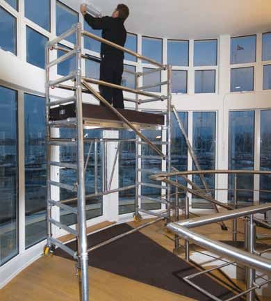
BoSS Room-Mate
                    3T - Through the Trap Method

User Guide
  Edition 2: 2010
Safety First
Mobile Towers - 3T Method
INTRODUCTION
Please read this guide carefully.
Please note that diagrams are for illustrative purposes only.
User guides are also available to download from our website
at youngmangroup.com
BoSS mobile aluminium towers are light-weight scaffold
towers used throughout the building and construction
industry for both indoor and outdoor access solutions
where a stable and secure platform is required. Ideal for
maintenance and installation work or short-term access, the
highly versatile towers provide a strong working platform for
a variety of heights.
This User Guide provides you with step by step instructions
to ensure your system is erected easily and safely, using the
3T (Through The Trapdoor) method.
The law requires that personnel erecting, dismantling or
altering towers must be competent. Any person erecting
a Youngman BoSS mobile tower must have a copy of this
guide. For further information on the use of mobile access
and working towers consult the PASMA operators code of
practice.
If you need further information, design advice, additional
guides or any other help with this product, please contact
Youngman on +44 (0)1621 745900
or email sales@youngmangroup.com
COMPLIANCES
Following examination by the SP
Technical Research Institute of
Sweden, the Boss Room – Mate
mobile access tower has been
issued with a Type Examination
Certificate No 249403 in accordance
with the requirements of Ordinance
AFS 1990:12 Stallningar, type
examination rules SPCR 064 for
temporary structures and SS-EN
1004:2005 including appurtenant Instruction Manual
standards. EN 1298-IM-EN
1 BoSS Room-Mate User GuideSafety First PREPARATION AND INSPECTION Inspect the equipment before use to ensure that it is not damaged and that it functions properly. Damaged or incorrect components shall not be used. SAFE USE Check that all components are on site, undamaged and that they are functioning correctly – (refer to Checklist and Quantity Schedules). Damaged or incorrect components shall not be used. Check if the ground on which the mobile access tower is to be erected and moved is capable of supporting the tower. The safe working load is 275 kgs (606lbs), per platform level, uniformly distributed up to a maximum of 750kgs, per tower. Towers must always be climbed from the inside during assembly and use. It is recommended that towers should be tied to a solid structure when left unattended. Adjustable legs should only be used for levelling. LIFTING OF EQUIPMENT Tower components should be lifted using a reliable lifting material (e.g. strong rope), employing a reliable knot (e.g. clove hitch), to ensure safe fastening and always lift within the footprint of the tower. Assembled mobile towers should not be lifted with a crane or other lifting device. Safety First Safety First. youngmangroup.com 2
Safety First
    STABILISERS / BALLAST

     Stabilisers or outriggers and ballast weights shall always
     be fitted when specified.

     The Quantity Schedules show the recommended
     stabilisation. In circumstances where there is restricted
     ground clearance for stabilisers/outriggers, contact your
     supplier for advice. Ballast must be of solid materials (i.e.
     not water or loose sand) and should not be positioned
     to overload individual legs. Ballast should be secured
     against accidental removal where practicable, and be
     supported on the lowest rung of the bottom frame.

    MOVEMENT

     The tower should only be moved by manual effort, and
     only from the base.

     When moving the tower, beware of live electrical
     apparatus, particularly overhead, plus wires or moving
     parts of machinery.

     No person or materials should be on the tower during
     movement.

     Caution should be exercised when wheeling a tower over
     rough, uneven or sloping ground, taking care to unlock
     and lock castors. If stabilisers are fitted, they should only
     be lifted a maximum of 25mm above the ground to clear
     ground obstructions.

     The overall height of the tower when being moved, should
     not exceed 2.5 times the minimum base dimensions, or 4
     metres overall height.

     Before use, check the tower is still correct and complete.

     After every movement of the tower use a spirit level to
     check that it is vertical and level and set the adjustable
     legs as required.

     Do not move the tower in wind speeds over 7.7 metres
     per second (17mph).

3                                   BoSS Room-Mate User Guide
Safety First
DURING USE
Beware of high winds in exposed, gusty or medium
breeze conditions. We recommend that in wind speeds
over 7.7 metres per second (17 mph), cease working
on the tower and do not attempt to move it. If the wind
becomes a strong breeze, expected to reach 11.3 metres
per second (25 mph), tie the tower to a rigid structure. If
the wind is likely to reach gale force, over 18 metres per
second (40 mph), the tower should be dismantled.
Wind Beaufort Speed Speed
Beaufort Scale
Description No. in m.p.h in m/sec
Medium Raises dust and 4 8 - 12 4-6
Breeze loose paper,
twigs snap off
Strong Large branches 6 25 - 31 11 - 14
Breeze in motion,
telegraph wires
whistle
Gale Force Walking is difficult 8 39 - 46 17 - 21
Beware of open ended buildings, which can cause
funnelling effect.
Do not abuse equipment. Damaged or incorrect
components shall not be used.
Raising and lowering components, tools, and/or materials
by rope should be conducted within the lower base.
Ensure that the safe working load of the supporting
decks and the tower structure is not exceeded.
The assembled tower is a working platform and should
not be used as a means of access or egress to other
structures.
Beware of horizontal forces (e.g. power tools) which
could generate instability. Maximum horizontal force 20 kg.
Mobile towers are not designed to be suspended -
please refer to your supplier for advice.
Do not use boxes or stepladders or other objects on the
platform to gain extra height.
youngmangroup.com 4Safety First
TIES
Ties should be used when the tower goes beyond its safe
height, beyond the limits of the stabilisers/outriggers, or if
there is a danger of instability. They should be rigid, two
way ties fastened to both uprights of the frame with load-
bearing right angled or swivel couplers. Only couplers
suitable for the 50.8mm diameter tube of the tower
should be used. Ideally, ties should be secured to both
faces of a solid structure by means of anchorages.
The tie frequency may vary depending on the application,
but they should, at a minimum, be every 4 metres height.
For further information on tying-in a tower please contact
your supplier or Youngman.
MAINTENANCE - STORAGE - TRANSPORT
All components and their parts should be regularly
inspected to identify damage, particularly to joints. Lost
or broken parts should be replaced, and any tubing with
indentation greater than 5mm should not be used and put
to one side for manufacture repair. Adjustable leg threads
should be cleaned and lightly lubricated to keep them
free running.
Brace claws, frame interlock clips, trapdoor latches and
platform windlocks should be regularly checked to ensure
they lock correctly.
Refer to the BoSS Inspection Manual for detailed
inspection and maintenance advice
Components should be stored with due care to prevent
damage.
Ensure components are not damaged by excessive
strapping forces when transported.
5 BoSS Room-Mate User GuideComponents
4 Rung
Guardrail Frame
Trapdoor ToeBoard
Platform Set
7 - Rung
Lift Frame
Locking
Pin Diagonal
Brace
Base Unit
Castor and
Castor Adaptor or
Adjustable Leg Horizontal Brace
Stabiliser
youngmangroup.com 6BOSS ROOM-MATE Quantity Schedule
Code Description Weight (WH) 2.80m 3.80m 4.55m 5.55m 6.30m 8.20m
(kgs) (PH) 0.80m 1.80m 2.55m 3.55m 4.30m 6.05m
No. of rungs to 3 7 10 14 17 24
platform
Height 1 Height 2 Height 3 Height 4 Height 5 Height 6
333513 125mm Castor 2.50 4 4 4 4 4 4
324413 Castor Adaptor* 0.21 4 4 4 4 4 4
*When used on uneven ground and adjustment is required, 4 adjustable
legs must be used which replace the castor adaptors.
301514 Base Unit 21.43 1 1 1 1 1 1
302514 7 Rung Lift Frame 9.80 2 2 4 6
303514 4 Rung Guardrail Frame 5.60 2 2
304514 1.8m Trapdoor Deck 14.35 1 1 2 2 3 4
312513 1.8m Horizontal Brace (red) 1.88 3 5 7 9 9 13
313513 2.1m Diagonal Brace (blue) 2.06 1 2 4 4 6
304514 Toeboard Set 10.00 1 1 1 1 1 1
317513 SP7 Fixed Stabiliser 5.80 4* 4 4
318513 SP10 Adjustable Stabiliser 9.87 4 4
* SP7 Stabiliser only required when ROOM-MATE is used externally.
7 BoSS Room-Mate User GuideAssembly When erecting a BoSS Room-Mate: To comply with the Work at Height Regulations, guardrails are positioned in advance of climbing onto a platform to reduce the risk of fall. All platforms feature double guardrails on both faces of the tower. All guardrails should be 2 and 4 rungs (0.5m and 1.0m) above platforms. Position handrails 4 rungs above platform level. Position intermediate handrails 2 rungs above platform level. Never stand on an unguarded platform positioned above the second rung of a tower. if your risk assessment shows it necessary you may also need to guardrail platforms at this level. To Dismantle a BoSS Room-Mate: Remove toeboards, and pass down the tower. Unclip farthest end of braces and immediately do to protected trapdoor position on ladder to complete removal. Remove upper platforms from protected levels below. Pass removed components out of the tower to a colleague. youngmangroup.com 8
Assembly Procedure
    Mobile Towers - 3T Method
    HEIGHT 1 - PLATFORM 0.8M

          Lay the folded base unit on its side. When using castor
     1    adaptors for flat and level ground only, fit 4 castor
    adaptors into the bottom of the base unit and then insert 4
    castors into the castor adaptors. The bottom of the base
    unit may be identified by the bottom end casting – see
    diagram

    When using adjustable legs for uneven or sloping ground,
    push 4 castors into 4 adjustable legs and then insert the
    adjustable legs into the bottom of the base unit. The bottom
    of the base unit may be identified by the bottom end
    casting – see diagram.

9                                   BoSS Room-Mate User Guide
Assembly Procedure
Stand the base unit up and push the central hinged
2 frame outwards until flat. Unfold the two end frames.
Insert the locking pin into the top centre hinge joint. Lock
the castor Brakes.
Check the ground is flat and all four
castor wheels are in contact with the
ground.
Use a spirit level to check the base
unit level. If the ground is uneven or
sloping you must fit adjsustable legs.
IMPORTANT. Only use the adjustable legs to level the
tower and not to gain extra height.
youngmangroup.com 103 Fit a horizontal brace (red) as a guardrail on the top (7th)
rung, on the hinged frame side of base unit.
IMPORTANT. Always ensure braces are fully locked in
position.
4 Position a platform on the 3rd rungs of the Base unit.
Do not position above the 3rd rung.
Engage the windlocks, underneath the rungs, at both ends
of the platform.
11 BoSS Room-Mate User Guide5 Climb onto the platform in the sequence shown From the seated position, fit horizontal braces as guardrails on the 5th and 7th rungs on the open side of the base unit. Do not stand on the platform until the guardrails are in place. IMPORTANT Always ensure braces are fully locked in postion. 6 If your risk assessment shows it is necessary, fit a set of toeboards to the platform. Check there are no gaps through which any materials could fall and that the trapdoor opens correctly.The tower is now complete. IMPORTANT. Never climb up the outside of the Base Unit. Never over reach – get down and reposition the Base Unit. youngmangroup.com 12
Height 2 - Platform 1.8m

     1 Assemble the base unit as shown in steps 1 and 2
     on page 9-10

     2 Fit a horizontal (red) brace between the verticals,
     just above the 1st rung, on the open side of the tower.

     IMPORTANT. Always ensure braces are fully locked in
     position.

     3 Position a temporary platform on the 2nd rungs of
     the tower. Engage the wind locks, underneath the
     rungs, at both ends of the platform.

     Fit a four rung guardrail frame to each end of the
     base unit. Ensure the 4 rung frame interlock clips are
     engaged.

13                                BoSS Room-Mate User Guide
4 Reposition the temporary platform to the 7th rung of the tower. Ensure the windlocks are engaged, at both ends of the tower. Fit a diagonal brace (blue) on the openside of the tower, between the 7th and 11th rungs. If the tower is being used externally fit 4 stabilisers to the tower. Note: Stabilisers omitted on drawing for clarity. Refer to the stabilisers section on page 25 for guidance on positioning stabilisers. Climb the tower on the inside using the rungs of the end frames. From a protected position within the trapdoor, fit 4 horizontal braces as guardrails, 2 and 4 rungs above the platform (the 9th and 11th rungs of the tower), on both sides of the tower. IMPORTANT. Always ensure braces are fully locked in position. NEVER stand on the platform until the guardrail braces are in place. youngmangroup.com 14
HEIGHT 3,5 & 6 - Platform 2.55m, 4.3m & 6.05m

     1 Assemble the base unit as shown in steps 1 and 2
     of Height 1 (0.8m) build method. See page 9-10

     2 Position a temporary platform on the 2nd rungs of
     the tower. Engage the wind locks, underneath the
     rungs, at both ends of the platform.

15                                BoSS Room-Mate User Guide
3 Fit a 7 rung lift frame to each end of the base unit. Ensure the 4 frame interlock clips are engaged. Fit a diagonal brace between the 3rd and 7th rungs on the open side of the tower. Fit another diagonal brace in the opposite direction to the lower diagonal, between the 7th and 11th rungs of the tower, as shown. youngmangroup.com 16
4 Fit a platform to the 10th rungs of the tower

     5 Fit 4 stabilisers to the tower.

     Refer to Stabilisers Section on page 25 for guidance
     on positioning stabilisers.

17                                  BoSS Room-Mate User Guide
6 Climb the tower on the inside using the rungs of the end frame. From the protected trapdoor position, fit 4 horizontal braces as guardrails, 2 and 4 rungs above the platform (the 12th and 14th rungs of the tower) on both sides of the tower. IMPORTANT. Always ensure braces are fully locked in position. NEVER stand on the platform until the guardrail braces are in place. youngmangroup.com 18
IF BUILDING TO 4.3m & 6.05m
     PLATFORM HEIGHT:

     Continue to fit additional pairs of 7 rung lift frames,
     diagonal braces, horizontal guardrails and trapdoor
     decks.

     DO NOT CLIMB ON TO THE PLATFORM UNTIL IT IS
     FULLY GUARDRAILED

     7 Fit a set of toe boards to the platform (see page
     18). Check there are no gaps through which any
     material could fall and that the trapdoor opens
     correctly.

     The tower is now complete.
                                          6.05m Tower
                                          6.05m Platform Height

               4.3m        Tower
                4.3m Platform Height

19                                     BoSS Room-Mate User Guide
HEIGHT 4 - Platform 3.55m For Height 4 the tower must be erected and platform levels repositioned as shown. 1 Assemble the base unit as shown in steps 1 and 2 of Height 1 (0.8m) build method. See page 9-10 2 Fit a platform to the 10th rungs of the tower. Engage the wind locks, underneath the rungs, at both ends of the platform. 3 Fit a diagonal brace (blue) on the open side of the tower between the 1st and 5th rungs. youngmangroup.com 20
4 Climb the tower on the inside using the rungs of
     the end frames. From the protected trapdoor position,
     fit 4 horizontal braces as guardrails, 2 and 4 rungs
     above the platform (the 12th and 14th rungs of the
     tower) on both sides of the tower.

21                               BoSS Room-Mate User Guide
5 Fit a 4 rung guardrail frame to each end of the tower. Ensure the frame interlock clips are engaged. youngmangroup.com 22
6 The platforms must now be repositioned as follows:
     Whilst standing on the upper deck, unlatch the 4
     guardrail brace hooks furthest from the trapdoor
     but leave the braces in position. From the protects
     position of the trapdoor deck, unlatch the remaining 4
     brace hooks and remove the 4 guardrail braces and
     then descend immediately to the lower platform.

     NEVER stand on a platform without guardrails.

     Remove the platform from the 10th rungs of the tower.
     Fit a diagonal brace between 7th and 11th rungs
     of the tower in the opposite direction to the lower
     diagonal.

     Reposition the deck from the 2nd rung to the 6th rung
     of the tower and fully guardrail, as shown.

23                               BoSS Room-Mate User Guide
7 Fit a diagonal between the 9th and 13th rungs of the tower. Fit a deck on the 14th rungs of the tower. From the protected position of the trapdoor deck, fit a pair of guardrails 2 and 4 rungs above the platform (16th & 18th rungs of the tower). Fit a diagonal between the 14th and 18th rungs of the tower, as shown. Fit toeboards (see instructions page 18) The tower is now complete. youngmangroup.com 24
Stabilisers and Outriggers
     Mobile Towers - 3T Method

     STABILISERS

     stabilisers are used when the tower is to be moved
     occasionally, frequent movement will require
     outriggers.

     SP10 and SP15 telescopic stabilisers must always be
     fully extended. Position the lower clamp so that the
     lower arm is as close to the horizontal as possible.
     Adjust the position of the top clamp to ensure the
     stabiliser foot is in firm contact with the ground.
     Ensure clamps are secure

     When moving, check for obstructions and lock feet a
     maximum 25mm off the ground, unlock castors, and
     move. After moving, check all castors are in ground
     contact and lock stabilser feet.

     OUTRIGGERS

     For information on mobile outriggers please consult
     your supplier.

25                               BoSS Room-Mate User Guide
For further information
please contact :
Youngman are members of: Youngman Group Ltd
The Causeway, Maldon,
Essex, CM9 4LJ,
United Kingdom
t +44 (0)1621 745900
f +44 (0)1621 859845
e sales@youngmangroup.com
youngmangroup.com
Part No: 033001 Date: 07/09You can also read