EASYTOUCH 351 OPERATING MANUAL - REVISION 1.4 - MICRO-AIR
←
→
Page content transcription
If your browser does not render page correctly, please read the page content below
EasyTouch
                             351
                       Operating Manual
                           Revision 1.4

                                1
©2021 Micro-Air Corp                      August 2, 2021, revision 1.4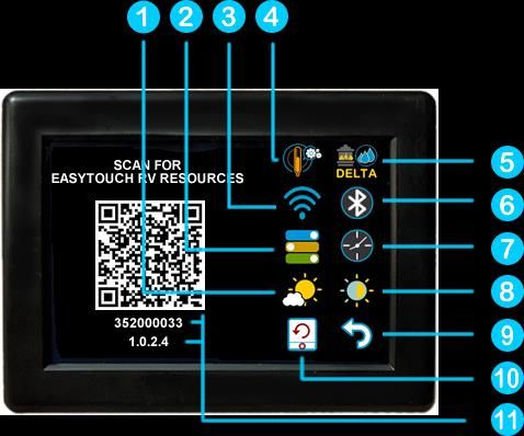
Contents
Installing the thermostat .............................................................................................................................. 3
   Removing the old thermostat ................................................................................................................... 3
   Using the push button terminals .............................................................................................................. 3
   Wiring the thermostat .............................................................................................................................. 4
   Mounting the thermostat ......................................................................................................................... 5
Initial setup instructions ............................................................................................................................... 6
   Available modes ........................................................................................................................................ 6
   Connecting remotely................................................................................................................................. 6
Operating the thermostat ............................................................................................................................. 7
   Main screen............................................................................................................................................... 7
   Away screen (Heat and cool set points) ................................................................................................... 9
   Schedule screen ...................................................................................................................................... 10
       Setting a change event........................................................................................................................ 10
       12- or 24-hour format ......................................................................................................................... 10
       Setting the time .................................................................................................................................. 10
       Enabling the schedule ......................................................................................................................... 10
Settings Screen............................................................................................................................................ 11
   Gas Heat Override ................................................................................................................................... 12
Smart device application only features ...................................................................................................... 12
   Reset device ............................................................................................................................................ 12
   Calibrate Touchscreen ............................................................................................................................ 12
   Check for updates ................................................................................................................................... 12
   Notifications ............................................................................................................................................ 12
Installation Troubleshooting ....................................................................................................................... 13
WIFI Troubleshooting.................................................................................................................................. 13
   No WIFI Icon ............................................................................................................................................ 13
   Red WIFI Icon .......................................................................................................................................... 13
Appendix A: Connecting remotely .............................................................................................................. 14
   First connection steps ............................................................................................................................. 14
   Adding a control ...................................................................................................................................... 14
   Connecting to a new WIFI network ........................................................................................................ 14
   Updating the thermostat ........................................................................................................................ 14

                                                                              2
©2021 Micro-Air Corp                                                                                                 August 2, 2021, revision 1.4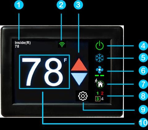
The EasyTouch 351 model thermostat was designed to replace certain
Dometic™ single-zone thermostats. Original thermostats replaced by this model are a
square design with a center LCD display and three buttons. If your thermostat is not
of this style, please contact Micro-Air https://www.micro-air.com/SupportRequest
to verify the thermostat you received is correct for your application.
Installing the thermostat
There are three steps to installing the thermostat. First remove your old
thermostat. Next disconnect and reconnect the wiring. Finally install the mounting pins to the wall and
mount your new thermostat.
Removing the old thermostat
We recommend you disconnect the DC power from the thermostat circuit in your RV. The power
wires are live and shorting them together could blow a fuse somewhere in the RV. Since these locations
are not well documented, removing power prevents having to find them.
There are two basic styles of three button thermostat. The first has a + and – button to change
temperature and on/off/mode button on the bottom with a small square display in the center. To
remove this style, depress the rectangular locking tab on the bottom of the thermostat with a small
screw driver. Pull the thermostat away from the wall from the bottom.
The second style has up and down arrows to change temperature, a rectangular LCD display and
a power/mode button. Carefully hold the base of the thermostat at the bottom while pulling the cover
plate away from the wall. It is easiest to pull at one of the corners to get the plastic to pop off.
Before removing the wiring, write down the color of the wire and the terminal each wire goes
to. Wires will be labeled +12V, COM or COMMS, and -12V or GND. disconnect the wiring and remove
any wall attachment screws. Remove the back plate from the wall.
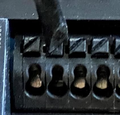
Using the push button terminals
Figure 1 shows a screwdriver depressing the push button
connector. The silver gate is opened for the wire to be inserted.
Releasing the button traps the wire and makes the connection.
Remove approximately 3/8 inch (1cm) of insulation from
the wire to be inserted. Use a small screw driver (not provided) or
similar tool to push down on the square push button. Insert the
wire in the insertion space and release the push button. Verify the
connection by gently pulling on the wire. Do not force excessive
wire down into the connector. If the stripped wire end is longer
than 3/8 inch, cut the end so there is no bare wire sticking out when Figure 12
properly inserted.
3
©2021 Micro-Air Corp August 2, 2021, revision 1.4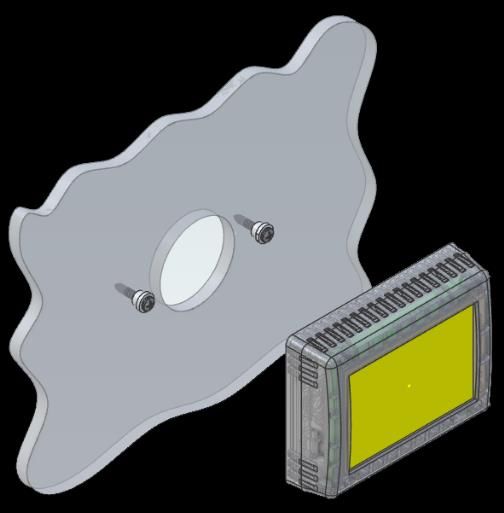
Wiring the thermostat
        There are three terminals on the back of EasyTouch labeled SIG, GND, and 12V. They will be
connected to the push terminals on the back of the EasyTouch thermostat. Use the information in Table
1 to determine the connections.

Table 1

            Terminal Labels
  Style 1      Style 2   EasyTouch
   GND          -12V        GND
   COM        COMMS         SIG
   +12V         12V+        12V

                                                  4
©2021 Micro-Air Corp                                                      August 2, 2021, revision 1.4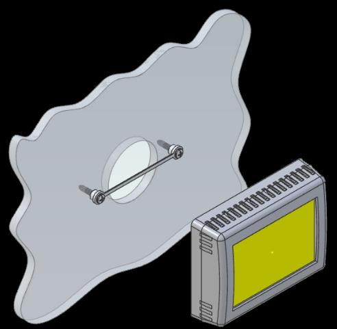
Mounting the thermostat

Step 1: Locate the mounting buttons
horizontally across the hole with the smaller
diameter against the wall.                          Step 4: Remove mounting tab before mounting
                                                    on the wall.

Step 2: Screw in one screw and level the
buttons so the display will be straight when
installed.

                                                    Step 5: Aligning the buttons with the holes in
                                                    the back of the display. Press the display against
                                                    the wall and gently slide the display down to
                                                    lock it in place.

Step 3: Screw in second screw making sure the
two buttons remain level.

                                                5
©2021 Micro-Air Corp                                                     August 2, 2021, revision 1.4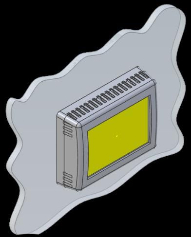
Initial setup instructions
Available modes
        Control boards in this system send data to the display that determines the available modes. No
configuration is necessary.

Connecting remotely
        This thermostat may be operated remotely using either Bluetooth or WIFI. Apps may be loaded
from the Google Play store or Apple App store. The first time the app is opened, it will ask to create an
account. A WIFI connection on your smart device is necessary for this step. Create your account and
follow the prompts to connect your thermostat.

       If a second user is going to use the thermostat remotely, they can use the same account and
password as the first user. Each thermostat can only be assigned to a single account.

                                                    6
©2021 Micro-Air Corp                                                          August 2, 2021, revision 1.4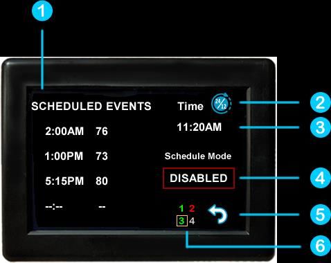
Operating the thermostat
    Main screen

    1. Inside temperature shows the ambient temperature of
       the room.
    2. WIFI indicator shows the state of the WIFI connection.
       Green indicates WIFI is connected properly, Red
       indicates connection to router only, bars indicate signal
       strength, and no symbol indicates no connection.
    3. Raise and lower the temperature set point using the
       red and blue arrows.
    4. Use the power button to turn the system on or off.
       Button is red for off and green for on.
    5. Pressing the mode icon changes from cooling or
       heating modes depending on what is available in your system. See table 2 for a list of all possible
       modes.

Table 2
                  Icon         Action             Icon                Action
                          Fan only                        Automatic cool/heat strip

                          Cool Only                       Automatic cool/furnace

                          Furnace                         Automatic cool/heat pump

                          Heat strip

                          Heat pump                       Zone off

                           Aqua Heat                        Zone on
                           mode (future
                           option)
    6.    Pressing the fan icon selects between manual (always on) fan speeds and automatic fan speeds.
          Automatic will turn the fan off after the heating or cooling cycle is completed. See table 3 for
          available fan speeds.

                                                     7
©2021 Micro-Air Corp                                                           August 2, 2021, revision 1.4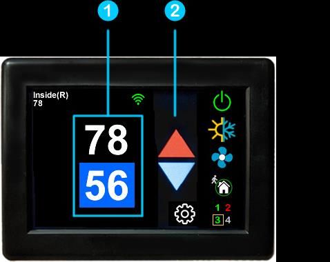
Table 3

           Icon          Indication                Action
                          Fan low                 Fan runs
                                             continually on low
                          Fan high               Fan runs
                                            continually on high

                          Auto fan            Fan cycles with
                                               compressor or
                                              electric element
                           Fan off                 No Fan

    7. Home-away-schedule icon. Pressing this button selects between these modes. Home mode is
       the normal operating mode using a single setpoint for temperature control. Schedule mode
       allows changing set points throughout the day programmatically. Away mode allows setting a
       heating and a cooling set point and automatically changing from heating to cooling.
    8. The zone selection button will show a zone in green when it is turned on. The zone number will
       show in gray if the zone is not available and in red if there is a fault with the zone.
    9. Pressing the gear will change the settings screen to allow additional setup functions.

    10. Pressing the set point will change the system units from °F to °C and back. The setpoint is also
        used as an indicator of system operation. A red set point indicates a heating cycle is in process.
        A blue set point indicates a cooling cycle is in process. A white icon indicates no cycle is in
        process.

                                                     8
©2021 Micro-Air Corp                                                           August 2, 2021, revision 1.4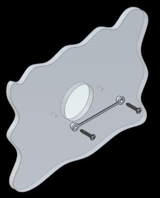
Away screen (Heat and cool set points)

        Away operation allows setting upper and lower limits for temperature with a non-operating
area or “dead band” in the middle. This can be useful when setting a higher daytime cooling
temperature and lower night time heating temperature. It can also be used to control the temperature
extremes when you are away from the RV. The mode selected must be an automatic mode to allow
both heating and cooling operation.

       1. Press the setpoints area to toggle between the selected value. A blue square will show
around the value you are changing. The upper value changes the cooling set point and the lower value
changes the heating set point.

       2. Use the up and down arrows to change the selected temperature value.

                                                  9
©2021 Micro-Air Corp                                                       August 2, 2021, revision 1.4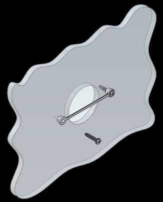
Schedule screen

        Set points may be changed on a time-based schedule. The mode used will be the heating or
        cooling mode set on the main screen.

Setting a change event
         1. Events will show --:-- when the event is disabled. Press the hours position to set the hours. A
flashing bar will appear under the hours along with up and down adjustment selectors. Use the
adjustment selectors to change the hours.

        Press the minutes to move the flashing bar under the minutes and allow ¼ hour adjustments.
Use the up and down adjustment selectors to make changes.

       Press the temperature to change the desired temperature set point. This is the temperature the
system will try to achieve after the time that was set.

12- or 24-hour format
        2. Press the time in the upper right to change 12 and 24-hour time formats.

Setting the time
       3. Time zone is set and saved whenever the thermostat connects using Bluetooth. Time is set on
power up through the internet connection, or whenever a connection is made on either Bluetooth or
WIFI.

Enabling the schedule
        4. Press the enabled/disabled button to enable the schedule. The schedule will be active and
make set point changes anytime the schedule is selected on the main screen. The Home/Schedule/Away
button will only toggle between schedule and away when the schedule is enabled. The button will only
select between home and away if the schedule is disabled. Away mode is not configurable on a
schedule.

        5. Press the round arrow icon to return to the regular settings screen.

                                                     10
©2021 Micro-Air Corp                                                            August 2, 2021, revision 1.4
Settings Screen
1. Day/Night mode. Day mode (shown above) will dim the display down to the screen saver set
point after 30 seconds. Night mode (moon icon) will turn off the back light after 30 seconds. The
display will brighten again once the touch screen is pressed. See (7) to set brightness.
2. The DIP switches icon is used to view the modes set on the control board dip switches.
3. WIFI is used to view your WIFI settings and MAC address. Changes to the WIFI connection must
be made using the smart device application.
4. Temperature adjustment is used to adjust the inside temperature with an offset. This will only
apply to zone 1.
5. The temperature delta icon allows adjustment for one- or two-degree temperature changes
before a cycle begins in furnace or aqua mode.
6. Bluetooth is used to reset the Bluetooth password. This password is saved from your account
password. Only one account at a time may access the thermostat. Reset the password whenever
you change your account password.
7. Schedule is used to change the set point automatically at a pre-determined time. See Schedule
operation for more details.
8. Brightness settings allow dimming the normal brightness and setting the screen saver
brightness.
9. The back icon will return the display to the operating screen.
10. Reset all will reset the thermostat to factory settings including all set points, schedule events,
and other settings.
11. The QR code will bring you to the Micro-Air EasyTouch page when selected using a QR
compatible phone app. Below the QR code is the serial number for the thermostat and the
firmware revision for the thermostat. Firmware updates can be checked for in the smart device
application.
11
©2021 Micro-Air Corp August 2, 2021, revision 1.4Gas Heat Override
This function is handled by the control board and not the thermostat. It will activate when the
outside temperature falls below the minimum heat pump operating temperature if available on the
system.
Smart device application only features
Reset device
This Bluetooth only feature allows resetting the display just as if you removed and restored
power.
Calibrate Touchscreen
It is normally not necessary to recalibrate the touchscreen. This selection prompts the user to
press the four corners of the display then test the calibration using three diagonal marks. This feature is
only available from Bluetooth since being at the thermostat is required.
Check for updates
Checks to see if any updates are available for the thermostat. The smart device application must
have internet and the thermostat must be connected to WIFI with a green WIFI symbol. Tap Check for
Updates and follow the prompts.
Notifications
Notifications provide a way for the thermostat to communicate back to a smart device like a
tablet or phone. These notifications are indications of the temperature exceeding a set limit. Limits are
set by connecting to the thermostat in the app, selecting the settings gear, and then selecting
notifications. A minimum and maximum allowed temperature can be set. Table 4 shows an example of
operation with an 80°F maximum temperature set. Notification will be sent for each degree it rises
above the maximum temperature. If temperature drops, no notification will be sent unless the
temperature exceeds the last maximum temperature again (82 in the example). If the temperature
drops two degrees below the set maximum, (78 in the example) it will again alert for each degree above
the set maximum. This behavior helps avoid nuisance notifications to your smart device.
Table 4
Temperature °F Action
80 Send first notification
81 Send another notification
82 Send another notification
81…79 Temperature drops, no
notification
78 Max temp resets
12
©2021 Micro-Air Corp August 2, 2021, revision 1.4Installation Troubleshooting
The most common problem is not knowing the thermostat operation. If the system is running a
heating or cooling cycle, the set point will turn red for heating and blue for cooling. When the
thermostat turns white, the heat pump, heat strip and furnace should all be off. The fan may continue to
run for a while after the cycle completes. If a fan is left in a manual mode, it will not shut off.
WIFI Troubleshooting
No WIFI Icon
• SSID (Network name) and password are both case sensitive.
• Be sure you are connecting to a 2.4 GHz network and not a 5GHz or 6GHz network.
• Set the security to WPA2 and TKIP+AES if you are having trouble.
• The thermostat has a limit of 31 characters for the SSID and 50 for the password.
• The number of devices limit for the network is not full.
• The WIFI source is not out of range or metal partitions blocking the signal
• Reset the router to renew the DHCP lease.
• If you are in a metal enclosure, try moving the router or thermostat a few inches (even if
temporary) and trying again.
• If using MAC filtering, add the thermostat to the allowed devices list.
• Be sure the router SSID is not set for “Hidden”.
Red WIFI Icon
• The router must have an internet connection
• Server may be down, check back at a later time
• Be sure there is no firewall in the router blocking the incoming messages (port 443, HTTPS).
13
©2021 Micro-Air Corp August 2, 2021, revision 1.4Appendix A: Connecting remotely
First connection steps
1. This thermostat uses BLE which is a special implementation of Bluetooth. It is not necessary to
“Pair” the thermostat with the phone but an account must be created for operation.
2. Start the app on your smart device. The app will open and if you have not entered your account
information, it will ask you to create an account. Enter your name, email and a password at the
prompts. The system will send a confirmation email to your inbox. Enter the number in the
confirmation email when asked.
3. Once the account is created, the application may ask to add a device. If your device is powered
it will show in the list to be added to your account. Select the control and enter a name or
location for the control.
4. If you added a control, the app will ask if you want to connect to WIFI now. Enter your SSID
(network name) and password in the boxes.
Adding a control
Follow the next steps if the account process does not add a control or a second thermostat is to
be added.
1. Press “Add” on the top of the selection screen (Apple) or press the settings gear and “Add
Device” (Android).
2. The second thermostat should be listed in the new selection window. Select the device and
enter a name for the device.
3. Press OK and the screen will return to the settings menu (Android) or the selection screen
(Apple). Android users should press the back button to get to the selection screen.
4. Select the device name to open the thermostat screen.
Connecting to a new WIFI network
1. Connect to the thermostat in Bluetooth (Apple) and press the settings gear.
2. Select WIFI Setup from the settings window.
3. Enter the SSID (network name) and password (Both case sensitive).
4. Press OK and the screen will return to the selection screen. The thermostat will reset and a
green WIFI symbol will appear on the thermostat screen if the connection was successful.
Updating the thermostat
Ensuring you have the latest thermostat software is key to having all the latest features.
1. Ensure the thermostat is connected to WIFI with a green WIFI symbol.
2. Connect to the thermostat and press the settings gear, then tap Check for Updates.
3. Follow the prompts to update the thermostat or ensure that you already have the latest
software.
14
©2021 Micro-Air Corp August 2, 2021, revision 1.4You can also read