Determination of Coal Cutting Forces Using the Cutting Head of POU-BW/01-WAP Device
←
→
Page content transcription
If your browser does not render page correctly, please read the page content below
Determination of Coal Cutting Forces Using
                                 the Cutting Head of POU-BW/01-WAP Device
doi:10.2478/mape-2021-0025
Date of submission to the Editor: 05/2021             MAPE 2021, volume 4, issue 1, pp. 281-289
Date of acceptance by the Editor: 07/2021

Witold Biały
ORCID ID: 0000-0003-2313-0230
Silesian University of Technology, Poland

Jiri Fries
ORCID ID: 0000-0001-9776-6878
VSB-Technical University of Ostrava, Czech Republic

Greg Galecki
Missouri University of Science and Technology, USA

INTRODUCTION
The POU-BW/01-WAP device offers a possibility to measure the cutting forces
applied to knives during the mining process. The resistance extensometry
method ensures that the cutting forces can be measured with sufficient accuracy
as it enables accurate strain measurement. In practice it consists of measuring
elongations on the body surface under the influence of known external forces.
The measurement principle consists of determining a measuring segment of
original length L, called the measuring base, measured in the desired direction,
                                                λ
and then measuring the increase in its length L under the influence of external
forces. For a uniform deformation state, the quotient determines the specific
elongation
                     λ
                 ε= L                                                           (1)
Knowing the elastic constant of material under test and the result of
measurement of specific elongation, it is possible, using Hooke’s law, to
calculate the values of stress occurring in the material, and through it other
mechanical quantities, such as force, bending moment, pressure, etc.
If the tests are to be carried out under normal operating conditions, it is best to
use the resistance strain method, which uses strain gauges classified as
electrical strain gauges. This method provides the possibility of making multi-
point measurements with remote recording of results, or with their direct transfer
to a recording device (memory, computer). Such a measuring system has a very
low inertia, which allows measurements of quickly changing quantities.
The electrical strain gauge method is based on the property of a metal wire to
change its electrical resistance due to changes in its cross-section and length,
induced by deformation, as a result of external force.

  Contact address: witold.bialy@polsl.pl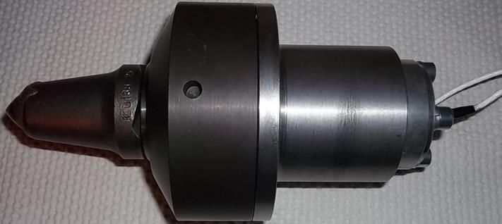
282        Multidisciplinary Aspects of Production Engineering – MAPE vol. 4, issue 1, 2021

Resistance strain gauges take the form of a series of wires properly adhered to
a substrate and attached to the test surface with a special adhesive. Currently,
foil resistance strain gauges are commonly used, where the resistance grid is
made of thin metal foil between two layers of plastic foil. Electrical wires are
connected to the ends of strain gauge leads, connecting the strain gauge to the
measuring system. The measuring system consists of a power source, a strain
gauge bridge with measuring and compensation strain gauge (its task is to
compensate the influence of side factors, mainly temperature), measuring
amplifier, increasing the signal to a value suitable for the recording device. The
measuring strain gauge is one of the branches of the bridge, in the other
branches of which there are reference elements (resistances). The state when
no current flows in the diagonal branch of the bridge is called the equilibrium
state, and the relationships between the parameters of individual branches in
equilibrium are called the equilibrium conditions.
Measurement bridges are divided into balanced and unbalanced. In the case of
a balanced bridge, the measurement consists in bringing the bridge to
equilibrium state by changing the values of reference elements and calculating
– from the equilibrium conditions – the parameters of tested element. For an
unbalanced bridge being previously in equilibrium, the voltage (in the diagonal
branch of the bridge) is measured, which arises as a result of changes in
resistance of strain gauge attached to the tested element, which is also one of
the branches of that bridge.
The main problem in conducting measurements using the resistance
extensometry method is to find a place for attaching strain gauges on the tested
element in such a way that the interpretation of obtained measurement results
is easy and unambiguous.

FORCES IN THE CUTTING PROCESS
The mining process that takes place under natural conditions using a specific
technology is a complex process (Biały 2002, 2011, 2013, 1013a, 2014, 2015,
Krauze & Kotwica, 2007, Myszkowski & Paschedag, 2008, Krauze et al. 2015,
Bołoz 2018). Most often this process differs significantly from the adopted
model. Due to the fact that tangential-rotary knives are most commonly used in
modern longwall drum shearers (Fig. 1), the most serious problem was to design
the measuring element of the device in such a way that the measurement is
possible at all (Biały 2013b, 2014a). Strain gauges should be arranged to allow
direct measurement of these forces.

      Fig. 1 Tangential-rotary knife used in the head of POU-BW/01-WAP device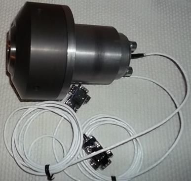
Engineering and Technology                                                    283

In fact, the tangential-rotary knives have the ability to rotate in their holders,
which makes it impossible to attach strain gauges directly to them in such a way
as to receive a signal. A solution has been proposed that enables the forces to
be measured in a simple way and then, thanks to the known geometrical
parameters of the device, allows the load parameters, e.g. in a form of forces
(force moments), to be calculated using elementary equations. It is also
important to be able to statistically process the results of any number of
measurements, each of which is a record of the load course of a given cutter in
real time.
During mining, a force acts on the shearer’s knife (Fig. 1), which is divided into
the following components (Fig. 2) (Biały 2005, 2009):
Fs – cutting force,
Fd – pressure force applied to the mining a body of coal,
Fb – lateral force (thrust).

                   Fig. 2 Force components in the mining process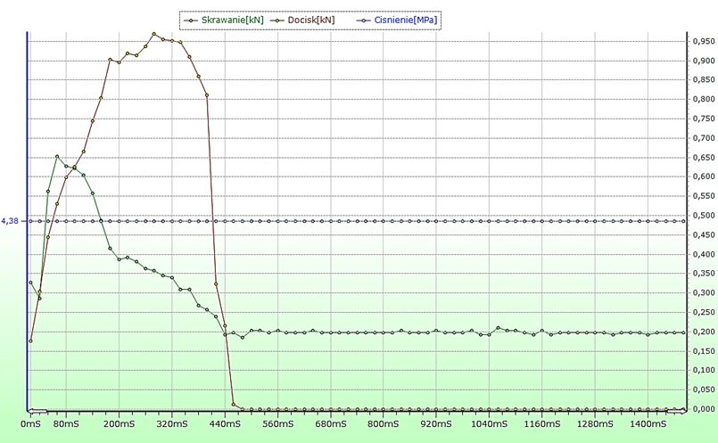
284 Multidisciplinary Aspects of Production Engineering – MAPE vol. 4, issue 1, 2021
In the POU-BW/01-WAP device, the measuring head (Fig. 3), has been
constructed in such a way that it allows to measure simultaneously two of three
forces occurring during the cutting process: cutting force Fs (Fig. 4) and pressure
force applied to the mining a body of coal Fd (Fig. 5).
The value of cutting force Fs is measured from the force moment that bends the
holder in which the knife is fixed. While the knife pressure force Fd, is measured
by the knife pressure on the body base, also by means of strain gauges.
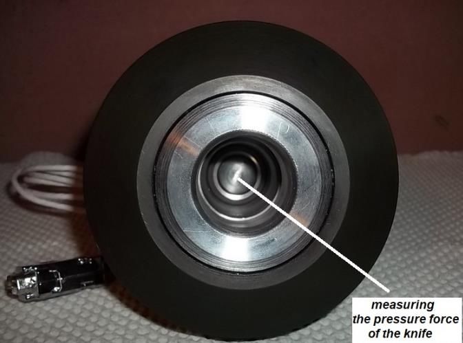
Fig. 3 Measuring head body with measuring blade
Fig. 4 Sensor for measuring the cutting force Fs
Fig. 5 Knife force sensor applied to the unmined coal Fd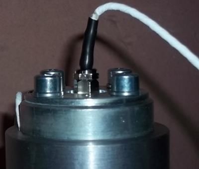
Engineering and Technology                                                           285

The strain gauges were adhered in such a way that their base was in
accordance with the direction of the greatest stresses (Fig. 6, 7), at the same
time as the greatest change in the length of measurement element (bending).

    Fig. 6 Place of strain gauges adhesion for measurement of the cutting force Fs

   Fig. 7 Place of strain gauges adhesion for measurement of the pressure force Fd

Compensating strain gauges are adhered across from the active ones, i.e. in
the direction of minimum stress. This configuration provides the greatest bridge
deviation from equilibrium as the stress changes in a measuring element. On
the other hand, attaching the compensating strain gauge in the same place as
the active one causes that they are at the same temperature and the
286 Multidisciplinary Aspects of Production Engineering – MAPE vol. 4, issue 1, 2021
temperature-induced changes in their resistance are the same. Whereas in a
bridge they interact in the opposite way, i.e. they compensate each other.
Separation of the cutting force component Fs is obtained using the
compensation method, by adding and subtracting the results (in each case) from
the bridge located on the bended side (Fig. 6). The knife pressure force Fd is
obtained from the strain gauge bridge located in the lower part of cutting head,
where compression occurs (Fig. 7).
The cutting head of POU-BW-01-WAP device was calibrated for known loads
on the test stand. Therefore, it is assured that the results obtained are reliable.
Moreover, since the device is equipped with force and pressure sensors, it is
possible to determine the cutting forces from two independent measurement
sources, and thus verify the obtained measurement results – cutting force (Fs)
and knife pressure force (Fd).
The cutting head with strain gauge bridges for measurement and recording of
two forces involved in the coal cutting process is shown in Figure 8.
Fig. 8 POU-BW/01-WAP cutting head with strain gauge bridges
The blade used in the cutting head is a tangential-rotary knife. This knife has the
ability to rotate freely during the cutting tests.
ANALYSIS OF AW-PSSW COAL CUTTING FORCE MEASUREMENT
RESULTS
The AW-PSSW program (Fig. 9) allows visualization and analysis of collected
information from the Coal Cutting Force Measurement system (Documentation,Engineering and Technology 287
2012, 2012a). On the monitor screen, there are three values that can be read
directly: cutting force Fs, pressure force Fd and pressure value.
Fig. 9 Graphical layout of the AW-PSSW program
The main program options include:
• browsing of collected files in the form of entries arranged in a table,
• conversion of DAT files to a spreadsheet,
• data visualization in the form of graphs,
• data analysis using histogram and outcome statistics,
• measurement printout,
• measurement export to a text file.
The program requires a PC with Windows XP and Micrsotf.NET Framework 3.5
installed for proper operation.
CONCLUSION
In order to correctly select or predict the shearer loader power in real geological-
mining conditions, it is necessary to know the force components involved in this
process. For this purpose, the POU-BW/01-WAP device is used, which allows
the measurement and recording of two force components involved in this
process (Fs and Fd).
It is the only device in the world with which it is possible to determine the two
force components involved in the machining process. Determination of force
components involved in the cutting process, is possible by using two
independent measuring blocks, which is a strain gauge force sensors: cutting
(Fs) and knife pressure (Fd). In order to register these forces, a real mining knife
used in longwall shearer drums was applied – i.e. tangential-rotary.
Knowing the force value required for the cutting operation, it is possible to
determine two parameters: workability index A, or energy workability index AE.288 Multidisciplinary Aspects of Production Engineering – MAPE vol. 4, issue 1, 2021
The workability index A is defined as the ratio of average force (Fśr) to depth of
cut (g):
Fsr kN
g m
A= (2)
While the energy workability index AE is defined as follows:
Fsr l MJ
Q m 3
AE = (3)
where:
Fśr – average cutting force per cutting length,
l – length of the cutting groove,
Q – volume of mined coal (rock).
This device uses the most modern solutions in terms of construction as well as
measurement and recording of measured values. The POU-BW/01-WAP device
can be used in real conditions (mining plants) as it has ATEX certificate that
allows operation in potentially explosive atmospheres – according to the
94/9/EC directive.
ACKNOWLEDGMENTS
The article was written in support of BK-273/ROZ3/2021 (13/030/BK_21/0065)
research under the title "Department of Production Engineering’ resources
development for carrying out activities in the areas related to the Silesian
University of Technology Priority Research Areas”.
REFERENCES
Biały W. (2002). The side-crumble angle ψ of coal and the energy consumption of the
mining process as a function of the vertical component σz of exploitation pressure.
Polska Akademia Nauk, Archiwum Górnictwa tom 47 nr 3. pp. 361-384.
Biały W. (2005) Empiryczne prognozowanie mocy ścianowych kombajnów bębnowych.
Wydawnictwo Politechniki Śląskiej. Seria: Górnictwo z. 262 Gliwice.
Biały W. (2009) Volba dobývacích kombajnů na základě výzkumů rozpojitelnosti uhlí.
VŠB-Technická univerzita Ostrava, Fakulta strojní, Ostrava 2009.
Biały W. (2011). The selection of optimal method determining mechanical properties of
coal layers. Management Systems in Production Engineering no. 2 ISSN 2299‐
0461. pp. 26-30.
Biały W. (2013). Innowacyjne narzędzia do wyznaczania właściwości mechanicznych
węgla. Przegląd Górniczy nr 6. Katowice. ISSN 0033-26X. pp. 17-26.
Biały W. (2013a). New devices used in determining and assessing mechanical
characteristics of coal. 13th SGEM GeoConference on Science and Technologies
In Geology, Exploration and Mining, SGEM2013 Conference Proceedings, ISBN
978-954-91818-7-6/ISSN 1314-2704 June 16-22.2013. Vol. 1. pp. 547-554.
Biały W. (2013b) Sposób pomiaru sił na głowicy urabiającej przyrządu POU-BW/01-
WAP. Rozdział 8. Problemy bezpieczeństwa w budowie i eksploatacji maszyn i
urządzeń górnictwa podziemnego. Monografia red. Krauze K. Centrum Badań i
Dozoru Górnictwa Podziemnego Sp. z o.o. Lędziny 2013.
Biały W. (2014). Coal cutting force measurment systems – (CCFM). 14th SGEM
GeoConference on Science and Technologies In Geology, Exploration and
Mining, SGEM2014 Conference Proceedings, June 17-26, 2014, Vol. III,
BUŁGARIA ISBN 978-619-7105-09-4/ISSN 1314-2704. pp. 91-98.Engineering and Technology 289
Biały W. (2014a) Zasoby węgla kamiennego. Urabialność pokładów węglowych.
Wydawnictwo PA NOVA SA. Gliwice 2014.
Biały W. (2015). „Innovative solutions applied in tools for determining coal mechanical
proprerties” Management Systems in Production Engineering vol. 4(20). Gliwice.
ISSN 2299-0461. pp. 202-209. DOI: 10.12914/MSPE-02-04-2015
Bołoz Ł. (2018). Model tests of longwall shearer with string feed system, Archives of
Mining Sciences, vol. 63 no. 1, pp. 61-74, DOI 10.24425/118885.
Krauze K., Kotwica K. (2007). Selection and Underground Tests of the Rotary
Tangential Cutting Picks used in Cutting Heads of the Longwall and Roadway
Miners. Polska Akademia Nauk, Archiwum Górnictwa tom 52 nr 2. pp. 195-217.
Krauze K., Bołoz Ł., Wydro T. (2015). Parametric factors for the tangential-rotary picks
quality assessment, Archives of Mining Sciences, vol. 60, no. 1, DOI:
10.1515/amsc-2015-0018,
Myszkowski M., Paschedag U. (2008). Longwall mining In seams of medium thickness
– comparison between shearer and plow. 21st. Word Mining Congress. Kraków.
Dokumentacja Techniczno-Ruchowa POU-BW/01-WAP, (2012). Welding Alloys
Polska sp. z o.o. Gliwice.
Dokumentacja Techniczno-Ruchowa (2012a). Urządzenie do Pomiaru Siły Skrawania
Węgla. ITI EMAG. Katowice.
Abstract: The paper presents a method for measuring and recording the forces
involved in the coal cutting process. Moreover, a method for visualization of all forces
involved in the cutting process was described. In the following part, the construction
and principle of operation of a device for determination of forces involved in the
cutting process (coal mining), referred to by the author as POU-BW/01-WAP, are
presented. Resistance extensometry was used to measure the forces. This is the
only device in the world that determines two of three force components that take part
in the cutting process. For this purpose, two independent measuring blocks were
used, which are strain gauges of force: cutting (Fs) and knife pressure (Fd). In order
to register these forces, a real mining knife used in longwall shearer drums was
applied – i.e. tangential-rotary. The equipment has the ATEX certificate allowing for
operation in real conditions as a device intended for use in potentially explosive
atmospheres – in accordance with the directive 94/9/EC. It has received many
awards at world fairs for inventions and innovative solutions.
Keywords: workability, cutting forces, measurement, recording, strain gaugesYou can also read