Hydraulic Analysis Of Ski Jump As An Energy Dissipator - sersc
←
→
Page content transcription
If your browser does not render page correctly, please read the page content below
International Journal of Future Generation Communication and Networking
 Vol. 13, No. 3s, (2020), pp. 415–420

 Hydraulic Analysis Of Ski Jump As An Energy Dissipator
Sayali Ashok Thorat#1, Aishwarya Vinayak Nale#2 Yuvraj Arjun Vyavahare#3 Shahrukh Salim
 Shaikh#4
 #1-3
 UG Students, Civil Engineering Department, Savitribai Phule Pune University, Pune
 #4
 Assistant Professor, Civil Engineering Department, Savitribai Phule Pune University, Pune
 1
 sayaleethorat123@gmail.com
 2
 ash5nov@gmail.com
 3
 yuvrajvyavahare444@gmail.com
 4
 shahrukh.shaikh.sits@sinhgad,edu

 Abstract
One of the most effective and economical methods for the dissipation of hydraulic energy from flood
waters is to project the flows into a free trajectory jet form to a location where the impact creates a
plunge pool in the downstream river bed. This type of energy dissipation can be created by a ski-
jump energy dissipator which has become an increasingly popular form of hydraulic energy
dissipation for large dams in recent years due to its ability to safely convey high velocity flow in
excess of 30m/s to the downstream river, however very limited definitive and comprehensive
guidelines have been created. There is not only insufficient documentation for the conceptual and
detailed design of ski-jump energy dissipators, there is also insufficient documentation for the
dimensioning of the downstream plunge pools. Both are necessary to guarantee that the passage of
major floods do not threaten the structural integrity of the permanent works.

Keyword: hydraulic energy, dissipation, ski-jump, trajectory.

 I. INTRODUCTION
Hydraulic structures may be defined as a structure which allows the improvement and/or modification
of flow features in water. The hydraulic assessment of such structure is necessary because such
structure requires high strength since it is subjected by high velocities, large discharges as well as
large hydrostatic pressures.

 FIG.1. HYDRAULIC STRUCTURE (UKAI DAM)

 The most essential civil engineering activity throughout all history is said to be dam engineering.
Dams in their early existence were constructed with the primary function of a storage reservoir so that
 415
ISSN: 2233-7857 IJFGCN
Copyright ⓒ2020 SERSC
International Journal of Future Generation Communication and Networking
 Vol. 13, No. 3s, (2020), pp. 415–420

access to water was possible throughout the year including the dry season. Dams were envisioned to
fulfill the arising need for irrigation at the time of organized agricultural development. There was a
realization in the nineteenth century that the storage of water in dams and reservoirs played an
essential role in society in relation to topics such as water supply, flood protection as well as energy
generation.

 Dams were built taller and wider with the advancement of dam engineering technologies and
construction technique, and therefore discharges became larger and flow velocities became
increasingly higher. Succeeding the Second World War the global development of large dams in
excess of 100m in height is remarkably illustrated by the dramatic increase in the total number of
dams from 30 in 1945 to 500 by 1990 (Hager & Boes, 2014).
 Along with the advancements in dam engineering technology new problems such as energy
dissipation and scour arose. One of the most effective and economical methods for the dissipation of
hydraulic energy from taller dam is Ski-jump bucket energy dissipator. This research includes
hydraulic testing of Ski-jump bucket energy dissipator with and without deflector. Ski-jump bucket
energy dissipator become popular for large dams in recent years due to its ability to safely convey
high velocity flow in excess of 20m/s to the downstream plunge pool.

CLASSIFICATION OF DAM:
The three main categories of dam classification are:
I. Classification according to function

II. Classification according to hydraulic design and

III. Classification according to construction materials.

I. Classification according to function:
The relevant examples of dam which classified under this category are a Storage dam, Diversion dam
and Detention dam.

II. Classification by hydraulic design:
In terms of hydraulic design dams may be classified as either overflow or non-overflow dams.
Overflow dams are designed to convey flow over the crest and non-overflow dams are those designed
so that overtopping does not exist.

III. Classification by materials:
The most common types of dam classified by materials are Earth fill dams, Rock fill dams and
Concrete gravity dams.

ENERGY DISSIPATING STRUCTURE:
The water flowing over the spillway acquires a lot of kinetic energy by the time it reaches near the
foot of the spillway. The arrangement made to dissipate this huge kinetic energy of water is known as
energy dissipater. Energy dissipater is the structure constructed not only to protect the riverbed and
banks from erosion, but also to ensure that the dam itself and adjoining structures are not undermined.
The energy dissipators for spillways can be grouped under the following three categories i.e.:
I. Hydraulic jump stilling basins energy dissipator

 416
ISSN: 2233-7857 IJFGCN
Copyright ⓒ2020 SERSC
International Journal of Future Generation Communication and Networking
 Vol. 13, No. 3s, (2020), pp. 415–420

II. Impact type energy dissipator

III. Buckets types of energy dissipator

DEFLECTOR:
The deflector always started at the beginning of the Ski-jump bucket and ended at its downstream
crest. Deflectors are the element provided at the outlet to deflect the trajectory into an area of plunge
pool where sound rock is present so that erosion will be less. Deflectors are also used:
 1. To enhance jet dispersion,

 2. To spread and

 3. To elongate the jet trajectory.

Fig shows arrangement of deflector on ski-jump bucket used by Roman Juan in his study. Roman
Juan investigated the main features of flip buckets including scale effects in hydraulic
models, bucket pressure distribution, and nappe trajectories with and without the presence of
deflectors.

FIG.2. SKI-JUMP BUCKET WITH DEFLECTOR (SHOWN IN ROMAN JUON 2000)

 II. THE PRINCIPLE FEATURES OF HYDRAULIC DESIGN OF TRAJECTORY BUCKET

Trajectory bucket type energy dissipator is considered more suitable when:
a) Tailwater depth is much lower than the sequent depth of hydraulic jump, thus preventing formation
of the jump;
b) By locating at higher level, it may be used in case of higher tailwater depths also, if economy
permits; and
c) Bed of the river channel downstream is composed of sound rock.
Provision of conventional hydraulic jump type apron or a roller bucket involves considerable
excavation in hard strata which can be reduced appreciably. It is also necessary to have sufficient
 417
ISSN: 2233-7857 IJFGCN
Copyright ⓒ2020 SERSC
International Journal of Future Generation Communication and Networking
 Vol. 13, No. 3s, (2020), pp. 415–420

straight reach in the downstream of a ski-jump bucket. The flow coming down the spillway is thrown
away in air from the toe of the structure to a considerable distance as a free discharging upturned jet
which falls on the channel bed downstream. The hard bed can tolerate the spray from the jet and
erosion by the plunging jet would not pose any significant problem for the safety of the structure.
Thus, although there is very little energy dissipation within the bucket itself, possible channel bed
erosion close to the downstream toe of the dam is minimized. In the trajectory bucket, only part of the
energy is dissipated through interaction of the jet with the surrounding air. The remaining energy is
imparted to the channel bed below. The channel bed should consist of sound, hard strata and should
be free from laminations, joints and weak pockets to withstand the impact of jet. The design of the
trajectory bucket presupposes the formation of large craters or scour holes at the zone of impact of the
jet during the initial years of operation and, therefore, the design shall be restricted to sites where
generally sound rock is available in the river bed. Special care shall be taken to strengthen weak
pockets in the bed located in a length of about 15 m downstream of the bucket.

FIG.3. TRAJECTOTY BUCKET ENERGY DISSIPATOR

III. HYDRAULIC MODEL

 A HYDRAULIC MODEL OF OGEE SPILLWAY WITH A SKI-JUMP ENERGY DISSIPATER WAS DESIGNED
 AND FABRICATED. THE HYDRAULIC MODEL STUDY WAS CONDUCTED INSIDE THE FLUID
 MECHANICS LABORATORY DEPARTMENT OF CIVIL ENGINEERING, AISSMS COLLEGE OF
 ENGINEERING PUNE. THE HYDRAULIC MODEL WILL BE FIXED IN HYDRAULIC FLUME. THE
 LABORATORY CREATED A CONTROLLED ENVIRONMENT WHERE NO EXTERNAL FACTORS, SUCH AS
 WEATHER, COULD HAVE AN INFLUENCE ON THE SPECIFIC TESTS OR THE DATA ACQUIRED. WATER
 WAS PUMPED TO THE HYDRAULIC PUMP AT THE INLET OF THE HYDRAULIC FLUME WHERE
 CONSTANT LEVEL OF WATER BEHIND THE SPILLWAY MODEL WAS ABLE TO MAINTAIN AND WATER
 WOULD BE ALLOWED TO OVERFLOW ABOVE THE CREST CONTROLLED BY THE RADIAL GATE
 PROVIDED.

 418
ISSN: 2233-7857 IJFGCN
Copyright ⓒ2020 SERSC
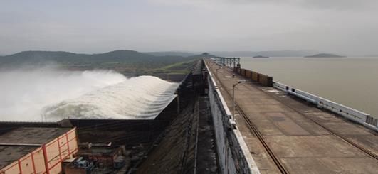
International Journal of Future Generation Communication and Networking Vol. 13, No. 3s, (2020), pp. 415–420 FIGURE 4. SCHTEMATIC DIAGRAM OF EXPERIMENTAL SETUP Figure 4 Shows a schematic diagram of the experimental setup with all relevant components. The main components associated are: Storage Tank Pump Inlet Pipe Valve Hydraulic Flume Ogee Spillway Radial Gate Deflector Bucket The storage tank for pumping the water and collecting the water back in the tank is used with size 1.5m x 0.8m x 1.2m. Centrifugal pump was used for pumping the water from the storage tank to the hydraulic flume through conduit pipe. A pump with 1.572 HP was used with speed of 2900 rpm and overall efficiency with 45% and maximum discharge of 10.5 lit/sec. A valve was provided before the water entering in hydraulic flume to control the flow of water or the discharge. Valve helps to regulate the flow of water. An ogee spillway was designed for maximum discharge condition. The arrangement of radial gate was provided on the fabricated flume for regulating the flow of water above the crest of the designed spillway. IV. HYDRAULIC MODEL DESIGN The ski-jump hydraulic model was designed with a scale of 1:100. This scale was chosen depending upon maximum discharge of hydraulic flume. The hydraulic model was designed to be geometrically similar to the prototype (Discharge 946.90 m3/s, width 30m and height 21.2m) for Bhama Askhed dam spillway and therefore the flows act in agreement with the Froude’s Law. Which is valid when the ratio of gravitational and inertial forces acting on a fluid particle are equal in the model and prototype therefore resulting in the following relationship between the prototype and model: = 419 ISSN: 2233-7857 IJFGCN Copyright ⓒ2020 SERSC
International Journal of Future Generation Communication and Networking Vol. 13, No. 3s, (2020), pp. 415–420 V. CONCLUSION In this project, 1:100 physical model of a ski-jump deflector bucket was hydraulically tested where two different ski-jump bucket designs with ten flow conditions were analysed to determine a design that maximizes energy dissipation and minimizes trajectory throw length and width of impact at tail water pool level. In order to quantify the energy dissipation of the different flip bucket designs, a combined analysis of the trajectory profiles, impact width, plunge pool depth, depth at lip of bucket were conducted. This experiment concludes that: The maximum height of the trajectory for deflector bucket was found to be always greater than the conventional ski-jump bucket for all flow conditions of discharge. The lower trajectory distance and middle trajectory distance were less for deflector bucket as compared to the conventional ski-jump bucket. The upper trajectory distance for deflector bucket was always greater than the conventional ski-jump for all flow conditions. REFERENCES [1] Shangtuo, Qian.,Jianhua, Wu., and Fei, Ma. (2016). “Hydraulic Performance of Ski-Jump-Step Energy Dissipater.” J. Hydraul. Eng., 05016004:1-7. [2] Jian-hua, WU.,Zhun XU., and Li, YAO. (2016). “Ski-jump trajectory based on take-off velocity.” J. Hydrodynamics., 28(1):166-169. [3] Pfister, M., Hager, W. H., and Boes, R. M. (2014). “Trajectories and air flow features of ski jump-generated jets.” J. Hydraul. Res., 52(3), 336–346. [4] Schmocker, L., Pfister, M., Hager, W. H., and Minor, H. E. (2008). “Aeration characteristics of ski jump jets.” J. Hydraul. Eng., 134(1): 90-97. [5] Steiner, R., Hager, W. H., and Minor, H. E. (2008). “Deflector ski jump hydraulics.” J. Hydraul. Eng., 134(5): 562-571. [6] Heller, V., Hager, W. H., and Minor, H.E. (2005). “Ski jump hydraulics.” J. Hydraul. Eng., 131(5): 347-355. [7] V. S. Ramarao., K. T. More., M. R. Bhajantri., and V. V. Bhosekar.(2016) “Assessment of Scour Downstream of Spillway with Submerged Ski Jump Buckets.”21st International Conference on Hydraulics, Water Resources and Coastal Engineering. [8] B .S. Sundarlal., Dr. M.R. Bhajantri., Dr.(Mrs.) V.V.Bhosekar., B.M.Simpiger., Amol. H. Gaikwad. (2016) “Review of critical issues in the design of spillway and energy dissipator, mangdechhu hydroelectric project, Bhutan.” 21st International Conference on Hydraulics, Water Resources and Coastal Engineering. [9] S. K. Mujumdar., P. L. Patel. (2001) “Model study of ski-jump type of energy dissipator.” International Conference on Hydraulics, Water Resources and Coastal Engineering. [10] Jill, Lucas., Willi, H. Hager., and Robert, M. Boes. (2013). “Deflector Effect on Chute Flow.”J. Hydraul. Eng., 139(4): 444-449. [11] Juon, R., and Hager, W. H. (2000). “Flip bucket without and with deflectors.” J. Hydraul. Eng., 126(11): 837-845. [12] Bureau of Indian standards. “Criteria for hydraulic design of bucket type of energy dissipators.” IS: 7365: 2010 (Second revision). 420 ISSN: 2233-7857 IJFGCN Copyright ⓒ2020 SERSC
You can also read