SITEAWARE VIEWER QUICK START GUIDE
←
→
Page content transcription
If your browser does not render page correctly, please read the page content below
SiteAware Viewer
   Quick Start Guide
Login Screen

1. Enter SiteAware provided username (an email address) and password

2. Click ‘Login’

3. Click ‘Forgot Password’ to request a password reset

4. ‘Sign Up’ option is for trial users
Main Menu

1. Scroll to required site
2. Alternatively, use Map View to select by site coordinates
3. Use ‘Sort By…’ button to sort by last scan date or name
4. Use Search function to search for exact matches of sites or locations within
User Menu

1. Reached by clicking user icon in top right corner
2. Displays current user logged in
3. Unit system toggle: Metric or Imperial
4. Click Help for technical support
5. Click Logout to end session and logout
Site Menu

1. Select required location by clicking on relevant dropped pin (Blue pin marks Site Map)
2. Rollover dropped pins to get their location name
3. Alternatively, use ‘Location…’ dropdown to select by name
4. Use datepicker to load an archived site view
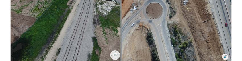
Location View

1. By default, shows 3D model of latest scan in point cloud format (in Single View mode)
2. Use Mouse to navigate model: (left click+drag) to rotate, (right click+drag) to pan, scroll
   wheel to zoom (zooms around cursor)
3. Use Navigation wheel to reach standard views: top,level,north, west, south and east
4. Raw image thumbnail displays image correlating with model viewpoint (3D views).
   Clicking raw image thumbnail restores full size raw images, expand button enlarges,
   expanded thumbnail can be repositioned by dragging.
5. Click cogwheel icon to open view configuration menu
Single View mode

1. The default view mode,used to display the results of a individual deliverable
2. Use deliverable dropdown menu to select desired deliverable (3D mesh, 3D pointcloud,
   orthophoto, change detection analysis)
3. Click calendar icon to open datepicker
Datepicker

1. Reached by calendar icon in top bar
2. Scrollable list of all scans appears on the right
3. Use calendar on left to quickly browse between dates, related scans are highlighted
4. Scan date appear faded if the deliverable currently selected is unavailable on that date
5. Click specific date and time to proceed to that scan
6. Click calendar icon to close and remain on current scan
View Configuration menu

1. Reached by cogwheel icon in top bar
2. Background can be toggled between black and satellite image
3. Point coloring for pointclouds can be toggled between true colors(RGB) and height
   map(Alt)
4. Point size for pointclouds can be increased/decreased
5. Raw Image Visibility toggle to display raw image positions for quick raw image browsing
Raw Image Visibility

1. Activated in View Configuration menu
2. All Raw Image Positions are displayed as red cones, current image position in green
3. Selecting any cone will load correlating raw image thumbnail
Download menu

1. Reached by ‘    ’ button in top right
2. Download menu will contain all available deliverables for a specific scan date
3. Available deliverables: pointcloud, mesh, orthophoto, Digital Surface Model(DSM), World
   files (for external referencing of rasters)
4. Select desired deliverables and click ‘OK’ to begin download
Raw Image Viewer

1. Accessed by clicking image thumbnail in location view screen
2. Views high resolution raw images captured by drone during scan
3. Zoom and pan image with mouse
4. Use arrows to browse photos by viewpoint (hovering over arrow shows preview)
5. Click ‘x’ to return to Location View screen
6. ‘    ’ saves current full size raw image to local disk in JPG format
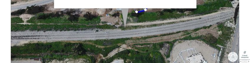
Saving Viewpoints

1. Use Saved Viewpoints to ‘bookmark’ an interesting viewpoint you wish to return to later
   in your session (saved viewpoints are cleared upon logout)
2. Click dropped pin icon to save a viewpoint, reclick to remove
3. Saved viewpoints are indexed and can be browsed through using arrows
Deliverables: 3D Pointcloud

1. 3D model that renders objects as a collection of colored points
2. Most suitable for performing measurements and analysis
3. Available for download in ‘.laz’ format (to be used in Recap…)
Deliverables: 3D Mesh

1. 3D model that renders objects as a network of solid triangles
2. Most suitable for visualization purposes ( no measurements available)
3. Available for download in ‘.obj’ format (with MTL file and texture)
Deliverables: 2D Orthophoto

1. High resolution map-like image of scan, scaled and georeferenced
2. Linked to 3D pointcloud: measurements placed in one, appear in the other
3. Overlay 2D plans in PDF format by selecting the ‘Overlay’ tool
4. Available for download in ‘.tif’ format (for import to CAD etc…)
Deliverables: Change Detection Analysis

1. 3D pointcloud with changes from previous scan highlighted (Green=Added, Red=Removed)
2. Use datepickers to select compared scans
3. Click raw image thumbnail to restore full size raw images of later scan
4. Additional comparisons are available upon request
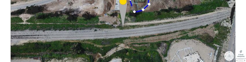
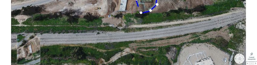
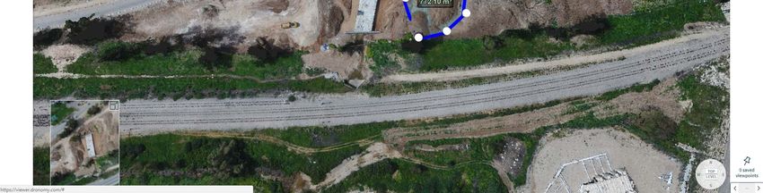
Measure Toolbox

1. Use Measure to perform on-screen measurements on pointclouds (inc. change detection) and
   orthophotos
2. Click user icon in top right corner to switch unit system: metric or imperial
3. Select Polyline for length,height and slope - select at least 2 points (zoom in for accuracy)
4. Select Polygon for area and volume - select at least 3 vertices
5. Measurements transfer between pointclouds and orthophotos
Measure Menu

1. Click on an existing measurement to open measure menu
2. Click eye icon to toggle polyline/polygon visibility (dimension label remains)
3. Click copy icon to duplicate measurement in a different scan date
4. Click notepad icon to add/edit measurement metadata
5. Measurements transfer between pointclouds and orthophotos
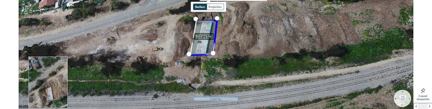
Measure Toolbox: Measuring Volumes

1. Using the Polygon tool, mark the outline of the object of interest (piles,excavations…)
2. In the Measure Menu, select Volume (height map may still be loading)
3. Select 1 of 4 options for reference plane (from which the volume measurement will be taken):
       Low- horizontal at lowest point, High – horizontal at highest point
       Best Fit – average elevation of all points with best fit slope
       Custom – user defined reference plane (elevation and slope) based on 4 points
Annotations Toolbox 1. Use Annotations to tag text, images,360 photos,videos and documents to points of interest 2. Annotations are added in 3 ways: manually, by import or by snapshot 3. Manage annotations by clicking ‘Please choose’ to open annotations table 4. Use search bar to search text fields within all annotations 5. Annotations can be used to assign tasks to other users or shared with CM software 6. 4 types of annotations can be created: Note, RFI, Punch Item and Photo
Manual Annotation Tool

1. Click ‘Add new’ button, cursor will switch to crosshair
2. Select point of interest to place annotation box, an entry is also added to the table
3. Annotation and viewpoint at which it was placed are indexed and can be recalled
4. Annotation dropped pin can be repositioned by dragging pin to new position (left click
   hold+drag)
‘Import’ Tool

1. Click ‘Import’ to create an annotation from images (or 360 photos)
2. A file explorer window will appear, from which one or more photos can be selected
3. Annotations with images attached will be created at the geotagged coordinates
4. Any non-geotagged images can be tagged manually by the user (by similar process to manual
   annotation)
5. Annotation dropped pin can be repositioned by dragging pin to new position (left click
   hold+drag)
Snapshot Tool

1. Click ‘Snapshot’ to capture the graphic window contents and create an annotation
2. Snapshots can be taken of any deliverable: pointcloud,mesh,orthophotos,or raw images
3. For pointcloud,mesh,orthophoto: the annotation is created with the coordinates of the
   viewpoint
4. For raw image: the annotation is created from the coordinates of the drone image
5. Annotation dropped pin can be repositioned by dragging pin to new position (left click
   hold+drag)
Annotation Box

1. The annotation box appears immediately after annotation is created
2. The annotation box contains a summary of the annotation data (title, text, media thumbnail)
3. The box can be repositioned by placing the cursor on the top bar and dragging
4. The top bar contains the color selector, expand and close commands
5. The bottom bar contains commands to approve changes, delete, share to 3rd party, and
   duplicate
Annotation Expanded View

1. Expanded view is accessed by clicking the expand button (    ) on the annotation box
2. Any attached media (image, 360 photo, video or pdf) appears in the center
3. Media tools appear below: rotate, scribble, add text, delete media, save, crop etc…
4. Use the navigation bar on top to browse between annotations in expanded view
5. Assigning annotations to users is done in the expanded view only via dropdown list
6. Clicking the media window or    button on bottom bar opens full screen mode
Annotations Table

1. The annotation table provides an overall view and managing of all annotations
2. Selecting annotations is done by marking the checkbox beside them
3. Annotations are hidden/displayed by clicking the eye icon for each annotation
4. Annotations can be filtered/sorted by: title, creator, assignee, creation date, scan date
5. Bulk action buttons are located at top left: open selected, assign selected,create annotation
   report,delete
6. Reset filters and close table buttons are located at top right
Duplicate Annotations/Measurements (Single View)

1. Any annotation or measurement can be duplicated to a different scan date in the same location
2. Duplicating is done by clicking the copy icon in the annotation or measurement menu
3. A window with a datepicker will appear from which the required scan date should be selected
4. Once the scan date is selected , it is loaded in the Location View, and the duplicated
   annotation/measurement appears
5. A duplicated measurement can be repositioned to compensate for any shifts between scans
Documents Folder

1. The documents folder acts as storage space for project documents (submittals, reports,
   specifications…)
2. Supports a wide variety of formats: MS Office files, PDFs, Gsuite files, Video, Images
3. Files can either be viewed in the viewer or downloaded
Overlay Toolbox (2D Ortho only)

1. Overlay 2D plans that have been uploaded to the Documents folder in PDF format
2. Select ‘Create’ to create a new overlay, ‘Load’ to select from existing, and ‘Unload’ to remove the
   overlay layer
3. Creating a new overlay is performed in 3 steps:
 I. Select 2 anchor points on the plan
 II. Identify and tag the anchors’ positions in the orthophoto
 III. Fine tune the alignment by dragging the anchors to their exact position
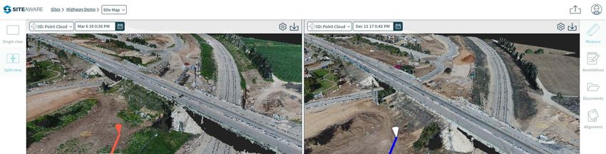
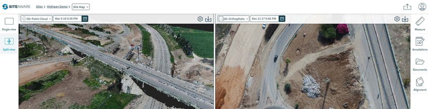
Split View mode

1. Used to display the results of a pair of deliverables(from any scan date) for the same location
2. Each side of the split view behaves like a Single View screen
3. For each side,use deliverable dropdown menu to select desired deliverable (3D mesh, 3D
   pointcloud, orthophoto, change detection analysis)
4. For each side,click calendar icon to open datepicker
5. By default, Split View is loaded with latest contents of Single View on the left side
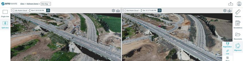
Alignment Toolbox (Split View)

1. Use Alignment to align deliverables that appear in both sides
2. ‘Registration’ initiates the manual alignment process (see next page for details)
3. ‘Link’ toggle is used to activate single controller mode: both scans will rotate,pan, zoom together
4. ‘Store’ saves the current alignment of a pair of deliverables for future use
5. ‘Reset’ restores latest stored alignment
6. ‘Auto Link’ restores the default alignment based on deliverable coordinates only
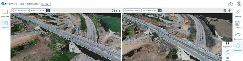
Registration tool (Split View)

1. ‘Registration’ tool enables alignment of deliverables created in different scans, the alignment is
   performed by selecting at least 3 point pairs in the active deliverables
2. Clicking ‘Registration’ will change the cursor to a crosshair, the 1st point should then be selected in
   one of the deliverables
3. Upon selection, the 1st point will be labeled and the registration menu will appear, after which the
   same point should be selected in the other deliverable
4. Repeat the point pair process at least 2 more times, the ‘Calculate’ button is enabled
5. Click ‘Calculate’ to align the deliverables, use Store tool to save for future use
Duplicate Annotations/Measurements (Split View)

1. Any annotation or measurement can be duplicated from one side to the other when different
   scan dates are selected
2. Duplicating is done by clicking the copy icon in the annotation or measurement menu
3. A duplicated measurement can be repositioned to compensate for any shifts between scans
Upload Page

1. Reached by clicking Upload icon (   ) in top right corner in any screen
2. Upload page open in a new tab (multiple tabs can be opened and are completed one by one)
3. Enter Scan name, select Site and Location from dropdown menus
4. Select scanned images or drag and drop to designated area
5. Select mission type: Area Single, Area Matrix, Structure Model,Structure Inspection ,Recon
6. Click Upload button
For further instructions see user manual or www.siteaware.com/support

       Alternatively, use tooltips to learn more about any button

          Feel free to contact us at : support@siteaware.com
You can also read