PORTABLE AIR CONDITIONER WITH HEATER - WA-9061H: 9,000 BTU WA-1061H: 10,000BTU Read and retain these instructions for future reference
←
→
Page content transcription
If your browser does not render page correctly, please read the page content below
PORTABLE AIR CONDITIONER WITH HEATER

                 WA-9061H: 9,000 BTU
                WA-1061H: 10,000BTU

☆ Read and retain these instructions for future reference
BEFORE USE
GENERAL SAFETY
• Only use in the upright position on a flat level
surface and at least 14in. from any walls or
objects (fig 1 & 4).
• Do not place any objects on the unit or block the
FIG. 1
air inlet / outlet (fig. 2).
• Closely supervise children and pets when unit is
in use.
ELECTRICAL SAFETY
• For indoor household use only.
• Switch off and unplug when not in use. FIG.2
• Do not use in humid or wet environments. (fig 3)
• Do not pull the UNIT by the cord.
• IF THE SUPPLY CORD IS DAMAGED, TO
AVOID HAZARD, IT MUST BE REPLACED BY
AN ELECTRICIAN OR SIMILARLY QUALIFIED
PERSON.
FOR MAXIMUM EFFICENCY
• Use the unit in the recommended room size. FIG.3
• Locate the unit where furniture cannot obstruct
the airflow.
• Close doors and windows.
• Keep curtains or blinds closed during the
sunniest part of the day.
• Keep filters clean.
• Set unit to maximum cooling on high initially and
once room has reached the desired conditions,
reduce temperature and fan speed settings.
• It is recommended to turn on the air conditioner
when ambient temperature reaches 75°F. Do
FIG.4
not wait until the room is excessively hot.
2PARTS
Front Back
FIG.5 FIG.6
1. Display window 6. Cord storage
2. Control panel 7. Air filter
3. Air outlet 8. Air inlet
4. Carrying handle 9. Exhaust air outlet
5. Caster 10. Air inlet
11. Water stopper/drainage
Accessories
FIG.7
13. Exhaust hose 17. Plastic slider kit – piece 2 of 3
14. Round Connector - for insertion over hose 18. Plastic slider kit – piece 3 of 3
and into window kit or through wall. 19. Drain tube
15. Cap for Round Connector 20. Active carbon filter
16. Plastic slider kit – piece 1 of 3 21. Remote
3INSTALLATION
The unit is a portable air conditioner that may be moved from room to room.
1. Installing the plastic slider kit.
Window kit
FIG.8
§ Remove the 4 screws around the circular opening on the plastic kit (#18).
§ Insert the round connector (#14) through the circular opening. The lip of the round
connector is on the flat side of the slider kit. Align the screw openings and replace the 4
screws.
§ Determine how many sections of the slider kit your window/sliding door requires.
§ Place slider kit inside the window/door frame, with flat side of round connector facing out.
§ Adjust the height of the slider kit, when the desired height is reached, insert a small
screw (not supplied) through the side opening to secure.
§ The best distance between the machine and window or wall is 31-39 inches.
2. Through the wall installation
Wall or Window
Outward adaptor
FIG.
9 FIG.10
• Cut a 5.39in diameter hole in the wall with height preferably leveled to unit’s air outlet.
• Feed exhaust hose through the wall opening and attach the Round Connector (#14) from
the outside as shown. You can secure the connector to wall with the 4 screws. (fig.10)
• When not in use, cover with Cap (#15).
4Mounting of the exhaust pipe
• Use only the hose provided and clip
exhaust hose to the back of the air
conditioner
• Avoid kinks and bends in the
exhaust hose. If expelled air is not
exhausted smoothly, it will build up
in the hose and lead to unit
overheating and shutting down.
Refer to Fig 11 & 12 for correct
position.
• The hose may be extended from 11”
to 59”. But for maximum efficiency,
use the shortest length possible.
WARNING!
The length of the exhaust pipe is
specially designed according to the
specification of this product. Do not
replace or prolong it with your own
private hose as this could cause the unit
to malfunction.
5Carbon Filter Installation
1. Remove filter frame from unit.
2. Remove the filter fixer from the filter frame.
3. Remove active carbon filter from plastic bag.
4. Insert active carbon filter to filter frame.
5. Replace filter fixer to frame. The active
carbon filter is now held in between the filter
frame and filter fixer.
6. Replace filter frame to unit.
6OPERATION
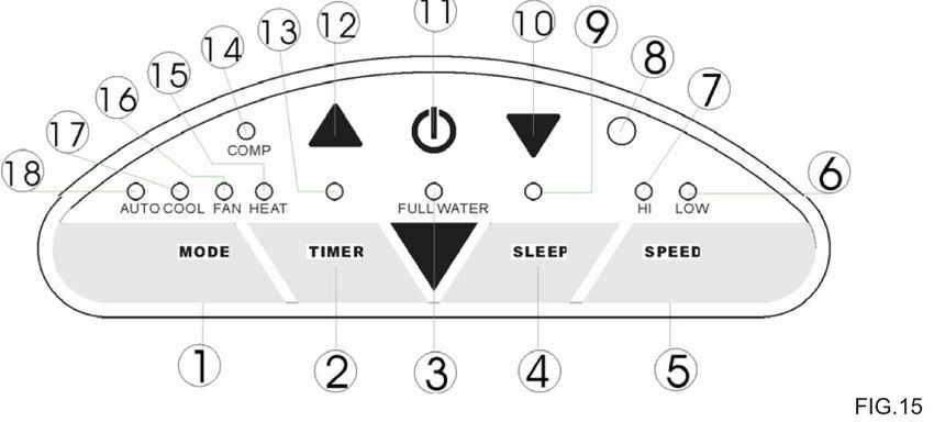
Control panel
1. Mode (function) select button 10. “Temperature down” button
2. Timer button 11. ON/OFF (power) button
3. “Water Full” indicator 12. “Temperature up” button
4. Sleep button 13. Timer operation indicator
5. Fan speed button 14. Compressor operation indicator
6. Low fan speed indicator 15. Heat mode indicator
7. High fan speed indicator 16. Fan mode indicator
8. Receiver for remote control 17. Cooling mode indicator
9. Sleep operation indicator 18. Auto mode indicator
Turning ON/OFF
1. Press ON/OFF button and unit will start automatically. If ambient temperature is:
§ Above 74°F/23°C, the unit will work in Cool mode.
§ Above 68°F/20°C but below or equal to 74°F/23°C , the unit will work in Fan mode.
§ Below 68°F/20°C, the unit will work in Heat mode.
2. Indicators of the functions in progress will illuminate.
NOTE: The display window shows ambient room temperature from 32~122°F/0~50oC.
3. To turn the unit off, press ON/OFF button again.
Setting mode/function
Press MODE button to select desired working mode: AUTO, COOL, FAN or HEAT.
The indicator of selected mode will illuminate.
7Setting temperature
1. Press 'Temperature up' or 'Temperature down' button to set desired temperature.
2. The display window will show the set temperature as the UP or DOWN buttons are pressed.
Once the buttons are release, display will revert to show the ambient temperature.
3. The pre-set temperature is 75°F/24°C for cooling and 68°F/20°C for heating.
Setting fan speed
1. Press SPEED button to choose the desired fan speed, high or low. The corresponding
indicator (HI or LOW) will illuminate.
2. If the unit is operating in AUTO mode, the SPEED button is invalid. Unit will automatically
choose the fan speed based on the ambient temperature.
Setting timer
1. If unit is in operation, pressing the TIMER button will set the operating hours (from 1 to 12
hours). Once the set time has been reached, unit will turn off automatically. Timer indicator
will illuminate. Display window shows the hour(s) as TIMER button is pressed.
2. If unit is off, pressing the TIMER button will pre-set the time for the unit to come on. For
example, if you set the timer to 2, the unit will begin operating after 2 hours.
Sleep function
1. When selected in COOL mode: unit will increase the set temperature by 2°F/1°C after the
first hour and another 2°F/1°C after the second hour, then keeps at that temperature.
2. When selected in HEAT mode: unit will decrease the set temperature by 2°F/1°C after the
first hour and another 2°F/1°C after the second hour, then keeps at that temperature.
3. In SLEEP mode, fan speed will be kept at LOW.
4. Pressing the SLEEP button again will revert set temperature and fan speed back to pre-
selected settings.
5. The unit will shut down automatically after operating in SLEEP mode for 12 hours
continuously.
NOTE: SLEEP function is not available in AUTO or FAN mode.
HEAT mode
1. When HEAT mode is selected, the ambient warm air will be recycled and utilized to heat the
area where it is required. The Exhaust Pipe must be fitted properly to exhaust the cold
air outdoors.
2. Continuous drain is mandatory when unit operates in heat mode.
3. The working temperature range for heating function is 45~77°F/7~25°C. If ambient
temperature is outside this range, the unit may not work properly.
8Remote control
All functions can also be performed with the supplied remote control.
The remote control requires two (2) AAA batteries.
Fig.16
Directing air flow
Manually adjust the louvers left & right or up & down to direct air
flow.
FIG. 17
NOTICE !
§ To prolong the life of the compressor, after powering off the unit, please wait at least 3
minutes before turning it back on.
§ When operating in COOL mode, the cooling system will switch off when ambient temperature
falls below set temperature. The fan, however, will continue to run. Once ambient
temperature rises above the selected level, cooling will resume.
§ When operating in HEAT mode, heating will switch off when ambient temperature is higher
than set temperature. The fan, however, will continue to run. Once ambient temperature
drops below the selected level, heating will resume.
§ This machine is equipped with ANTI-FROST function. When unit is operating in low
temperature surroundings, the heating function may be paused at times to defrost. When this
occurs, just wait for heating to resume.
9DRAINAGE
During the cooling process, some water will be extracted from the air into the unit.
If the reservoir is full, both of the compressor (cooling) and motor (fan) will stop and unit will emit
a Buzz (press any button to stop the buzz); the Water Full indicator will also be flashing.
Before cooling can resume, empty the water tank:
1. Turn off the air conditioner and avoid moving it when full.
2. Position a container (a water tray for example)
underneath the drain spout.
3. Remove the drain knob & rubber plug and allow water to
drain out.
4. When the container is almost full, replace the rubber plug
and empty the water tray. Repeat until the unit is emptied.
5. Replace rubber plug and tighten drain knob firmly.
6. Switch on the unit – the Water Full indicator should no
longer be flashing.
Continuous drainage (if you wish to operate the unit without the need to empty the water tank):
• Remove the drain knob and rubber plug and retain
for future use.
• Connect the supplied drain tube to the drain spout
as shown and locate the other end into a drain.
• Note the drainage is gravity-pulled, the drain tube
must not have any incline.
• The drain tube can be extended by adding an
extension tube with a suitable connector.
Note
• Drain tube must be paralleled or below outlet level.
• Flashing ‘Water Full’ indicator will not function in
continuous drainage.
• To extend the water tube, connect with another
tube (OD: 18mm)
10MAINTENANCE
Always unplug the air conditioner from power source before cleaning.
Clean regularly to maximize the efficiency of the air conditioner.
Cleaning the housing
§ Use a soft, damp cloth to wipe the body clean.
§ Never use aggressive chemicals, gasoline, detergents, chemically treated cloths, or other
cleansing solutions. These products may blemish the cabinet.
Cleaning the filter
§ Use a vacuum cleaner or tap the filter lightly to first remove any loose particles, then rinse
thoroughly under running water (no hotter than 104°F/40°C).
§ Dry thoroughly before replacing.
§ Never operate the unit without the filters.
End of season storage
• Drain water from the unit.
• Operate the unit in FAN mode for a few hours to
thoroughly dry the inside.
• Clean or change the filters.
• Unplug and store the power cord as shown.
• Replace in the original carton or cover for storage.
TROUBLE SHOOTING
§ Is the air conditioner plugged in?
The air conditioner does not § Is there a power failure?
run § Is the Water Full indicator flashing?
§ Is the room temperature below the set temperature?
§ Is there direct sunshine? (Please close curtain)
The machine seems to do § Too many windows or doors open?
little § Too many people in the room?
§ Is there something in the room producing lots of heat?
§ Is the filter dusty, contaminated?
The machine seems to do
§ Is the air intake or output blocked up?
nothing.
§ Is the room temperature below set temperature?
§ Is the machine positioned unevenly, creating vibration?
Too noisy
§ Is the floor underneath the machine uneven?
§ It is possible the overheat protection is on. Just wait for
The compressor doesn’t run.
the temperature to drop.
☆ Never try to repair or dismantle the unit yourself
11Your Guarantee
If this product is found to be faulty as a result of faulty materials or workmanship
within one year from date of purchase, it will be repaired free of charge.
This guarantee is subject to the following terms:
• Sunpentown must be notified of the fault.
• Proof of purchase must be presented to Sunpentown’s nominated representative.
• The warranty will be void if the product if modified, misused or repaired by an unauthorized
person.
• The warranty after repair will not be extended beyond the original one-year period.
• All replacement parts will be new or reconditioned.
• Parts, which are replaced, become the property of Sunpentown.
• The warranty applies for the use of the product in the USA only.
What is NOT COVERED:
• Warranty does not include freight charges.
• Incidental or consequential damage caused by possible defects with this product.
• Damage to product caused by improper power supply voltage, accident, fire, floods or acts of
nature.
• Failure of product resulting from unauthorized modifications to the product.
• Improper installation or failure to perform the necessary maintenance.
This GUARANTEE is in addition to your Statutory Rights
SUNPENTOWN INTERNATIONAL INC.
14625 Clark Ave. City of Industry, CA 91745
Tel: 800-330-0388
service@sunpentown.com
www.sunpentown.com
12You can also read