Design and Implementation of Ultrafast Broadband Sweep Source based on AD9914
←
→
Page content transcription
If your browser does not render page correctly, please read the page content below

Journal of Physics: Conference Series

PAPER • OPEN ACCESS

Design and Implementation of Ultrafast Broadband Sweep Source based
on AD9914
To cite this article: Kaida Cai et al 2021 J. Phys.: Conf. Ser. 1820 012062

View the article online for updates and enhancements.

 This content was downloaded from IP address 46.4.80.155 on 21/04/2021 at 01:54
MEMAT 2021 IOP Publishing
Journal of Physics: Conference Series 1820 (2021) 012062 doi:10.1088/1742-6596/1820/1/012062

Design and Implementation of Ultrafast Broadband Sweep
Source based on AD9914

 Cai Kaida, Zhang Zhongyang, Huang Qingchun, Xiao Jing*
 School of Mechanical and Electrical Engineering, Guilin University of Electronic
 Technology, Guilin, 541000, China
 Corresponding author and e-mail: Xiao Jing, xiaojing@guet.edu.cn

 Abstract. To address a technical difficulty of long scanning cycle of broadband (100
 MHz~900 MHz) frequency sweep source, an ultrafast broadband sweep source was designed
 based on the basic principle of direct digital-frequency synthesis (DDS) theory by using the
 high-performance DDS chip AD9914. During the design, the DSP28335 chip was used as the
 control device. The designed source can output 100MHz~900 MHz swept-frequency signals
 and it can realize sawtooth wave frequency-modulated signals in the shortest cycle (8us) by
 configuring the digital ramp generator in the chip. Moreover, a microstrip stepped impedance
 low-pass filter was designed using ADS to eliminate spurious signals in the direct synthesizer
 and decrease the in-band attenuation, thus making the curve flatter. According to final test and
 experimental data analysis, the designed sweep source has a large output broadband, short
 sweeping cycle and strong inhibition of spurious signals. It possesses great application values.

1. Introduction
Recent studies on radar system focus on the radar range system based on frequency modulation
continuous wave (FMCW). FMCW radar is a radar that transmits stable linear frequency continuous
wave radio, receives reflected signals from objects and measures range and speed of objects through
the beat signal between two signals[1]. FMCW generator is an essential component in the FMCW radar
system. According to theoretical knowledge of FMCW radar system, the range resolution of linear
frequency modulation (FM) radar is determined by sweep bandwidth of transmitted signals. Linearity
of transmitting source influences range measurement error of the linear FM radar. At present,
associated studies mainly focus on low frequency resolution, low-phase noise, fast frequency
switching and high sweep linearity. Direct digital-frequency synthesis (DDS), the third generation of
frequency synthesis technology, can realize very high frequency resolution, FM linearity and sweeping
speed [2,3]. Moreover, the improving integrated circuit manufacturing techniques provide a powerful
guarantee to development of DDS chips with higher output frequency and they have been widely
applied in range measurement system of FMCW radar. In this study, a high-performance ultrafast
broadband DDS sweep source was designed by combining AD9914 and DSP28335. The output
frequency range of the designed DDS is 100MHz~900 MHz. The designed source realizes faster
sweeping and shortens sweeping cycle by configuring a digital ramp generator (DRG). Moreover, a
microstrip stepped impedance low-pass filter with excellent performances was designed to solve
spurious signals of DDC. A further comprehensive analysis was carried out based on the simulation
results of this low-pass filter and practical test data, indicating that the designed sweep source has
stable outputs and few spurious signals. It can meet expectations in view of all parameters[4].

 Content from this work may be used under the terms of the Creative Commons Attribution 3.0 licence. Any further distribution
 of this work must maintain attribution to the author(s) and the title of the work, journal citation and DOI.
Published under licence by IOP Publishing Ltd 1
MEMAT 2021 IOP Publishing
Journal of Physics: Conference Series 1820 (2021) 012062 doi:10.1088/1742-6596/1820/1/012062

2. Design of altrafast broadband sweep source

2.1. Device selection
The designed DDS circuit is based on the direct digital-frequency synthesis chip AD9914 (ADI) and it
supports single frequency point output and linear sweeping output. The AD9914 integrates 12-bit
DAC. The highest reference clock frequency of AD9914 reaches 3.5GHz and its output frequency
range is DC~1.4 GHz. AD9914 takes the dominant role in term of phase noise performances and
inhibition of spurious signals within the industry [5]. It supports five working mode, including single-
frequency, Profile modulation, linear sweeping, parallel data port modulation and programmable
modulation. According to the design needs, the single-frequency mode can generate single-frequency
signals and linear sweeping mode can generate linear FM signals. In the single-frequency mode, signal
control parameters of DDS are provided by the Profile programming register directly. In the linear
sweeping mode, signal control parameters of DDS are provided by the DRG and the ramp direction
(slope of the linear FM signal) is controlled externally by DRCTL pin.
 Nowadays, the mainstream TMS320 series DSP includes C2000, C5000 and C6000 series.
Different series have different advantages and application platforms. Among them, the C5000 series
DSP is designed exclusively for the consumption-oriented digital market and it emphasizes on
arithmetic speed and low power consumption. The C5000 series DSP is mainly applied to portable
products. However, the C5000 series DSP products are all 16-bit fixed point type, which is
inconvenient for floating-point arithmetic programming. The C6000 series show the strongest
handling capacity and they are mainly used to image processing, network exchange, etc. However, the
C6000 series have excessive power consumption and package due to the strong performances.
Compared to C5000 series and C6000 series, the C2000 series consider the balance between
performance and power consumption and they are characteristic of high precision, high speed and low
power consumption. Therefore, the C2000 series DSP28335 of TI Company was used in design of
signal source controller, which could meet the design needs of this system better.

2.2. Overall framework of the system
The whole system circuits include the minimum system circuit of DSP28335, circuit of AD9914 chip,
linear power circuit and low-pass filter circuit. The overall framework of system is shown in Fig.1.

 Fig.1 Overall framework of the system

 The DSP28335 chip was used as the control unit and the compiled program was downloaded to
DSP28335 through a PC. The DSP28335 controls the AD9914 chip through a SPI. The linear power
circuit supplies powers to both DSP28335 and AD9914 chip simultaneously. Based on the
collaborative control of system clock and DSP28335, AD9914 outputs the ideal frequency signals
after the low-pass filter circuit.

2.3. Connection between DSP28335 and DDS chip
Frequency control word has two input modes, namely, serial input and parallel input. According to
practical needs, the serial input was chosen in this study. The connection between DSP28335 and
AD9914 is shown in Fig.2.

 2
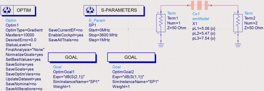
MEMAT 2021 IOP Publishing
Journal of Physics: Conference Series 1820 (2021) 012062 doi:10.1088/1742-6596/1820/1/012062

 CS, SCLK and SDIO are serial I/O ports of AD9914. Among them, CS is chip selection signal,
SCLK is serial clock, and SDIO is serial data input/output port. The DSP28335 configures the internal
memory of AD9914 and controls signal output of AD9914 through serial ports. The
MASTER_RESET is the reset port of the master of AD9914 and it is for reset all memory elements.
The register is set at the default. IO_UPDATE is used to transmit I/O buffer contents to effective
internal memories. Since the written data only stays in the serial porter buffer and it is invalid, the
register can only be configured effectively through I/O updating. PS0, PS1 and PS2 are optional pins
of the PROFILE register. The sixteen PROFILE registers in AD9914 were chosen by setting high and
low levels of these three pins.

 Fig.2 Connections between DSP28335 and AD9914

2.4. Calculation of microstrip line-related data of microstrip stepped impedance low-pass filter
Since the composite signal generated by DDS technology directly contain a lot of spurious signals,
which are mainly caused by error accumulation, including phase truncation, quantification of range
and digital-to-analogue conversion [6], the composite signal has to be filtered. The passband frequency
of the designed low-pass filter is ranged between 100MHz-900MHz. The attenuation in the passband
frequency range is lower than 0.8dB, and the attenuation at 1800MHz is higher than 40dB. The system
characteristic impedance is 50Ω. With respect to material selection, the minimum and maximum
characteristic impedances of the microstrip line were chosen 15Ω and 130Ω, respectively. Moreover,
thickness and relative dielectric constant of the substrate of microstrip line were 1.27mm and 4.2,
respectively. In this study, the 5-order Chebyshev low-pass filter was chosen as the prototype in the
design.
 The schematic diagram was built using the ADS software and the microstrip line was calculated by
LineCalc. Firstly, width and length of the microstrip line with a characteristic impedance of 15Ω were
calculated firstly. After parameters were set in LineCalc (Fig.3), it could calculate that the width is
W=12.09mm. According to values of elements of the low-pass prototype filter and the calculation
formula of characteristic impedance of the low-impedance line , it can get that the length
is L=5.06mm. Widths of the rest transmission lines were calculated continuously by LineCalc.
Therefore, the 5-order microstrip line data is listed in Table 1.

 Fig.3 Calculated results of microstrip line in the LineCalc window

 3
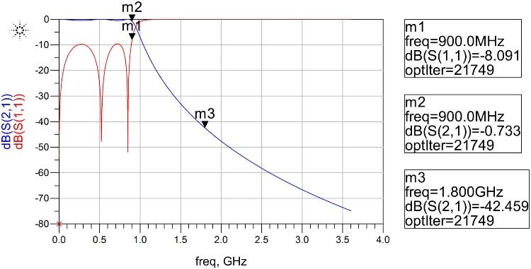
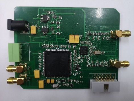
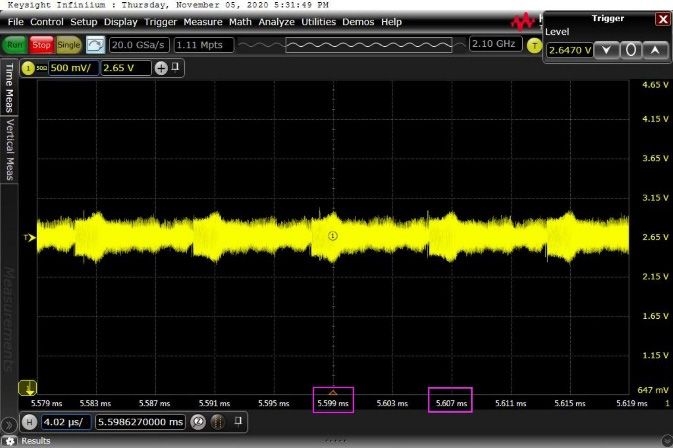
MEMAT 2021 IOP Publishing
Journal of Physics: Conference Series 1820 (2021) 012062 doi:10.1088/1742-6596/1820/1/012062

 Table 1 Sizes of microstrip line

3. ADS circuit simulation
Fig.4 shows that VAR and Optim/Stat/DOE were recalled in the layout diagram and parameters were
set for optimization simulation. S parameter simulation was performed after finishing the simulation.
S11 and S21 are shown in Fig.5.

 Fig.4 Optimized layout diagram

 Fig.5 Optimization simulation results of layout diagram

 It can be seen from Fig.5 that the S11 is -8.091dB at 900MHz . S21 is -0.733dB at 900MHz and -
42.459dB at 1800MHz. These meet requirements of technological indexes.

4. Experimental test results
The physical picture of circuits is shown in Fig.6. Internal DRG of AD9914 was configured through
DSP28335 and DDS circuit was set as a sawtooth wave sweeping mode. The sweeping range was 100
MHz ~900 MHz. Signal sweeping waveform was output by an oscilloscope and results are shown in
Fig.7. The sweeping cycle was 8us, accompanied with decreasing in-band attenuation and flat curves.
Moreover, the sweeping cycle of DDS can be determined by using an oscilloscope to test level change
period of indicator pin (DROVER) at the end of sweeping of AD9914 chip. The testing results at the
shortest sweeping cycle (8us) are shown in Fig.8.

 4
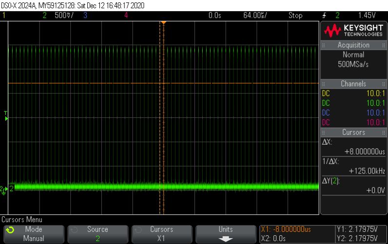
MEMAT 2021 IOP Publishing
Journal of Physics: Conference Series 1820 (2021) 012062 doi:10.1088/1742-6596/1820/1/012062

 Fig.6 Physical picture of control circuit

 Fig.7 Sweeping range of DDS (100 MHz ~900 MHz)

 Fig.8 Sweeping time of DDS (8us @100 MHz ~900 MHz)

5. Conclusions
A broadband sweep source (100MHz ~ 900MHz) is designed based on AD9914 of DDS chip and it
realizes sawtooth linear FM in the shortest sweeping cycle (8us) by configuring DRG in the chip. The
output is flat and has a good inhibition of spurious signals. The shortest sweeping cycle of measured
output signal can be equal to reference value of the chip data manual.

 5
MEMAT 2021 IOP Publishing
Journal of Physics: Conference Series 1820 (2021) 012062 doi:10.1088/1742-6596/1820/1/012062

Acknowledgment
This work was supported by National Natural Science Foundation of China (No.61764002), Guangxi
Natural Science Foundation (No.2017GXNSFAA198282), the Innovation Project of GUET Graduate
Education(No.2019YCXS003), and the Study Abroad Program for graduate student of Guilin
University of Electronic Technology (No.GDYX2019007).

Author information
Cai Kaida:Master Student. Research Direction: research and design of a wide range ranging system
based on FMCW modulation.
 Zhang Zhongyang: Undergraduate Student. Research Direction: research and design of a wide
range ranging system based on FMCW modulation.
 Huang Qingchun: Master Student. Research Direction: research and design of millimeter wave
radar ranging system.
 Xiao Jing: Associate Professor. Research Direction: integration and packaging technology of
heterogeneous optoelectronic devices, integration test based on FMCW.

References
[1] Dudek, M., Kissinger, D., Weigel, R., et al. (2011) Consideration of higher frequency bands in
 accurate millimeter-wave FMCW-radar system simulations for automotive application. In:
 IEEE Wireless and Microwave Technology. Clearwater Beach. pp.1-4.
[2] Tierney, J., Rader, C., and Gold, B. (2003) A digital frequency synthesizer. IEEE Transactions on
 Audio and Electroacoustics., 19,1: 48-57.
[3] Baek, T.J., Ko, D.S. (2011) A Transceiver Module for FMCW Radar Sensors Using 94-GHz Dot-
 Type Schottky Diode Mixer. IEEE SENSORS JOURNAL., 11,2: 370-376.
[4] Wang Q. (2019) Design and implementation of signal generator based on AD9914.
 Communication Technology., 52,9: 2304-2309.
[5] Sheng Y.F., Liu Z.Q., Wang W.B., et al. (2018) Broadband low phase noise DDS frequency source
 based on AD9914. In: 2018 National Microwave and Millimeter Wave. Chengdu. pp.61-64.
[6] Zhao L., Qi Q., Zhang J. (2015) Signal Generation Method Based on High Speed DDS Chip
 AD9914. Radar and confrontation., 4: 29-32.

 6
You can also read