2021 E-CALIBER SERVICE MANUAL SUPPLEMENT - Rev 1 June 2021
←
→
Page content transcription
If your browser does not render page correctly, please read the page content below

2021 E-CALIBER
SERVICE MANUAL SUPPLEMENT
                Rev 1 June 2021
2021 E-Caliber Service Manual

Contents
Safety                                               1
Headset with Knock Block                             2
Frame and drive system guards                        3
Rear triangle and chainstay bridge                   4
Main pivot                                           6
Derailleur hanger                                    7
Cabling overview                                     8
IsoStrut remote lockout cable                        9
IsoStrut                                            10
Air volume spacer                                   11
Carriage wiper seals and bushings                   14
Drive system                                        19
Specifications                                      20
Suspension                                          21

Safety
        WARNING
Always tighten hardware to the specified torque.
Over-tightening hardware could deform or break the
hardware or components. Under-tightening hardware
could cause hardware or components to become loose.
Either situation could damage the bicycle and result in
injury to the rider.

        WARNING
All reused-fasteners with pre-applied threadlocker must
be cleaned with isopropyl alcohol and have new thread-
locker applied before re-assembly. If threadlocker is not
applied, the fasteners may loosen which could damage
the bicycle and result in injury to the rider.

                               Copyright 2021 Trek Bicycle Corporation All Rights Reserved

                                                                                                                         1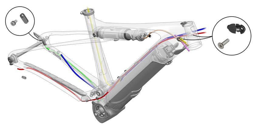
2021 E-Caliber Service Manual

Headset with Knock Block
                                                                            1
                                                         2
                                                         3
                                                                           4

                                                                            5

                                                                            6
                                                                               7

                                                                                   Quantity in
 Item         Description                                                          Assembly Part Number         Torque (Nm)
     1       Upper bearing cover                                                       1                             —
     2       Knock Block chip bolt                                                     1                             2
     3       Knock Block chip, 62 degrees                                              1         5252159             —
     4       Compression ring                                                          1                             —
     5       Upper bearing                                                             1                             —
     6       Lower bearing                                                             1                             —
                                                                                                  5252158
     7       Crown race                                                                1                             —

Tools                                                              6.   Install the upper bearing (5), then the compression
          •   2.5mm hex tool                                            ring (4) onto the steerer tube.
          •   Torque wrench with 2.5mm hex bit                     7.   Insert the Knock Block chip (3) and bolt (2) into the
          •   Headset tools                                             frame, but do not tighten it.
          •   Grease
                                                                   8.   Install the upper bearing cover (1).
1.        Inspect the components for damage or excessive
          wear.                                                    9.   Install spacers as needed.

          • Knock Block chip (3)                                   10. Torque the Knock Block chip bolt (2) to 2Nm.
          • Underside channel of the upper bearing cover (1)
          • Interlocking keys of the upper bearing cover (1)
            and the stem
2.        Replace any damaged or worn components.

3.             Apply grease to:
          • Upper and lower head tube bearing bores.
          • Inside of the bearing seats of the compression
            ring (4) and the crown race (7).
4.        Install the crown race (7), then the lower bearing (6)
          onto the steerer tube.
5.        Insert the steerer tube into the bottom of the head
          tube.

                                                                                                                                2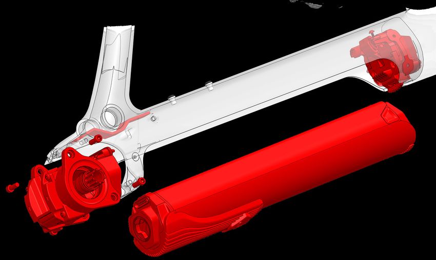
2021 E-Caliber Service Manual

Frame and drive system guards

                                                                                  2

                         1

                                                             3

                                            3

                                                  4

                                                                 Quantity in
  Item    Description                                            Assembly      Part Number     Torque (Nm)
    1    Chainstay guard                                            1         W582883              —
    2    Down tube guard                                            1         W582884              —
    3    Drive unit guard fasteners                                 4         5269023              3
    4    Drive unit guard                                           1         W1040440             —

Chainstay and down tube guards
Use isopropyl alcohol to clean the frame surface where the
guards attach. Wait for the alcohol to dry before applying
the guards.

Notice: Do not clean the entire frame with isopropyl
alcohol. Isopropyl alcohol could damage the paint.

                                                                                                             3
2021 E-Caliber Service Manual

Rear triangle and chainstay bridge

                                                                              4

                                                                                                                           5

       1                                                                                                                  4
                                             2

                                                             3

                                                                                  Quantity in
     Item      Description                                                        Assembly       Part Number    Torque (Nm)
      1       Rear IsoStrut axle                                                     1          591626              10
      2       End cap bolt                                                           1                               —
      3       Front IsoStrut bolt and washer                                         2          W584485              5
      4       Chainstay bridge bolt                                                  4          5265697              8
      5       Chainstay bridge, charcoal color                                       1          5266755              —

Tools                                                            3.   Install the two front IsoStrut bolts and washers (3).
           • Bike repair stand
           • Torque wrench with 6mm hex bit, T25 and T30
             Torx bits
           • Grease
Important: You must have the main pivot bearing and
sleeve (See the Main pivot section on page 6) and the
IsoStrut (See the IsoStrut section on page 10) installed
on the rear triangle before attaching the rear triangle to
the frame.                                                            Important: Do not torque the bolts at this time.

1.         Put the seatpost in a bike repair stand.              4.        Apply grease to the IsoStrut rear axle (1).

2.         Fit the rear triangle into the main frame.
                                                                 5.   Install the IsoStrut rear axle (1) and end cap bolt (2).
                                                                      Important: Do not torque the bolts at this time.
                                                                 6.        Apply grease to the flat surfaces of the chainstay
                                                                           bridge (5).

                                                                                                                               4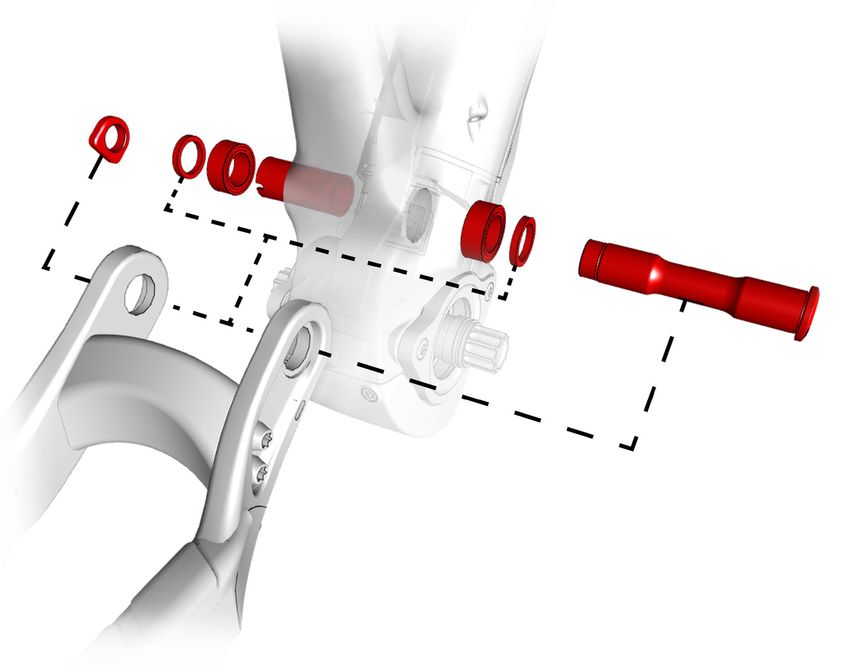
2021 E-Caliber Service Manual

Rear triangle and chainstay bridge (continued)
7.   Insert the chainstay bridge (5) inside the rear
     triangle.

                                            5
          4

                                                       4

8.   Install the four bridge bolts (4) to attach the bridge to
     the rear triangle.
9.   If applicable, install the main pivot hardware before
     torquing the bridge bolts (4).  See the Main pivot
     section on page 6.
10. Torque:
     • Chainstay bridge bolts (4) to 8Nm.
     • IsoStrut rear axle (1) to 10Nm.
     • Front IsoStrut bolts (3) to 5Nm.

                                                                                             5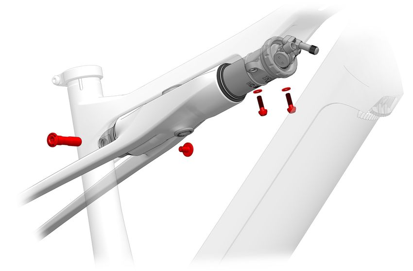
2021 E-Caliber Service Manual

Main pivot
                                                2
                                                    3
                                                        4
                                   1
                                                                            3
                                                                                 2
                                                                                               5

 Item         Description                                                            Quantity in    Part Number    Torque (Nm)
                                                                                     Assembly
     1       Main pivot nut                                                             1            W584134           —
     2       Washer                                                                     2            W440921           —
     3       Main pivot bearing                                                         2           W302025            —
     4       Main pivot sleeve                                                          1           W600642            —
     5       Main pivot bolt                                                            1           W600628           30

Tools                                                               8.   Insert the non-driveside washer (2) bewtween the
          •   Bearing press                                              bearing the chainstay.
          •   8mm hex tool                                          9.   Fully insert the main pivot bolt (5).
          •   Torque wrench with 8mm hex bit                        10. Install the nut (1).
          •   Grease
                                                                    11. Torque the main pivot bolt (5) to 30Nm.
1.        Press in the driveside bearing (3).
2.        Insert the sleeve (4) from the non-drive side.
3.        Press-in the non-driveside bearing (3).
4.        Position the chainstay over the seat tube, making
          sure the main pivot holes are aligned.
          Tip: Slide the long arm of the hex tool from the non-
          drive side and through the aligned pivot holes. For
          each step, slide the component onto the hex tool to
          align the components on each side of the main pivot.

5.             Apply grease to the shoulder of the main pivot
               bolt (5).
6.        Insert the driveside washer (2) between the bearing
          the chainstay.
7.        Partially insert the main pivot bolt (5) from the drive
          side.

                                                                                                                                 6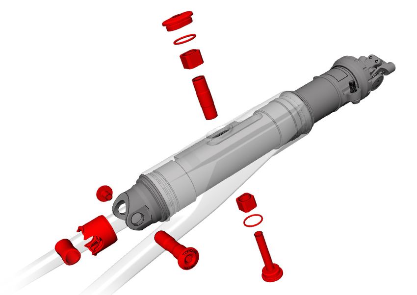
2021 E-Caliber Service Manual

Derailleur hanger

                                               1

                                                               2

 Item        Description                                                          Quantity in Part Number       Torque (Nm)
                                                                                  Assembly
     1      Thru axle, M12X1.0X15MM                                                   1         W600321             10
     2      Derailleur hanger                                                         1                              —
             Hanger bolt, left-handed thread                                           1         W600660             25
             Washer, 25mm                                                              1                              —

This bicycle frame is designed to use a Universal Derailleur       4.   Make sure the hanger is positioned as shown below.
Hanger (UDH).
 NOTICE: The thru axle must be compatible with a UDH
 and must be M12x1.0 with a 12.7mm thread.
 NOTICE: The washer is frame-specific. Install only the
 washer compatible with your frame.

             WARNING
 Do not apply grease to the derailleur hanger or bolt.
 Apply grease to only the thru axle.
                                                                   5.   Torque the hanger bolt to 25Nm.

1.        Insert the hanger on the inside of the driveside         NOTICE: Do not over-tighten. Over-tightening the bolt
          chainstay.                                               could cause the hanger to break.
2.        Install the washer on the derailleur hanger bolt.
                                                                   For additional information about the UDH, refer to the
3.        Insert the bolt into the frame.                          SRAM user manual at sram.com.

                                                                                                                              7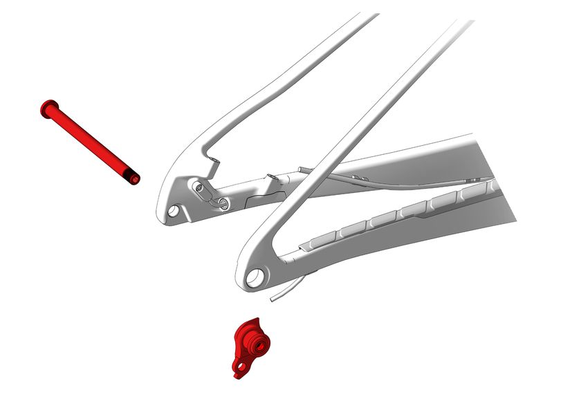
2021 E-Caliber Service Manual
Cabling overview
1 2 5
6 7
3
4
8
9
12
11 10
Item Description Quantity in Part Number Torque (Nm)
Assembly
1 Bolt 1 W562831 3
2 Speed sensor 1 W581396 —
3 Rear brake cable 1 — —
4 Speed sensor cable 1 — —
5 Dropper post cable 1 — —
6 IsoStrut lockout cable 1 — —
7 Head tube cable guide 2 W519232 —
8 Head tube cable guide fastener 2 W532763 1
9 Controller cable 1 — —
10 Down tube cable guide 3 W591416 —
11 Rear derailleur cable 1 — —
12 Grommet, for use with wireless derailleur only 1 5259425 —
Zip tie location 4 — —
Route and zip tie the cables as shown in the illustration above.
Dropper cable IsoStrut cable
• For detailed dropper remote instructions, please refer • See the IsoStrut remote lockout cable section on
to the Drop Lock Remote manual at trekbikes.com/ page 9.
manuals.
8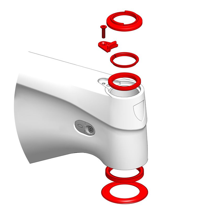
2021 E-Caliber Service Manual

IsoStrut remote lockout cable
Tools                                                          5.   Guide the wire through the slot in the cable stop.
     • Cable cutter
     • Torque wrench with 2mm hex bit
1.   Install the cable in the remote lockout.
2.   Route the cable through the hole in the bottom of the
     top tube just forward of the IsoStrut and out the drive
     side of the head tube hole.

                                                               6.   Route the wire around the lockout spool and install
                                                                    the set screw. Torque to 1Nm.

3.   At the head tube, route the wire through the cable.

                                                                           Drive side                Non-drive side

                                                               7.   Test that the mechanism works satisfactorily.
                                                               8.   Cut the wire to the appropriate length (20-30mm)
                                                                    and crimp an end cap on it.

4.   At the IsoStrut, slide the ferrule on the wire.

                                                                                                                          9
2021 E-Caliber Service Manual
IsoStrut
1 6
2
3
4
9
8
3
7 2
5
10
Item Description Quantity in Part Number Torque (Nm)
Assembly
1 Damper body nut 1 —
2 O-ring 2 —
3 Guide bushing 2 W580727 —
4 Damper body sleeve 1 —
5 Damper body bolt 1 7
6 Fox shock, performance, black 1 W587198 —
Fox shock, performance, kashima W587197 —
7 Compression sleeve 1 591626 —
8 Shock oil plug 1 W580727
9 End cap bolt 1 591626 —
10 Rear IsoStrut axle 1 10
Tools 3. Install the upper guide bushing (3) into the carriage.
• Torque wrench with 5mm hex bit
1. Assemble the body bolt (5), body sleeve (4), one
o-ring (2) and one guide bushing (3) as shown below.
4. Install the o-ring (2) onto the damper body nut (1).
2. Insert the assembly into the bottom of the carriage.
5. Install damper body nut (1) with o-ring (2) into the
carriage.
6. Torque the damper body bolt (5) to 7Nm.
102021 E-Caliber Service Manual
Air volume spacer
Item Description Part Number
1 Fox air volume spacer kit 595583
Tools Release the shock from the carriage
• BSA30 Open-ended bottom bracket tool 1. Remove the two bolts and washers at the front of the
• Spanner pliers shock.
• Loctite Blue 243 threadlocker or similar
• Parallel jaws pliers
• T25 torx drive wrench
• Torque wrench
• Shock pump
• Spacers
• Soft cloth
• Grease
Note: This procedure should be performed with the
IsoStrut installed on the bike.
Note the current air pressure
2. Loosen, but DO NOT REMOVE the rear axle.
1. Use a shock pump to check the air pressure in the
shock. Make a note of the current air pressure so you 3. Turn the lockout lever counter-clockwise to the open/
can re-inflate the shock after changing the air spacer. unlocked position.
2. Gradually bleed the air from the air valve.
Tip: You do not need to compress the shock because
you will need some air in the negative air spring.
112021 E-Caliber Service Manual
Air volume spacer (continued)
4. Sit on the seat to compress the suspension. The front Replace the air spacer
of the IsoStrut will move away from the top tube to
provide clearance for the BSA30 wrench. 1. Clean off any dirt or residue from the threads and the
lock ring.
5. Position your body on the seat to keep the shock
2. Move the round metal plate toward the o-ring. Use a
compressed, and use the BSA30 wrench to break the
spanner pliers to remove the air volume spacer.
lock ring loose and unthread it from the carriage.
NOTICE: Use a soft cloth to protect the top tube
from scratches the BSA30 wrench may cause.
3. Put a new spacer in place around the damper shaft.
6. Once the ring is unthreaded from the shock, the front Tip: Depending on the size of the spacer, it may be
end of the shock will extend forward to reveal an helpful to use the spanner pliers or a parallel jaws
o-ring, a round metal plate, and the air spacer. pliers to fit the spacer in place.
1 2 3
4. You should hear a ‘snap’ when the spacer snaps into
Item Description
the front end of the shock.
1 O-ring
2 Round metal plate
3 Air spacer
122021 E-Caliber Service Manual
Air volume spacer (continued)
Size medium, large and extra large frames: the
Tighten the lockring cable hanger aligns with the mounting tab.
1. Add Loctite Blue 243 threadlocker or similar to
a minimum of 2 threads covering 60-90°of
threads.
5. Place the torque wrench in the hole in the BSA30
wrench. Torque the lock ring to 17Nm.
2. Stand behind the seat and pull the seat up to extend
the suspension. This will bring the lock ring in contact
with the strut.
6. Verify the shock is positioned to accept a shock
pump to the air valve. If there is interference, reposi-
tion the shock.
3. Use the BSA30 wrench to turn the lock ring onto the
strut.
Tip: For best results, sit on the rear tire for this step
to balance the bike.
7. Install the washers and bolts at the front of the
shock. Torque the bolts to 5Nm.
8. Torque the rear shock axle to 10Nm.
4. As you tighten the lock ring, orient the upper air cap 9. Use the shock pump to re-inflate the shock air pres-
as shown below. sure to the PSI noted prior to beginning the air spacer
Size small frame: the air fill valve aligns with the procedure.
mounting tab. 10. Perform the sag procedure to determine the proper
rider setting for the strut.
132021 E-Caliber Service Manual
Carriage wiper seals and bushings
1
4
2
3
2
1
3
Quantity in
Item Description Assembly Part Number Kit
1 Carriage wiper seal 2 — 592550
2 Carriage wiper bushing 2 595247
3 Foam block 2 —
4 Foam ring 1 —
Tools for replacing the seals Remove the shock from the carriage
• IsoStrut seal and bushing press tool set. Available 1. Remove the IsoStrut hardware. See IsoStrut section
as part number 593490. on page 10.
• Delrin rod, 1 inch (25.4mm)
• Headset press 2. Remove the shock from the carriage.
• Fork bath oil, 10wt
Tools for replacing the bushings
• Slide hammer
• 30-36 Expanding collet
• IsoStrut seal and bushing press tool set. Available
as part number 593490
• Bushing sizer
• Clean, dry cloth
NOTICE: Inspect all tools prior to use to make sure
they are clean. Dirty tools could deposit grit into
the shock which could mar surfaces and create
friction that could damage the shock.
142021 E-Caliber Service Manual
Carriage wiper seals and bushings (continued)
Remove the carriage seals Replace the bushings
1. Use the Delrin rod to pull out the front seal. NOTICE: Do not apply grease to the bushings.
Tip: You may need to move the rod around the car-
riage to remove the seal. 1. Put the slide hammer with the collet attached inside
the front end of the carriage.
NOTICE: Take care to engage only the bushing,
and NOT the interior of the carriage. Engaging the
carriage could damage the carriage.
2. Pull out the foam ring. This is the only foam ring in the
carriage.
2. Thread the collet to engage the bushing lip.
Tip: Be careful not to engage the lip inside the car-
riage. Engage the bushing only.
3. Use the Delrin rod to pull out the rear seal.
3. Use the slide hammer to remove the bushing.
If you are replacing only the seals, jump to Carriage wiper
seals and bushings (continued) section on page 17. 4. Repeat steps 1–3 to remove the rear bushing.
If you are replacing both the seals and the bushings, con- 5. Wipe the bushing bores with a clean, dry cloth to
tinue with the Replace the bushings section on page 15. remove any debris.
152021 E-Caliber Service Manual
Carriage wiper seals and bushings (continued)
6. Load a new bushing onto each bushing installation 10. Spin the headset press until it is snug against the
tool. bushing tool. Check for correct alignment of the
press, tools, and bushings. Rotate the press to push
Bushing the bushings into place. It’s normal to have different
Use this side of the tool for pressing in gaps at the front and rear of the carriage.
bushings.
Seal
Use this side of the tool for pressing in
seals.
NOTICE: Do not use grease when installing the 11. Tighten the press until you feel resistance. Once you
bushings. Using grease could cause the bushings feel resistance, remove the press and both tools.
to slip out of place. 12. Inspect the bushings to verify they are pressed deep
enough into the carriage. From the top of the bushing
7. Put one tool with one bushing into the front of the to the step above the bushing, the measurements
carriage, and the other tool with the other bushing should be:
into the rear of the carriage.
Front = 16.9mm Rear = 10.5mm
8. Insert the upper half of the headset press into the
front of the carriage.
13. From the front of the carriage, use the bushing sizer
to size the bushing. The sizer can be rotated to the
left or to the right.
9. Insert the lower half of the headset press into the
rear end of the carriage and lock it into place.
14. Repeat step 13 three to four times, alternating be-
tween the front and rear bushings.
162021 E-Caliber Service Manual
Carriage wiper seals and bushings (continued)
Replace the wiper seals 6. Spin the headset press until it is snug against the
seal tool. Check for correct alignment of the press,
1. Wipe the seal surface inside the carriage to remove tools, and seals. Rotate the press to push the seals
debris. into place.
2. Load a new seal onto each seal installation tool.
Seal
Use this side of the tool for pressing in
seals.
Bushing 7. Tighten the press until you feel resistance. Once you
Use this side of the tool for pressing in feel resistance, remove the press and tools.
bushings.
8. Inspect the seals to verify there is no gap between
the seal and the carriage.
3. Put one tool with one seal into the front of the car-
riage, and the other tool with the other seal into the
rear of the carriage.
4. Insert the upper half of the headset press into the
front of the carriage. 9. Soak the foam ring in 10wt fork bath oil.
10. Install the foam ring into the front of the carriage.
5. Insert the lower half of the headset press into the
rear end of the carriage and lock it into place.
172021 E-Caliber Service Manual
Carriage wiper seals and bushings (continued)
Install the IsoStrut into the carriage Install the damper body hardware
1. Remove the compression sleeve. See IsoStrut section on page 10.
2. Carefully pull out the oil plug from the shock. Add oil to the carriage
1. Use a syringe to fill the IsoStrut with 15cc of 10wt oil.
3. Place the foam blocks into the carriage and position
them against the sides of the carriage. Do not soak
2. Firmly press the oil plug back into the aft end of the
the foam blocks in fork bath oil prior to installation.
shock. Make sure the plug is tightly seated in the
4. Lightly oil the inside of the carriage seals. opening.
3. Install the compression sleeve into the oil plug.
5. With the sag o-ring in place on the shock, insert the
shock into the carriage.
4. Install the IsoStrut rear axle and end cap nut. Torque
the axle to 10Nm.
Tip: If the compression sleeve will not allow the rear
IsoStrut hardware to pass through, the oil plug is not
fully seated into the shock. (See step 2.)
5. Install the front IsoStrut washers and bolts. Torque
the bolts to 5Nm.
6. Wipe off any excess oil from the IsoStrut.
182021 E-Caliber Service Manual
Drive system
2
1 3
3
1
Quantity in
Item Description Assembly Part Number Torque (Nm) Notes
1 Bottom bracket fastener 4 8 – 8.5 Frame thread must
2 Locker fastener 4 Refer to the 2021 Domane+ LT 1.8 – 2.2 be clean. Do not apply
Fazua system manual. grease.
3 Spider lockring 1 20 – 25
192021 E-Caliber Service Manual
Specifications
Chainline (1x only)
Knock Block steering radius
62 degrees
52-55mm Seatpost
Minimum insertion
WARNING
Always follow the seatpost manufacturer’s minimum
insertion recommendation. Failure to follow the recom-
Chainring (1x only) mendation could cause damage to the seatpost which
Minimum 30T could cause the rider to fall and become injured.
Maximum 32T with 52mm chainline
36T with 55mm chainline Maximum insertion
Frame size Maximum
Insertion
Small frame 205mm
Rear brake rotor
Medium 270mm
Minimum 180mm direct mount
Large
Maximum 230mm
Extra large
202021 E-Caliber Service Manual
Suspension
The first step in suspension setup is to set the sag. All other settings should be adjusted after setting the sag.
For instructions on how to set the sag, please view the Suspension setup video at trekbikes.com/manuals.
Refer to the suspension setup card included with your bike or the online suspension calculator at
trekbikes.com/suspension-calculator.
For recommended rebound settings refer to the suspension calculator at trekbikes.com/suspension-calculator.
IsoStrut
• Recommended sag: 20-25%
1
2
3 4
Item Description Dimension
1 Shock eye-to-eye length 235mm
2 Stroke length 32.5mm
3 Rear mount width 31mm
4 Front mount width 48mm
Fork
WARNING
Maximum fork length is measured axle to crown.
Exceeding the recommended maximum fork length could
damage the bicycle and could cause severe injury to the
rider.
3
2
1
Item Description Dimension
1 Recommended sag 18mm /15%
2 Travel 120mm
3 Maximum fork length 531mm
21You can also read