MICRO 4 CHANNEL HDMI LIVE STREAM MULTI-FORMAT VIDEO SWITCHER - cvc.de
←
→
Page content transcription
If your browser does not render page correctly, please read the page content below
MICRO 4 CHANNEL HDMI LIVE STREAM MULTI-FORMAT VIDEO SWITCHER
USING THE UNIT SAFELY
Before using this unit, please read below warning and precautions which provide important information
concerning the proper operation of the unit. Besides, to assure that you have gained a good grasp of
every feature of your new unit, read below manual. This manual should be saved and kept on hand for
further convenient reference.

          Warning And Cautions

※ To avoid falling or damage, please do not place this unit on an unstable cart, stand, or table.

※ Operate unit only on the specified supply voltage.

※ Disconnect power cord by connector only. Do not pull on cable portion.

※ Do not place or drop heavy or sharp-edged objects on power cord. A damaged cord can cause fire or
electrical shock hazards. Regularly check power cord for excessive wear or damage to avoid possible fire
/ electrical hazards.

※ Ensure unit is properly grounded at all times to prevent electrical shock hazard.

※ Do not operate unit in hazardous or potentially explosive atmospheres. Doing so could result in fire,
explosion, or other dangerous results.

※ Do not use this unit in or near water.

※ Do not allow liquids, metal pieces, or other foreign materials to enter the unit.

※ Handle with care to avoid shocks in transit. Shocks may cause malfunction. When you need to
transport the unit, use the original packing materials or alternate adequate packing.

※ Do not remove covers, panels, casing, or access circuitry with power applied to the unit! Turn power off
and disconnect power cord prior to removal. Internal servicing / adjustment of unit should only be
performed by qualified personnel.

※ Turn off the unit if an abnormality or malfunction occurs. Disconnect everything before moving the unit.

Note: due to constant effort to improve products and product features, specifications may change without
notice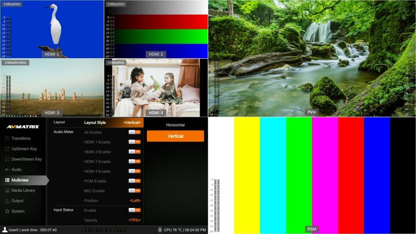
CONTENTS
1. BRIEF INTRODUCTION.............................................................................................................................. 1

1.1. Overview...................................................................................................................................................... 1

1.2. Main Features............................................................................................................................................. 1

2. INTERFACES.................................................................................................................................................2

2.1. Interface Overview......................................................................................................................................2

2.2. Tally PIN Definition.....................................................................................................................................2

3. SPECIFICATION........................................................................................................................................... 3

4. FRONT CONTROL PANEL.........................................................................................................................4

5. POWER ON/ OFF..........................................................................................................................................5

6. MULTIVIEW....................................................................................................................................................6

6.1. Status Page................................................................................................................................................. 6

6.2. Layouts.........................................................................................................................................................7

6.3. Audio Meter................................................................................................................................................. 8

6.4. Input Information......................................................................................................................................... 8

6.5. UMD Settings.............................................................................................................................................. 9

7. PGM PVW SWITCHING.............................................................................................................................10

7.1. PGM PVW Channel Selection................................................................................................................ 10

7.2. STILL.......................................................................................................................................................... 11

7.3. Transition: CUT/ AUTO/ T-BAR............................................................................................................. 11

8. TRANSITION EFFECT............................................................................................................................... 11

8.1. WIPE...........................................................................................................................................................11

8.2. DIP.............................................................................................................................................................. 12

8.3. MIX..............................................................................................................................................................12

8.4. Transition Speed Setting......................................................................................................................... 12

9. UPSTREAM KEY........................................................................................................................................ 13

9.1. Luma Key...................................................................................................................................................13

9.2. Chroma key............................................................................................................................................... 14

9.3. PIP & POP................................................................................................................................................. 16

10. DOWNSTREAM KEY............................................................................................................................... 17

10.1. DSK.......................................................................................................................................................... 17
10.2. LOGO....................................................................................................................................................... 18

11. OUTPUT SETTING................................................................................................................................... 19

11.1. Output Interfaces.................................................................................................................................... 19

11.2. Multiview Out...........................................................................................................................................19

11.3. PGM Out.................................................................................................................................................. 20

11.4. USB Out...................................................................................................................................................20

11.5. Output Format Setting........................................................................................................................... 21

11.6. FTB........................................................................................................................................................... 21

12. AUDIO SETTING.......................................................................................................................................22

12.1. Master Audio........................................................................................................................................... 22

12.2. Audio On (MIX)....................................................................................................................................... 22

12.3. AFV...........................................................................................................................................................23

12.4. Audio Delay............................................................................................................................................. 23

12.5. MIC........................................................................................................................................................... 23

12.6. Earphone................................................................................................................................................. 23

12.7. Audio Keyboard Configuration............................................................................................................. 24

12.8. Mute..........................................................................................................................................................25

13. MEDIA LIBRARY...................................................................................................................................... 25

13.1. PVW Pattern & PGM Pattern................................................................................................................25

13.2. User-defined Color Pattern................................................................................................................... 25

13.3. Image Setting.......................................................................................................................................... 26

14. SYSTEM SETTING................................................................................................................................... 27

14.1. Language.................................................................................................................................................27

14.2. Fan Setting.............................................................................................................................................. 27

14.3. System Reset..........................................................................................................................................28

14.4. Download.................................................................................................................................................28

14.5. Version..................................................................................................................................................... 28

14.6. Time Setting............................................................................................................................................ 28

14.7. Network Setting...................................................................................................................................... 28

14.8. User Setting.............................................................................................................................................29
1. BRIEF INTRODUCTION
1.1. Overview
HVS0402U is a 4-channel HDMI multi-format video Switcher with compact metal case design. It supports
various functions including video switching, audio mixing, PGM/ multiview/ Aux out, different transition
effects, Luma Key Chroma Key, DSK, LOGO, PIP/ POP, media library, pattern and color generator, etc.
Inputs support multi-format, PGM output can be scaled, compatible with a variety of equipment. The unit
supports stream performances and presentations on PC through the USB-C port. User can also
customize different settings and import or export the configuration quickly for various scenarios. It’s a
powerful and professional video switcher for your choices.
1.2. Main Features
4 channel auto-detected HDMI inputs
1×HDMI PGM output,1×HDMI multiview out, 1×USB type-C output
AUX output configurable and assignable
USB-C for capturing and streaming on PC
Clearly visible multiview & status page
Upstream key: Luma key, Chroma key, PIP×2/ POP
Downstream key and LOGO overlay
T-bar/ Auto/ Cut transitions; various effects: WIPE(9×2 patterns) / MIX/ DIP
Audio mixer: HDMI embedded audio and 2-Ch MIC/ line In; audio delay available
Media library: 49 default patterns, 16 imported images, 16 captured images, 2 color generators
LAN port for PC software remote control
Customer configuration import and export
FTB/ MUTE/ STILL/ GPIO for tally
1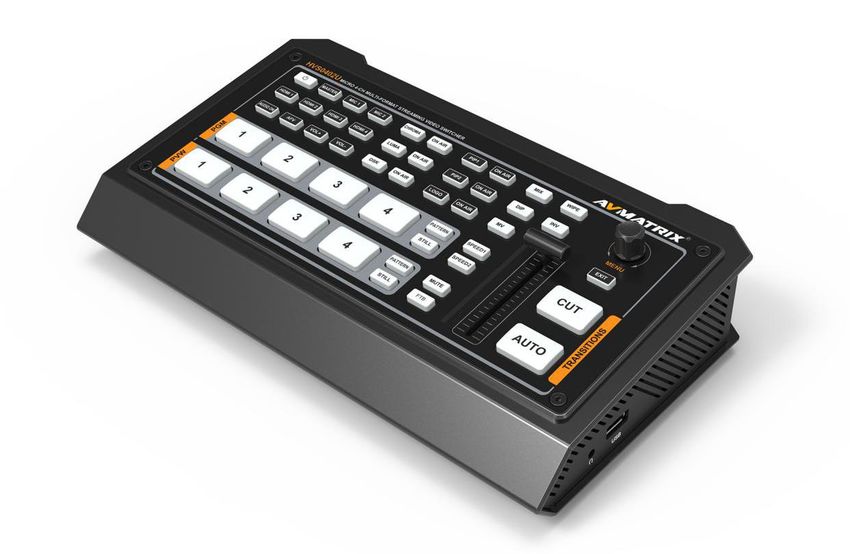
2. INTERFACES
2.1. Interface Overview

   1     MIC/Line level IN × 2
   2     HDMI IN × 4
   3     MULTIVIEW(AUX) OUT × 1
   4     PGM(AUX) OUT × 1
   5     USB OUT × 1 (for live streaming on PC)
   6     LAN port for PC software control
   7     GPIO (for tally)
   8     DC 12V IN × 1
   9     Earphone OUT × 1
   10    USB type-A × 1 (insert U disk to import images and LOGO; firmware upgrade)

2.2. Tally PIN Definition

   PIN                      Definition              PIN                   Definition
    11                      PGM-IN1                  6                    PVW-IN1
    12                      PGM-IN2                  7                    PVW-IN2
    13                      PGM-IN3                  8                    PVW-IN3
    14                      PGM-IN4                  9                    PVW-IN4
    15                         NC                    10                      NC
    3                          NC                    4                       NC
    5                         GND

                                              2
3. SPECIFICATION
CONNECTION

Video In             HDMI type-A ×4
                     HDMI type-A PGM ×1
                     HDMI type-A Multiview ×1
Video Out
                     USB2.0 type C ×1 (Streaming on PC)
                     Assignable HDMI 1~4, PGM, Clean PGM, PVW, Color bar, Multiview
Audio In             MIC/ Line level (3.5mm stereo audio) ×2
PC Control Port      LAN×1
Media Library        USB type-A ×1(USB disk port for image import and firmware upgrade)
Tally Port           DB-15 ×1
Power In             DC 12V ×1
FUNCTIONS

Transitions          T-Bar/AUTO/ CUT
Effects              Wipe (9×2 patterns)/ Mix/ DIP/ Pattern/ Still(freeze)/ MUTE/ FTB
Layouts              2 styles of Multiview layout (6 windows and status)
                     Upstream Key: Luma Key ×1/ Chroma Key ×1/ PiP ×2/ POP
Keys
                     Downstream Key: DSK ×1/ Logo ×1
                     HDMI ×4 and MIC/ Line level ×2;
Audio Mixer
                     Audio delay: 0-500ms
                     Default image: 49 preset patterns
Media                Local image: up to 16 imported images
                     Capture image: up to 16 captured images
                     Pattern generator ×1
Generators
                     Color generators ×2
STANDARDS

                     1080p 60/ 59.94/ 50/ 30/ 29.97/ 25/ 24/ 23.98
HDMI In Format       1080i 50/ 59.94/ 60
Support              720p 60/ 59.94 /50/ 30/ 29.97/ 25/ 24/ 23.98
                     576i 50, 576p 50, 480p 59.94/ 60, 480i 59.94/ 60
HDMI PGM Out         1080p 60/ 59.94/ 50/ 48/ 47.95/ 30/ 29.97/ 25/ 24/ 23.98; 1080i 60/ 59.94/ 50
HDMI Multiview Out   1080p 60/ 59.94/ 50/ 48/ 47.95/ 30/ 29.97/ 25/ 24/ 23.98; 1080i 60/ 59.94/ 50
HDMI Color Space     RGB/ YUV
USB Capture Out      MJPG, Up to 1080p 60
Media Format         USB disk format support: FAT32, Ext3, Ext4, up to 256GB

                                                3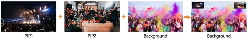
Image format support: png, bmp, jpg, gif, jpeg, ppm, pbm, tif, jps, mpo, tga
                        Logo format support: png, bmp, jpg, gif, jpeg, ppm, pbm, tif, jps, mpo, tga
                        Logo size support: 10×10 pixel to 600×600 pixel
OTHERS

Power                   Wide voltage: 7~24V; Operating power:12W (12V 1A)
Dimension (LWD)         244.5 × 143.2 × 44.5mm
Weight                  Net: 1030g; Gross: 1500g
Temperature             Working: -20℃~60℃, Storage: -30℃~70℃
Accessories             Power supply (12V 2A) ×1; USB cable (type A-C) ×1; Tally connector (DB-15) ×1

4. FRONT CONTROL PANEL

  1           Power
                            Press the power to start the device; Press 3s to shut down the system

                            Selecting the signal source for Program.

                            PATTERN for setting a pattern to PGM, STILL for freezing the input source.
  2           PGM:1-4
                            Note: different patterns can be set including Black/Color Bar/Color1

                            /Color2/ HDMI In1/HDMI In2/HDMI In3/HDMI In4/Image. (Refers to Part
                            13.1)

                            Selecting the signal source for Preview.
  3           PVW:1-4
                            PATTERN for setting a pattern to PVW (Refers to Part 13.1), STILL for
                            freezing the input source (Refers to Part 7.2).

                                                   4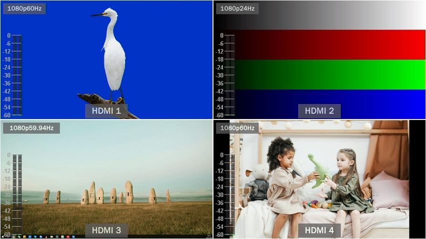
4      AUDIO       User can configure the audio of each channel in this area, including AFV or
                    audio mix mode, audio source selecting, adjust volume + & volume -

 5       DSK        DSK: Enable the downstream key

                    ON AIR: make the DSK on air

                    CHROMA:      Enable the Chroma Key

                    LUMA: Enable the Chroma Key
      CHROMA KEY
 6                  PIP1/PIP2: Enable two group of Picture in Picture. Size and position can be
       LUMA KEY     set via Menu.

                    LOGO: Add logo bin from USB flash disk, enable the logo overlay

                    ON AIR: make the corresponding Chroma/Luma/PIP/Logo on air.

 7       MV         MV: quickly switch between Multiview and the configured multiview out

                    (Refers to Part 11.2)

                    WIPE: Transition from one source to another
       Transition   INV: Invert the direction of selected wipe transition
 8
        Effects
                    MIX: Selects a basic A/B dissolve for the next transition

                    DIP: Gradual transition that transitions from one source to another.
 9       MENU
                    MENU: For menu control, configure different parameter

 10    CUT/ AUTO    CUT: Performs a simple immediate switch between Program and Preview.

                    AUTO: Performs an automated switch between Program and Preview.
 11      T-Bar
                    Switch the PVW and PGM through T-Bar

 12    MUTE/ FTB    MUTE: Mute the master audio

                    FTB: Fade to Black, used for emergency.
 13     SPEED
                    SPEED1-2: Control transition rate, speed can be configured on Menu.

5. POWER ON/ OFF
                         Connect your video sources and the output devices, plug the power
                         adapter. Press the power button in the front panel to get the video
                         switcher start to work.

                         Press the power button for about 3 seconds when you want to power
                         off the switcher, select YES in the prompt box to shut down the system.

                                            5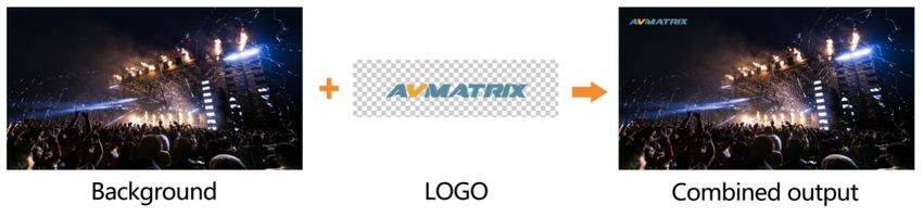
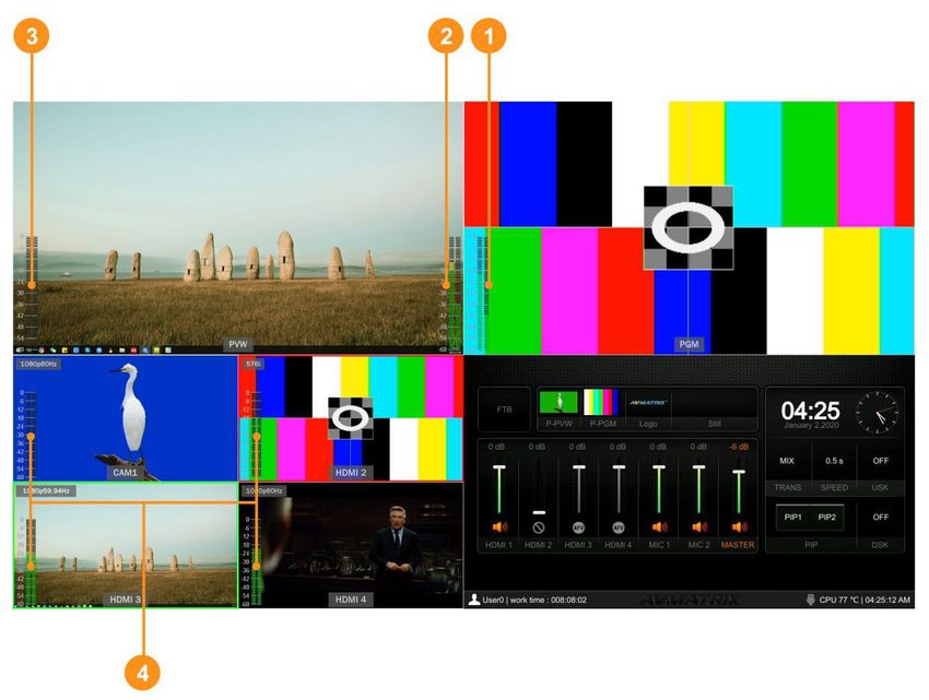
6. MULTIVIEW
The switcher has two HDMI outputs (PGM/Multiview). The two HDMI ports are both the AUX out that user
can define it as output of HDMI 1/ HDMI 2/ HDMI 3/ HDMI 4/ PGM/ Clean PGM/ PVW/ Color Bar/
Multiview (Refer to part 11). Connecting the HDMI Multiview out to an additional monitor, user will get the
multiview image. In the Multiview there are windows of PVW, PGM, HDMI 1, HDMI 2, HDMI 3, HDMI4 and
Status/Menu page. See below image.

6.1. Status Page
In the status page, there are status information of FTB (Fade to Black), P-PVW (Pattern in PVW row),
P-PGM (Pattern in PGM row), Logo, Still, Audio, Transition Effect, Transition Speed, USK (UpstreamKey),
DSK (DownstreamKey), and System Time. See below image.

                                                    6
The information of user name, working time, USB connection, CPU working temperature, system time
keeps displaying in the bottom of the Status/Menu page.
The information on the status page will be updated in real time as the settings changed. It’s clear and
visible for user to know the current situation and settings.
Pressing menu button of the switcher, the status page will go to the menu page. See below image.
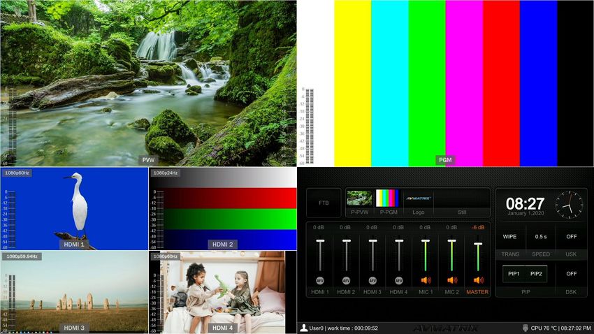
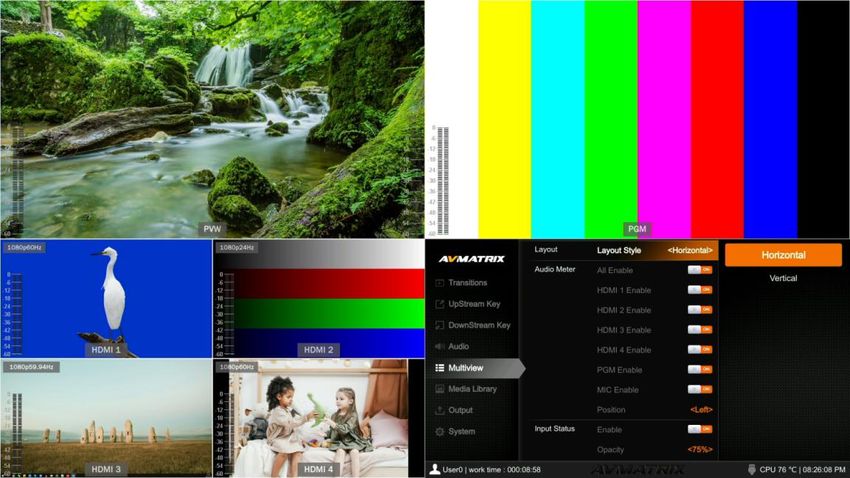
6.2. Layouts
There are two Multiview layouts which can be switch between the horizontal layout and vertical layout
from menu as below images.
- Horizontal layout:
7- Vertical Layout:
6.3. Audio Meter
There are audio meters in each windows of Multiview, including HDMI1-4, PGM and MIC to show the
audio status of each audio. The audio meters of MIC 1 and MIC 2 show in the left and right of PVW
window. User can turn on/ off All or each audio meter from the menu. The audio meter position can be in
the right or left of each window. See below image.
MIC1 Master Audio
MIC2
HDMI 1-4 Audio
6.4. Input Information
There is an overlay in each window of the HDMI 1-4. The overlay shows the resolution and frame rate of
8HDMI input. User can turn on/off overlay in each input window. Besides, user can set the overlay Opacity
(50%, 75%, 100%), Size (Small/Medium/Large), Position X & Y (1-100), Text color and Background Color.
See below image.
6.5. UMD Settings
The default UMD of the four inputs are HDMI1, HDMI2, HDMI3, HDMI4. User can turn on/off the UMD in
each window. Besides, user can set the overlay Opacity (50%, 75%, 100%), Size (Small/Medium/Large),
Position X & Y (1-100), Text color and Background Color. See below image.
9The UMD string content for 4 HDMI inputs can be set from menu. User can rename the UMD content for
each window by using a virtual keyboard and rotary button. It supports input max 10 characters for the
UMD content. Below image as an example, rename the HDMI 1 to CAM1.
7. PGM PVW SWITCHING
7.1. PGM PVW Channel Selection
Choose PGM and PVW source from PGM, PVW row and PATTERN (different pattern can be configured
on menu, refers to Part 13.1) in the front panel. The selected button for PGM will turn on to red LED, and
the selected button for PVW will turn on to green LED. The PGM source will be circled with red border,
while the PVW source will be circled with green border.
107.2. STILL
The video switcher supports STILL function, which user can freeze the input sources. Press the channel
you want to freeze in the PGM or PVW row, then press the STILL button to make the input source freeze.
User can freeze all the four inputs if they need. Press the input channel and STILL again to unfreeze.
7.3. Transition: CUT/ AUTO/ T-BAR
There are two transition control types for this video switcher: Transition without effects (CUT) and
Transition with effects (AUTO, T-Bar).
CUT performs a simple immediate switch between Preview and Program. This is no delay seamless
switching and the selected transition effect WIPE, MIX or DIP is not used.
AUTO performs an automated switch between Preview and Program views. The timing of the transition
can be set by speed button. The transition effects WIPE, DIP, MIX will also be used.
T-BAR manual transition performs similar to AUTO, but it is more flexible that the timing of the transition
depends on the speed of the manual switch.
8. TRANSITION EFFECT
The video switcher provides various transition effects and types for user’s choice, including WIPE, DIP,
MIX.
8.1. WIPE
Press the WIPE button to perform the wipe transition effect. User can choose different style of WIPE
through menu; as well as set the softness of edge. Select the direction from Normal/ Invert/ Flip-Flop
when use AUTO transition.
11Press the INV button to invert the selected wipe so it acts in the opposite direction.
8.2. DIP
Press the DIP button to perform the DIP transition effect. User can select the various color for DIP from
the palette on menu. The default color is black.
DIP to Black (fade out):
DIP to White (fade out):
8.3. MIX
Press the MIX button to perform the MIX transition effect.
8.4. Transition Speed Setting
User can set two speed of transition on menu, and the defined speed value will be saved and
corresponds to Speed 1 and Speed 2 button. The higher value, the slower the transition speed, total
0.1s-8.0s for choice.
129. UPSTREAM KEY
Upstream Key essentially means that these are keys that are included as part of the transition, so in the
transition from whatever on Preview to Program, anything that's an Upstream key is going to be
transitioned with it.
9.1. Luma Key
Key Source = Fill Source
Key Source ≠ Fill Source
Luma keys provide a way to composite a Text clip over a background clip based on the luminance levels
in the video. Turn on the Luma Key, a color from the key source will be removed, revealing another
background image behind it.
Switching a video with background to PVW window, and turn on the Luma Key. Press the menu knob to
enter the setting interface. Under Luma Key seb-menu, user can assign the fill and key source from
various options including Black/ Color Bar/ Color1/ Color 2/ HDMI 1/ HDMI 2/ HDMI 3/ HDMI 4/ Image
(import from USB disk). Configure and adjust the Key parameters including Clip/Gain/mask to achieve
the effect needed.
Press ON AIR button, the ON AIR button will be on, and the Key effect will show on PGM.
LUMA button ON: Luma key shows on PVW
ON AIR button ON: Luma Key available on PGM
LUMA and ON AIR button both ON: Luma Key available on both PVW and PGM. Corresponding status in
menu is
Luma key menu interface and parameter setting as below:
13Menu Sub-menu Item Parameter Default
Luma Status OFF/ KEY (PVW)/ ON AIR (PGM)/ KEY & ON AIR OFF
Black/ Color Bar/ Color 1/ Color 2/ HDMI 1/ HDMI
Fill Source Color1
2/ HDMI 3/ HDMI 4/ Image
Black/ Color Bar/ Color 1/ Color 2/ HDMI 1/ HDMI
Key Source Image
2/ HDMI 3/ HDMI 4/ Image
Clip 0%-100% 10%
Gain 0%-100% 0%
Upstream Key Luma Key
Invert Key On/Off Off
Mask Enable On/Off Off
Mask Left 0%-100% 0%
Mask Top 0%-100% 0%
Mask Right 0%-100% 50%
Mask Bottom 0%-100% 50%
Clip: Adjust the threshold at which the key cuts its hole. When decrease the clip degree, more of the
background will appear. If the background video is completely black then the clip value is too low.
Gain: Adjusts the performance of the chroma key in light or white areas. Apply more Key Gain if the light
areas are becoming too transparent.
Invert Key: Inverts the key signal.
Mask: Configure the Mask for the Key area
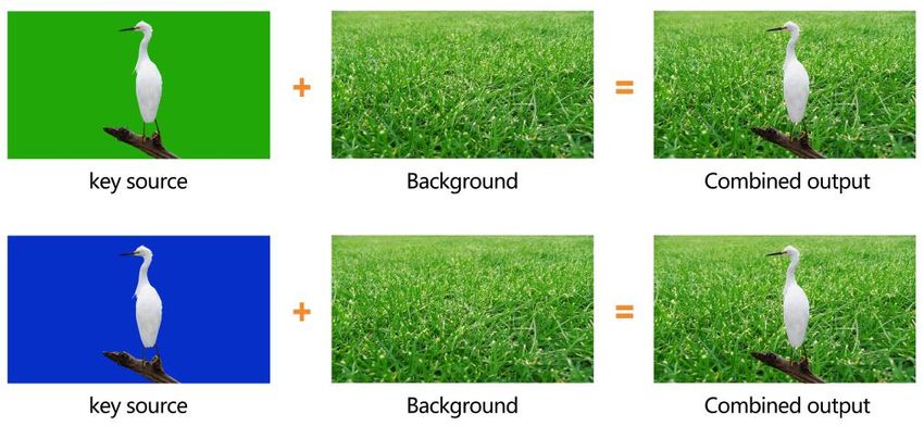
9.2. Chroma key
Chroma Key is a visual-effects and post-production technique for compositing (layering)
14two images or video streams together based on color hues (chroma range). The technique has been
used in many fields to remove a background from the subject of a photo or video, particularly
the newscasting, motion picture, and video game industries.
User can configure the effect of Chroma Key, including the key source, Key color, Clip, Gain, key Fetch
and mask, etc. in the menu page.
Press the ON AIR button next to the CHROMA button to enable the KEY on PGM.
CHROMA button ON: Chroma key shows on PVW.
ON AIR button ON: Chroma Key available on PGM
CHROMA and ON AIR button both ON: Chroma Key available on both PVW and PGM. Corresponding
status in menu is
Chroma Key detailed parameters setting as below table:
Menu Sub-menu Item Parameter Default
OFF/ KEY (PVW)/ ON AIR (PGM)/ KEY
Chroma Status OFF
& ON AIR
Black/ Color Bar/ Color 1/ Color 2/ HDMI
Key Source Image
1/ HDMI 2/ HDMI 3/ HDMI 4/ Image
Key Color R 0~255 0
Key Color G 0~255 255
Key Color B 0~255 0
Fetch Color 0
Upstream Key Chroma Key
Fetch Width 0~50% 5
Clip 0%-100% 40%
Gain 0%-100% 10%
Mask Enable On/Off Off
Mask Left 0%-100% 0%
Mask Top 0%-100% 0%
Mask Right 0%-100% 50%
Mask Bottom 0%-100% 50%
159.3. PIP & POP
The video switcher supports two groups PIP or one POP. When press PIP1 or PIP2 button, there will be a
small image display on the top left corner of PVW window. Press the Menu knob and choose the PIP
setting interface, user can set parameters including position, size, border etc. Press ON AIR button next
to PIP1 and PIP2 to put the PIP into effect on PGM.
PIP1/ PIP2 button ON: PIP1 or PIP2 shows on PVW.
ON AIR button ON: PIP1 or PIP2 Key available on PGM.
PIP1/ PIP2 and ON AIR button both ON: PIP1 or PIP2 available on both PVW and PGM. Corresponding
status in menu is
Set the POP same on menu, when POP are working, PIP is inoperative.
PIP & POP detailed parameters as below:
Menu Sub-Menu Item Parameter Default
Border Color Color White
Border Width 0~15 2
OFF/ KEY (PVW)/ ON AIR (PGM)/
PIP1 Status Off
KEY & ON AIR
Black/ Color Bar/ Color 1/ Color 2/
PIP1 Source HDMI 1/ HDMI 2/ HDMI 3 /HDMI 4/ HDMI 1
Image
PIP1 Size 1/2 1/4 1/8 1/4
Upstream Key PIP/POP
PIP1 Position X 0~100 0
PIP1 Position Y 0~100 0
OFF/ KEY (PVW)/ ON AIR (PGM)/
PIP2 Status Off
KEY & ON AIR
Black/ Color Bar/ Color 1/ Color 2/
PIP2 Source HDMI 1/ HDMI 2/ HDMI 3 /HDMI 4/ HDMI 2
Image
PIP2 Size 1/2/1/4/1/8 1/4
16PIP2 Position X 0~100 100
PIP2 Position Y 0~100 0
OFF/ KEY (PVW)/ ON AIR (PGM)/
POP Status off
KEY & ON AIR
Black/ Color Bar/ Color 1/ Color 2/
POP Source 1 HDMI 1/ HDMI 2/ HDMI 3 /HDMI 4/ HDMI 1
Image
Black/ Color Bar/ Color 1/ Color 2/
POP Source 2 HDMI 1/ HDMI 2/ HDMI 3 /HDMI 4/ HDMI 2
Image
10. DOWNSTREAM KEY
10.1. DSK
Downstream keys are the last layers of keying, so they overlay all video switched to the main program
output. They operate independently to what’s selected as the “background”, whatever you place on a
Downstream key is going to stay on screen, no matter what you are doing with your transitions.
Downstream key is ideal for bringing animated bugs or logos on screen.
User can set the source (Fill Source, Key Source), Clip, Gain and mask (Mask Enable, Mask Left, Mask
Top, Mask Right, Mask Bottom) of DSK can be set from menu. Parameters as below. Press the ON AIR
button next to the DSK button to enable the KEY on PGM. Using AUTO or T-Bar to switch the PVW and
DSK to PGM. The Key will not be changed when switching been the PVW and PGM.
Press ON AIR button next to DSK button to put the downstream key into effect on PGM.
DSK button ON: DSK key shows on PVW.
ON AIR button ON: DSK Key available on PGM.
DSK and ON AIR button both ON: Downstream Key available on both PVW and PGM. Corresponding
status in menu is
17Downstream Key detailed parameters as below:
Menu Sub-Menu Item Parameter Default
OFF/ KEY (PVW)/ ON AIR (PGM)/ KEY &
DSK Status Off
ON AIR
Black/ Color Bar/ Color 1/ Color 2/ HDMI 1/
Fill Source Black
HDMI 2/ HDMI 3 /HDMI 4/ Image
Black/ Color Bar/ Color 1/ Color 2/ HDMI 1/
Key Source Black
HDMI 2/ HDMI 3 /HDMI 4/ Image
Clip 0%-100% 0%
Downstrea Gain 0%-100% 0%
DSK
m Key
Invert Key On/Off Off
Mask Enable On/Off Off
Mask Left 0%-100% 0
Mask Top 0%-100% 0
Mask Right 0%-100% 0
Mask Bottom 0%-100% 0
10.2. LOGO
The switcher allows user to import logo. Press the menu knob and choose the logo setting interface,
where user can choose the logo from the media pool in the USB disk, set the position, size and opacity.
Rotate the menu knob to choose the logo, press the Menu knob to select and delete a logo. User can
view the logo effect in PVW.
Logo format support: png, bmp, jpg, gif, jpeg, ppm, pbm, tif, jps, mpo, tga
Logo size support: 10×10 pixel to 600×600 pixel
Press ON AIR button next to LOGO button to make it take effect.
LOGO button ON: DSK key shows on PVW.
ON AIR button ON: DSK Key available on PGM
ON AIR and LOGO button both ON: LOGO available on both PVW and PGM. Corresponding status in
menu is
1811. OUTPUT SETTING
11.1. Output Interfaces
HVS0402U has 3 output interfaces. They are default as
Multiview Out, PGM Out and USB Out. All the 3 outputs also
can be defined as an AUX OUT from HDMI1, HDMI2, HDMI3,
HDMI4, PVW, PGM, Clean PGM, Color Bar and Multiview out.
11.2. Multiview Out
The defaulted output of multiview port is the Multiview, the LED indicator of MV button in the front panel is
green. User can connect it to an additional LCD display to monitor the 4 HDMI inputs, PVW, PGM and
status interface clearly. User can also configure the output of multiview port to other options according to
their application requirement. When Multiview output is defined as other output, for example HDMI 1, user
can press the MV button to quickly switch the output between multiview out and configured HDMI 1.
: LED indicator on, multiview output port shows the Multiview.
: LED indicator off, multiview output port shows the configured other output.
1911.3. PGM Out
When one of outputs defined as PGM out, user can connect it to an additional LCD display to monitor the
PGM out video. The PGM out video is the program video including the overlay images from USK and DSK.
PGM Clean out is the program video removing the overlay images from DSK.
11.4. USB Out
Connecting the USB output to a PC with a type-C USB2.0 cable, user can use software like OBS,
PotPlayer, VMix, etc. to play or store the captured USB Out video and audio on live streaming platforms
like YouTube, Facebook, Twitter, etc. The USB2.0 streaming output is based on UVC (USB video class)
and UAC (USB audio class) standard. No additional drivers need be installed. The relevant video and
audio devices will be detected in the Windows Device Manager as below:
• Under Imaging Devices: USB Capture Video
• Under Audio inputs and outputs: USB Capture Audio
Besides, the video source of USB not only can be the PGM output but also can be HDMI1, HDMI2,
HDMI3, HDMI4, PVW or Clean PGM output. It means that user can capture any source for live streaming
in various applications.
2011.5. Output Format Setting
11.5.1. PGM Image Setting
User can set Brightness, Contrast, Saturation of PGM output in the menu. The setting range is from
0%-100%. The default setting is 50%.
11.5.2. PGM and Multiview Format
The switcher supports up/ down scaling output. Besides, user can switch the Frame Rate Mode between
Integer or Decimal. When the Frame Rate Mode is integer, there are 1080i50, 1080i60, 1080p24,
1080p25, 1080p30, 1080p48, 1080p50, 1080p60 options available. When the Frame Rate Mode is
Decimal, there are 1080i50, 1080i59.94, 1080p23.98, 1080p25, 1080p29.97, 1080p47.95, 1080p50,
1080p59.94 options available. The default format of PGM and Multiview is 1080p60.
11.5.3. PGM and Multiview Color Space
There are YUV, RGB Full, RGB Limit color space options for PGM and Multiview out. The default color
space of the output is YUV.
11.6. FTB
FTB (Fade to black) feature is usually for some emergent situation when user the switcher for an event.
When press FTB button the PGM will be faded to black screen to hide all other layers, and the FTB button
will keep flashing until user press the button again to stop the FTB.
Note: When the PGM window display black and keep black even after transition, please check if the FTB
button flashing.
21(1) Set the FTB and Mute speed
Besides, the speed of FTB / MUTE can be adjusted from 0-3s in the menu. The speed is the time of whole
transition for FTB and MUTE. For example, if the speed set to 2.5s the PGM video will be fading to black
with audio becoming mute gradually in 2.5s.
(2) FTB with MUTE
FTB can be also with MUTE. Press the MUTE button or turn on the FTB with MUTE function from menu,
then the PGM will be faded to black with mute.
12. AUDIO SETTING
All audio status shows in the status page of Multiview, and in each Multiview window there is an audio
meter for monitoring all the audio status.
=Audio off; =Audio on, AFV off;
=Audio on, AFV on & activated; =Audio on, AFV on & nonactivated;
12.1. Master Audio
Master audio is an audio control for PGM output. It can be mixed audio or AFV audio. User can turn on/off
the master audio or adjust audio volume.
12.2. Audio On (MIX)
There is total 6 audios as the audio source, including 4 HDMI embedded audios and 2 MIC audio inputs.
User can turn on/off or adjust volume for each audio of HDMI 1, HDMI 2, HDMI 3, HDMI 4, MIC 1 and MIC
2 independently. When an audio turns on, the audio will be permanently mixed into the PGM output.
2212.3. AFV(Audio-Follow-Video)
Each channel of the 4 HDMI embedded audios can be set to AFV (Audio-Follow-Video). When one HDMI
audio is set to AFV mode, then the audio will be turned on only when PGM switch to this channel video
source.
For example, HDMI 1 audio is set to AFV mode, the HDMI 1 embedded audio will be turn on only when
the switcher switch HDMI 1 as the video source of PGM.
12.4. Audio Delay
In the menu there is an audio delay setting for HDMI 1, HDMI 2, HDMI 3, HDMI 4, MIC 1 and MIC 2. User
can adjust the audio delay to make the audio and video synchronization. One level of the audio delay
setting equal 5ms. The audio can be delayed max 500ms.
12.5. MIC
The switcher has two MIC inputs that user can connect it with a line-level or a microphone device, and
turn on/off, adjust the audio volume and delay level.
12.6. Earphone
The switcher has an earphone output for monitoring each audio. User can choose one audio source for
Earphone from Master audio, 4 HDMI embedded audios, and 2 MIC audios. User can turn on/off the
23Earphone or adjust audio volume.
12.7. Audio Keyboard Configuration
The audio not only can be configured by the menu but also can be configured by the keyboard control of
the switcher. The keyboard includes two parts as below image.
Part A is for selecting one audio to be configured,
including Master, MIC 1, MIC 2, HDMI 1, HDMI 2,
HDMI 3 and HDMI 4.
Part B is for setting audio functions, including
AUDIO ON, AFV, VOL+ and VOL-.
12.7.1. Audio Indicator
The LED indicator of buttons shows the current audio status.
When the indicator of button in Part A is on in green means the
corresponding audio is on. When the indicator is off means the
corresponding audio is off.
The image as an example, when the indicators of MASTER,
MIC 1, HDMI 2, HDMI 3 are on, the corresponding audios are
on. The indicators of MIC 2, HDMI 1, HDMI 4 are off, the corresponding audios are off.
After pressing one Part A button, the indicator of button in Part
B is on in green means the corresponding audio function is on.
When the indicator is off means the corresponding function is
off.
The image as an example, after pressing HDMI 1 button the
indicator of HDMI keeping flashing, and the indicator of AUDIO
24ON button is on in green and indicator of AFV button is off, which means the audio of HDMI 1 is on and
the AFV of HDMI 1 is off.
12.7.2. Audio Configuration Steps
Step 1. Press one button from Part A to select the audio for configuration, the LED indicator of the button
will keep flashing, which means it is available to make configuration.
Step 2. Press AUDIO ON button from Part B to turn on the audio, then LED indicator turns to green, and
press AFV button to set the audio following video, and LED indicator turns green. Press the AUDIO ON/
AFV double times to turn it off and indicator turns off too. Press button VOL+/ VOL- to adjust the audio
volume. Note: AFV button is not available for MASTER.
Step 3. The selected button from Part A in Step 1 is still flashing, press it again to finish the configuration
and the indicator stops flashing. Or when Part A button is flashing press another button from Part A to
select the next audio to configurate it in the same way, and when finish all configuration of audio, press
again the flashing button from Part A to finish all configuration and stop the flashing indicator.
12.8. Mute
The switcher has a MUTE button in the row of PVW keyboard. It is quick and easy for user to press the
button to make the Master audio turn off. When MUTE turns on the LED indicator keeps flashing which
means the PGM audio is being mute. Besides, the speed of MUTE can be set from menu (Refers to Part
12.8)
13. MEDIA LIBRARY
13.1. PVW Pattern & PGM Pattern
The switcher can generate patterns itself for PVW and PGM. The PVW/PGM pattern source can be
selected from the Color Bar, Black, Color 1, Color 2 and Image.
13.2. User-defined Color Pattern
There are two color patterns Color 1 and Color 2 for user-definition. User can set the hue, saturation, and
25luminance to generate the color pattern for Color 1 and Color 2. See below image.
13.3. Image Setting
The Image as one of sources for PVW Pattern and PGM Pattern. User can choose the Image source from
Default Image, Local Image or Capture Image. The selected image is the last selection from Default
image, Local Image, and Capture Image.
13.3.1. Default Image
The default images are the images preset in the switcher. User can use rotary button to select one of
images from the Default Image as the source for PVW or PGM pattern. Total 49 default images for choice.
13.3.2. Local Image
The local images are the images which you upload from USB disk. When you plug in a USB disk, a USB
icon will appear in the bottom of the Status/Menu page. The image list from USB disk can be viewed
on the menu. Select one image to upload it into the switcher. The uploaded image will be listed in the
media list. User can press the rotary button to select the uploaded image as source for PVW/PGM pattern
by selecting the option Select. User can delete the uploaded image from the menu. Up to 16 images can
be imported. See below images.
2613.3.3. Capture Image
The capture image comes from screenshot of HDMI 1, HDMI 2, HDMI3, HDMI 4, Clean PGM, PGM. The
captured image will be listed in the media list. Up to 16 captured images supported. User can press the
rotary button to select the captured image as source for PVW/ PGM pattern by selecting the option Select.
User can delete the captured image from the menu. See below images.
14. SYSTEM SETTING
14.1. Language
Entering system settings from the menu to switch the system language between English and Chinese.
14.2. Fan Setting
Setting the cooling fan speed to control the temperature and noise of the switcher. There are 3 options,
AUTO/ OFF/ ON.
The default setting of the fan is in AUTO mode that the speed of the fan is adjusted automatically
depending on the switcher’s operating temperature. If the working environment requires special quiet for
a special application, the user can turn off the fan manually from the menu. And when the switcher’s
operating temperature is increasing and reaching a preset value (57 Degrees Celsius), the words in the
bottom of the Status/Menu page will turn to Orange color to warning. And when the operating temperature
reach to 60 Degrees Celsius, the fan will be auto turned on in a high speed to cool down the CPU quickly
and switch the fan to AUTO mode at the same time. If the switcher is working in a high temperature
environment, the auto fan setting cannot meet the cooling requirement, then user can select the fan
setting to ON option to keep the fan in high speed.
2714.3. System Reset
- Reset Preferences: Restore settings to default Settings but remain the part of settings including the
Media library, Time, Network, Language, Fan and User Setting.
- Factory Reset: Restore all settings to default Factory Settings.
14.4. Download
The switcher comes with a free PC control software. User can connect the
switcher with a windows OS computer via LAN port to have remote control. The
software and user manual can be downloaded from website:
https://www.avmatrix.net/download/ , or through scanning below QR code in the
menu.
14.5. Version
Check the switcher’s Software Version, FPGA Version, MCU Version, PCB Version.
14.6. Time Setting
14.6.1. Setting Time Manually
User can set Year/ Month/ Day/ Hour/ Minute directly through the Menu. The time format can be set to12h
and 12h. The default setting is 12h.
14.6.2. Time Synchronization
Connect video switcher to a PC (windows OS) via LAN port and use the control software to search the
video switcher. The time will be automatically synchronized once the video switcher be searched on the
network
14.7. Network Setting
There is a switch for DHCP from the menu. When turn on the DHCP, the switcher can obtain an IP
address automatically after connecting the switcher in a network with DHCP.
28When turn off the DHCP, user can set the IP address, Subnet Mask, Gate way from menu manually. The
default IP address of the switcher is 192.168.1.215.
14.8. User Setting
User can save all current settings into an account in the switcher. Adding a new user account, renaming
the account, switching between accounts, deleting the account or even user can import or export the
account to a USB flash disk.
14.8.1. New
Adding a new user account and save all current settings to the account. Input the name through a virtual
keyboard from the menu.
14.8.2. Rename
Rename the current user account name.
14.8.3. Switch
Switch to another saved user account to have the saved settings easily and quickly. Meanwhile, the User
name will be updated in the bottom of the Status/Menu page after switching.
14.8.4. Delete
Delete a saved user account which you will never use again.
14.8.5. Import
Import the current user account and settings to USB flash disk.
14.8.6. Export
Export the user account and settings saved in USB flash disk.
29You can also read