PLS-CADD: Google Earth Integration Tips - Power Line Systems
←
→
Page content transcription
If your browser does not render page correctly, please read the page content below
5400 King James Way, Suite 300
                                                             Madison, WI 53719, U.S.A.
                                                             Phone: (608) 238-2171, Fax: (608) 238-9241
                                                             Email: info@powline.com URL: http://www.powline.com

PLS-CADD: Google Earth Integration Tips

Google Earth is an invaluable tool when working with linear infrastructure such as overhead power lines. The
benefits of using Google Earth go beyond simply visualizing the line in 3-Dimensions and give the following
possibilities:

Route / Corridor Selection and site access planning:

Copyright © Power Line Systems 2020                                                                    1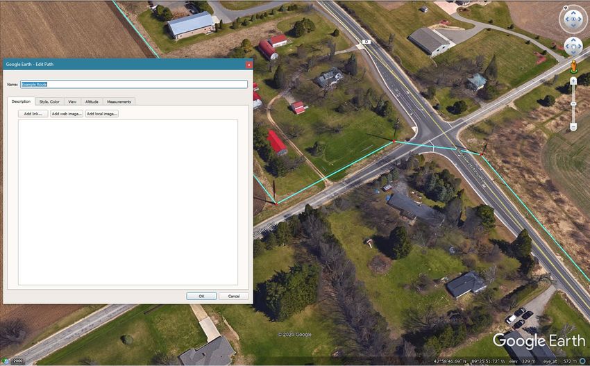
“Virtual” Site visits – using Street View functionality

Public approval / Visual impact studies for Environmental and Permitting Applications – and this really helps
landowners visualize the type and scale of infrastructure planned to be placed on their property, especially
when coupled with the 3D imagery that Google is rolling out (made using photogrammetry):

Copyright © Power Line Systems 2020                                                                 2
Google Earth is beneficial for use because it is free software (the standard version of the desktop program is
now Google Earth Pro - since July 2017), thus anyone can open and view the KML or KMZ files.

Coupling PLS-CADD with Google Earth allows the design outputs from Power Line Systems’ powerful and
industry leading structural, spatial, and electrical design features to be visualized by anyone, in an immersive
and realistic way on any device.

This technote discusses how to:

    •   Export the 3D model of the line to Google Earth
            o Hints and tips to get the best output experience are offered
    •   Create various design outputs and reports that can be exported directly to Google Earth.
    •   Import data (such as line routes) into PLS-CADD from a KML or KMZ file.

Copyright © Power Line Systems 2020                                                                   3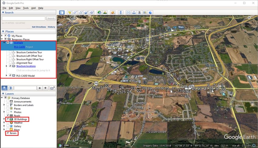
Export your project to a KML/KMZ

It has been possible to visualize your models in Google Earth since Version 8 of PLS-CADD. With the release of
version 16.50 these capabilities have been significantly improved and allow for more project information being
visible within Google Earth.

Create the KML/KMZ

To create a KML/KMZ file of your project, here are the step by step instructions and some tips for making best
use of this feature:

   •   Use Version 5 or newer of Google Earth: Everything demonstrated below uses Version 16.50 of PLS-
       CADD and Version 7.3.3.7721 of Google Earth. You can download Google Earth here.

   •   Open your project in PLS-CADD

       Note:

           o   Best results come from exporting the 3D view, as typically what is visible on the screen in the
               current active window will be exported, so if you export from the Plan view you will see the
               alignment & right-of-way lines and PI Symbols.

           o   Some features don’t transition well from PLS-CADD to the KML/KMZ file. For a pleasant aesthetic
               in the KML/KMZ it is a good reminder that typically what is visible in the active view will be
               exported. This includes Cable Attachment Points symbols, TIN surfaces and Markers.

Copyright © Power Line Systems 2020                                                                  4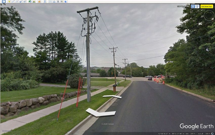
•   Ensure that the project coordinate system is defined - This is controlled under Terrain/ Coordinate
       System/ Define

           o   If you do not know what coordinate system to use, we advise that you contact the supplier of
               your survey data. Unfortunately XYZ point data does not have the coordinate system
               information built into it, so it is not possible for PLS-CADD to automatically detect and assign a
               coordinate system definition.

Copyright © Power Line Systems 2020                                                                    5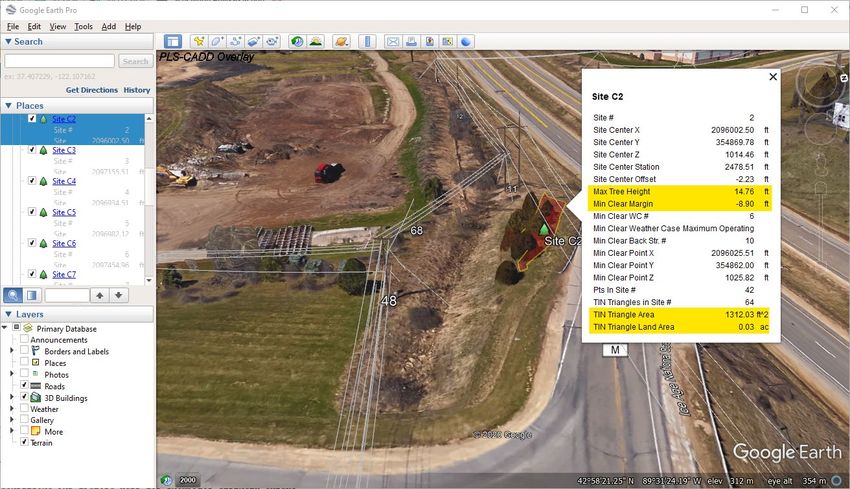
•   Export a KMZ - The Google Earth model is called a "KMZ" file and can be exported from PLS-CADD using
       the File/ Export/ KMZ (Google Earth) command.

   •   Name your KMZ - Enter a name for your KMZ and select a folder to save it in.

           o   If the Cable attachments are currently displayed, then you
               might receive a KML Aesthetics Warning indicating less
               than desirable aesthetics of the KML/KMZ file. To turn off
               the display of Cable Attachments you should deselect this
               option under the Drafting/ Show Cable Attachment Points
               menu.

Copyright © Power Line Systems 2020                                                               6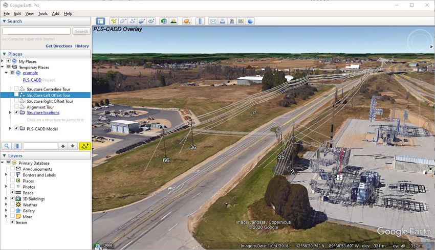
•   Select KMZ Export Options

           o   The Structure Location Settings have inputs for Range to view structure from and the Tilt. We
               suggest you leave these values at the default settings. These settings control how Google Earth
               views a structure when you jump to it from the Structure Locations list.

           o   You can choose the offset distance for the left and right structure tours (which you will see later
               in Google Earth). We recommend that you set this slightly larger than your maximum conductor
               offset (to simulate a helicopter flying as close to the line as possible).

           o   In some cases, the vertical datum used on your project may not be the same as what is used by
               Google Earth. The Elevation shift between PLS-CADD model and Google Earth input allows you to
               account for this. If your structures appear to be "floating" when you go to Google Earth, you can
               put a negative number in here to lower the entire line. Of course, the opposite is true if your line
               is buried. There is also an option to save the elevation shift with the project and apply it to
               reports exported to KML as well. If selected the elevation shift will be saved with the model and
               used for KML exports of reports and exports of the geometry.

Copyright © Power Line Systems 2020                                                                      7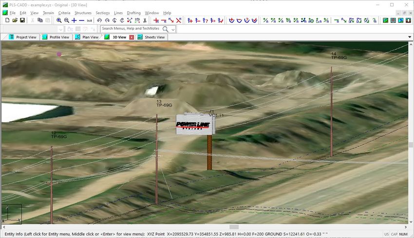
o   There is an option that allows you to define the Z coordinates in PLS-CADD are relative to mean
               sea level, not datum ellipsoid. If selected the elevations in the KMZ will be equal to the Z value in
               PLS-CADD plus and elevation shift entered above.

           o   There is an option to Draw lattice towers as Line, Wireframe or Render structures. Rendered
               structures can slow down Google Earth loading, but the performance has improved in recent
               versions (if the KMZ file is slow to load then you should investigate using Wireframe or Line type
               lattice structures).

           o   If selected the option Include insulator sheds in export will show the insulator sheds within the
               KMZ. It will also increase the size of the KMZ. If this option is not selected the insulators will be
               shown as a cylinder.

           o   The option to Draw cables with actual thickness (small cables will effectively be invisible) that
               when selected will use the actual cable width and cables may be difficult to see in Google Earth.

           o   There is an option to Color structures by usage when possible. This option will show the
               structures by % usage instead of the material. To activate this option, you will first need to run a
               structure usage report and then select this option when exporting the KMZ.

           o   You can opt to Include any raster attachments displayed in the plan view in the export you may
               have attached to your PLS-CADD project for use in Google Earth. Unfortunately, Google Earth
               does not handle detailed imagery as well as PLS-CADD does, so you may need to uncheck this
               option if navigating your model in Google Earth is slow.

           o   You can select to Include vector (DXF/SHP) attachments displayed in the 3d view in the export.

           o   You can also Automatically open in Google Earth after export and zoom directly to your line by
               leaving the last option checked.

               Click Here To Save The Example KMZ File Created For This Tech Note

       *Please Note: This is an example project, and while located in the same space as existing facilities it is
       not an exact representation of the actual facilities or their capabilities

Copyright © Power Line Systems 2020                                                                       8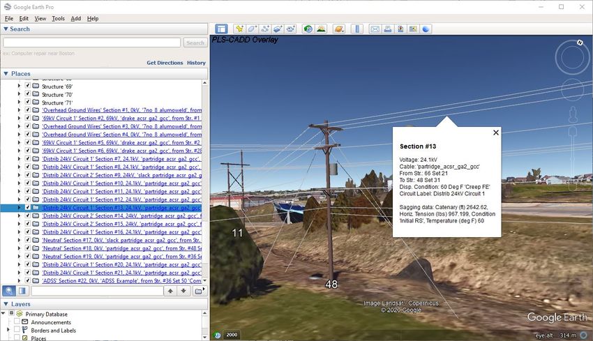
View the KML/KMZ
Once you click the OK button above (assuming you have left the Automatically open Google Earth after export
option selected), you will be taken directly to your line in Google Earth.
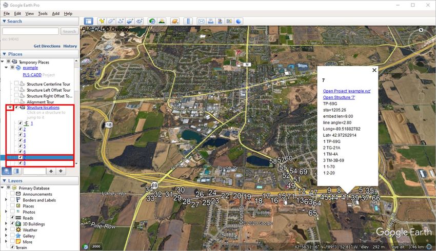
• The KMZ file will load by default in Temporary Places in the Places tree control.
• The KMZ file contains:
o Structure Tours (Centerline, Left Offset, Right Offset and an Alignment Tour).
o Structure Locations:
This shows a hyperlink to each structure position.
If Method 1 or stick structures are used, then PLS-CADD will add a small icon at the base
of the structure.
Copyright © Power Line Systems 2020 9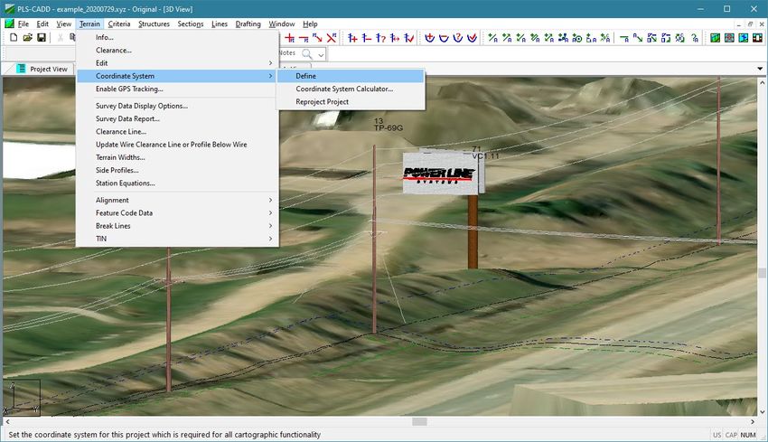
Double clicking on the structure number takes you directly to that structure in the
model.
o PLS-CADD Model, which comprises of:
Structures:
• A folder for each structure in the model with the graphical elements indicated,
which can be switched on or off independently.
Sections:
• A folder for each section of wire on the line, which can be switched on or off
independently.
A PLS-CADD overlay image to appear in the Top Left corner of the Google Earth screen.
• It is possible to Export Multiple Lines:
o You can load (File / Open) multiple KMZ files into Google Earth, so that you can see multiple
models at one time. Note that each project will now appear on the Temporary Places tree on
the left.
• Remember that, to see rendered structures in Google Earth, you must have used PLS-POLE and/or
TOWER to model your structures in PLS-CADD first. Otherwise, you will just see stick structures and
wires.
• If you don't have a project handy and want to immediately try this feature out, download this sample
KMZ file.
Click Here To Save The Example KMZ File Created For This Tech Note
*Please Note: This is an example project, and while located in the same space as existing facilities it is
not an exact representation of the actual facilities or their capabilities
Copyright © Power Line Systems 2020 10Google Earth Settings To ensure the best possible experience in Google Earth when viewing the line model and to leverage the ability to launch PLS-CADD, PLS-POLE and TOWER direct from the KMZ the following settings are recommended. These are primarily accessed under Tools/ Options. But also make sure that Terrain and 3D Buildings are checked in the Layers tree control in the lower left corner of Google Earth so that you are viewing the KMZ file in the full 3D receiving environment. Copyright © Power Line Systems 2020 11
3D View tab:

                                      The Elevation Exaggeration should be set to 1 to get an undistorted view of your structures
                                      and sags.

                                      To make Google Earth's terrain model a better match for your PLS-CADD model, select the
                                      option to Use high quality terrain.

                                      Also select the option to Use 3D Imagery this will use the newer photogrammetry generated
                                      3D surface. If you disable this setting you will use the legacy 3D buildings where available).

                                      You can select the Units of Measurement and the format for coordinates and a few other
                                      options.

                                      Touring tab:

                                      You can set the Camera Tilt Angle, Camera Range and Speed as well as other options.

                                      Camera Tilt Angle of 75 to 80-degree tilts appear to work best for most lines.

                                      Camera Range is a variable, depending on the size of your structures and their spacing.

                                      Also note that when a Tour is recorded you can prioritize a Smaller File or Higher Fidelity for
                                      the video captured. There are other options that you may want to investigate, such as the
                                      cache settings under the Cache tab. You can cache the imagery from a whole project for
                                      demonstrations later where you may not have Internet access rather than saving a video file of
                                      the Tour.

Copyright © Power Line Systems 2020                                                                                              12
General tab:
Important setting here to allow the hyperlinks to open the PLS-CADD .xyz model and the PLS-
POLE or TOWER files are:
• To enable the option to Show web results in external browser.
• To Allow access to local files and personal data.
• To Allow cross-origin requests for local content.
Copyright © Power Line Systems 2020 13Tour the line
• Double-click on one of the "tours" on the left-hand side of the screen under the line you want to tour.
You will be taken to the first structure on your line, hovering and ready to fly.
• To start the Tour, click the "Play Tour" button to start the tour (highlighted in the image below).
• You can make a movie/recording of your tour as well using the Tools/ Movie Maker capability built into
Google Earth Pro. However, note that the quality isn't anywhere near as good as it is "live" in Google
Earth.
Copyright © Power Line Systems 2020 14Structure and Section Attributes To get information or attributes of a structure or a wire section the following steps should be followed: Structure Attributes There are two simple methods to get structure attributes: Firstly, you can navigate to the lines KMZ file in the Places tree control and expand the Structure locations tree by clicking on the " " in front of that line. Now simply find the structure number in the expanded tree and click on it. Google Earth will then display the attributes of the structure. If you double click the structure number, Google Earth will navigate you to the structure. Copyright © Power Line Systems 2020 15
The second technique to get the structure attributes is to simply click on any part of the rendered structure (for
3D structures) or on the Structure Icon      at the structure base for Method 1 (stick) structures.

The details displayed for structures are:

    •   A hyperlink to open the .xyz project in PLS-CADD.
    •   A hyperlink to open the structure model in the appropriate structure program (PLS-POLE or TOWER).
    •   All the subsequent data/attributes are those selected in PLS-CADD under Drafting/ Structure and
        Section Labeling/ Sheet Profile View. Note that the Bill of Materials is one of those options. These are
        described in the PLS-CADD user manual in Section 5.4.5. In the example, the data selected is:
            o Structure Number
            o Structure Description
            o Station
            o Line Angle (if nonzero)
            o Longitude and Latitude
            o Embedment length
            o Material List – New items

This is a great way to share rich detail to other parties and field crews.

Section Attributes

Similarly, the Section Attributes can be displayed in two ways.

In the first technique, you can navigate to the lines KMZ file in the Places tree control and expand the PLS-CADD
Model tree by clicking on the " " in front of that line.

Copyright © Power Line Systems 2020                                                                    16
Now simply find the Section that you are interested in within the expanded tree and click on it. Google Earth will
then display the attributes of the section.
The second technique, much like the Structure Attributes, involves clicking directly on any part of the section in
the model which will display the attributes.
The details displayed for sections are:
• Voltage
• Cable file
• From structure
• To Structure
• Display Condition
• Circuit Label, and
• Sagging data
Copyright © Power Line Systems 2020 17PLS-CADD reports exportable to KML/KMZ
Many reports can now be exported to KML, this includes:
• P.I. Report
• Structure Coordinates Report
• Construction Staking Report
• Leg and Guy Extension Report
• Terrain Clearances by Span Report
• Thermal Rating Report
• Danger Tree Locator Report
• 2D EMF reports
• Line Summary Report:
o Structure List Report
o Structure Coordinates Report
o Structure Attachment Coordinates
A general rule is that any report which contains georeferenced coordinates can typically be exported to a KML
file. This ability can greatly enhance any text-based or tabular report to illustrate visually the design outputs. The
process to export the files is rather straight-forward.
When in the body of a report within PLS-CADD right click the mouse, then select KML export and choose the
report in question. It will then prompt you to save the file. After naming the file and selecting Save the program
will prompt you to see if you would like to view the report in the default system KML viewer which can be set to
Google Earth. This will then automatically launch the Google Earth Viewer and display the selected report.
This is demonstrated for Lines/ Reports/ Construction Staking Report below:
Copyright © Power Line Systems 2020 18Save the KMZ/KML to the desired location and then open the file in Google Earth (File / Open). Once loaded, you can click on any of the Placemarks/markers and see the attributes associated with the Construction Staking Report listed. You will see many data points but also a hyperlink to open the structure file in either PLS-POLE or TOWER. Notice below that not only are the geographical coordinates of the staking location given, but the pole class, pole length, base diameter, and structure weight are listed as well. Copyright © Power Line Systems 2020 19
Below is an example of the KML created by right clicking from the Lines/ Reports/ Thermal Rating Report.

Note that if markers are displayed in the 3D view in PLS-CADD, they will be exported with the PLS-CADD model
KML export as well (File/ Export/KMZ (Google Earth)).

This marker is the red line indicating the clearance available when the phase conductor is at 78°F in the image

Copyright © Power Line Systems 2020                                                                    20
Below is an example of the vegetation violations grouped into work sites and exported to a KMZ/KML file, as
discussed in the Wildfire Risk Assessment Using PLS-CADD technote and the PLS-CADD Vegetation Work Sites
video, using the Lines/ Reports/ Danger Tree Locator functionality in PLS-CADD to detect Grow-In and Falling
Tree clearance violations. This typically requires vegetation survey points to have been collected (typically by
LIDAR survey).

By using these Google Earth export functions in PLS-CADD, information from your PLS-CADD model can be
shared with others for informational, construction and vegetation management purposes quickly and easily.

Copyright © Power Line Systems 2020                                                                  21
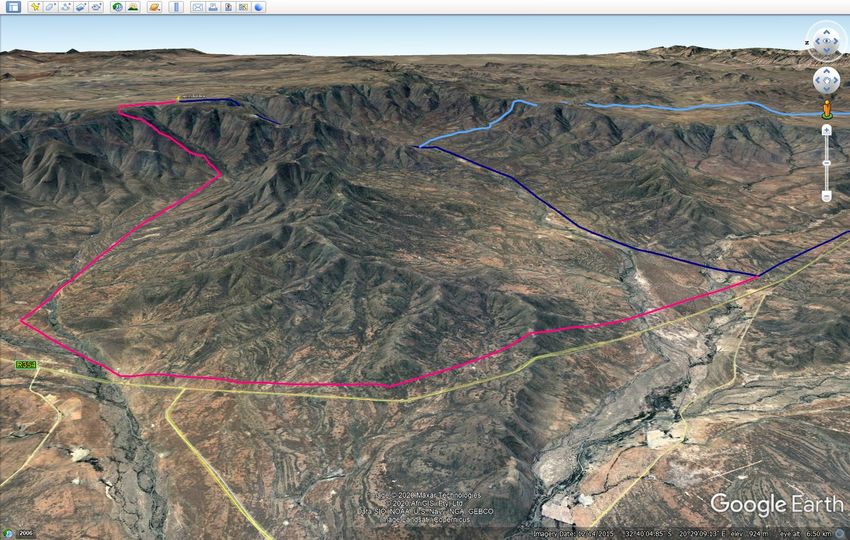
Import data from KML/KMZ

Importing terrain data from a KML/KMZ file is a straightforward process and is briefly described in Appendix D.9
of the PLS-CADD Manual. PLS-CADD will create a survey point at each Placemark and at each “point” or “bend”
along any Path (LineString) elements in the file. The points along a path can be visualized as the red dots when
you edit a Path by right clicking on it in the Places tree and select "Properties".

It is good practice to keep your KML/KMZ files containing only the information you wish to bring into PLS-CADD.

Once you have started creating your project you should ideally have:

   •   Loaded a FEA file (Terrain/ Feature Code Data/ Load FEA)
   •   Defined the Project Coordinate System (Terrain/ Coordinate System/ Define)

At this point you are able to accurately import the KML/KMZ file. To do so, use the Terrain/ Edit/ Merge Points
from External File/ Merge Points from KML/KMZ files… command.
       Click Here To Save The Example KML Line Path Created For This Tech Note

Copyright © Power Line Systems 2020                                                                  22
After finding and selecting the KML/KMZ file you wish to use, the Select Feature Code for New Points dialog box will display. In this dialog you can select the feature code that you would like for the imported points from the picklist. You can choose whether to use the point filter upon import of the points and /or create an alignment based on each LineString entity in the file. The third tick box (selected in the figure) will place the contents of any name and/or description entities in the Plan Comments for the xyz points created. The bottom option will use the elevation from the TIN as the Z value for points created from the KMZ file. Copyright © Power Line Systems 2020 23
Once the points have been created, a range of other PLS-CADD features will very quickly provide you with a
usable alignment and terrain data for making design determinations.

For example:

   •   Terrain/ Alignment/ Automatic Alignment
   •   Terrain/ Edit/ Merge Points from External File/ Merge Points from Internet (See video here Download
       XYZ Point Data From Internet)
   •   Terrain/ TIN/ Create TIN and Terrain/ TIN/ Create Interpolated Points
   •   Attaching aerial imagery from online sources (See video for PLS-CADD Web Mapping Services)

Copyright © Power Line Systems 2020                                                             24
You can also read