Effect of Repetitive Collar Replacement on the Residual Strength and Fatigue Life of Retained Hi-Lok Fastener Pins - MDPI
←
→
Page content transcription
If your browser does not render page correctly, please read the page content below
metals
Article
Effect of Repetitive Collar Replacement on the
Residual Strength and Fatigue Life of Retained
Hi-Lok Fastener Pins
David F. Hardy † and David L. DuQuesnay *
 Department of Mechanical and Aerospace Engineering, Royal military College of Canada, PO Box 17000 Station
 Forces, Kingston, ON K7K 7B4, Canada; David.Hardy@forces.gc.ca
 * Correspondence: duquesnay-d@rmc.ca; Tel.: +613-541-6000 (ext. 6483)
 † Currently: DT4 Structural Engineer, Aerospace Telecommunications and Engineering Support Squadron,
   K0K 3W0 Astra, ON, Canada.

 Received: 13 March 2019; Accepted: 9 April 2019; Published: 16 April 2019

 Abstract: Hi-Lok fasteners were subjected to multiple collar replacements, and were tested under static
 loading and constant-amplitude fatigue loading, to determine the effect of repetitive collar replacement
 on the residual strength and fatigue life of a retained Hi-Lok-type fastener pin. Hi-Lok-type fasteners
 are typically used in aircraft structural joints, and are loaded mainly in shear. Tests were conducted for
 clamping force, static shear strength, static tensile strength, and shear fatigue life for collars subjected
 to five collar replacements. The static shear results showed no decrease in the ultimate shear strength
 of the fastener pin as a function of collar replacement. Static tensile results showed no decrease
 in the ultimate tensile strength of the fastener as a function of collar replacement, with failure of
 the aluminum collar remaining the critical failure mode. Similarly, shear fatigue results showed no
 decrease in the shear fatigue life of the fastened joint as a result of collar replacement, with fracture of
 the aluminum substrate remaining the critical failure mode. For static shear, static tension, and shear
 fatigue tests, estimated clamping force was highly consistent between specimens and no decrease in
 clamping force was observed as a function of collar replacement.

 Keywords: aircraft; fatigue; fastener; reuse

1. Introduction
     Hi-Lok-type [1] fasteners are used extensively in the aerospace industry, and consist of a threaded
fastener pin and collar. The threaded collar includes a wrenching element that shears-off at a fixed torque,
enabling rapid installation while ensuring a consistent pre-load for each fastener. The manufacturer’s
installation instructions recommend retention and reuse of undamaged Hi-Lok fastener pins following
collar removal [2]; however, current Royal Canadian Air Force (RCAF) maintenance procedures [3] call
for the replacement of an installed aircraft Hi-Lok fastener pin each time the collar is removed.
     Despite this current practice, it may be preferable from an aircraft maintenance standpoint
to remove and replace the collars without replacing the installed fastener pins in some instances.
Specifically, retention of the installed pins may be preferable when accessing fastener holes for
Non-Destructive Inspection (NDI) of aircraft structure using techniques such as Eddy Current Surface
Scan (ECSS). NDI necessitating scheduled collar removal is often carried out in structural areas where
fatigue cracking is a concern. By far, the most commonly used technique to detect fatigue damage in
and around aircraft fasteners involves eddy current (EC) inspection. Fhar and Wallace [4] provide a
comprehensive discussion of various NDI techniques used to inspect fastener holes in aircraft structures.
The most common and reliable method is the bolt hole eddy current (BHEC) that requires the removal
of the fastener itself to permit a probe into the faster hole for inspection. However, the removal and

Metals 2019, 9, 445; doi:10.3390/met9040445                                      www.mdpi.com/journal/metals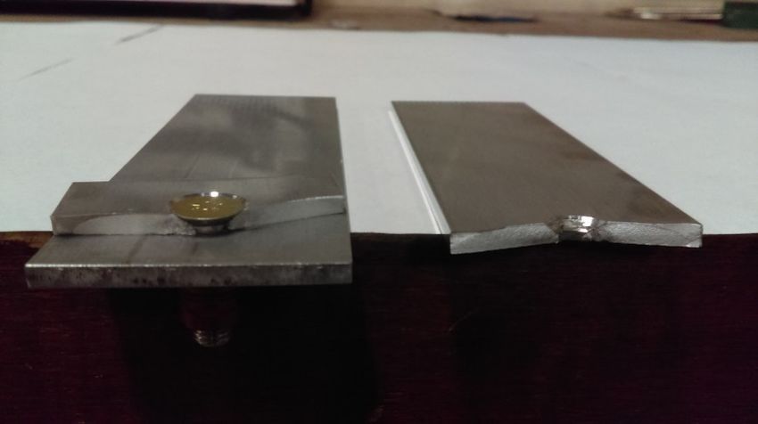
fatigue damage in and around aircraft fasteners involves eddy current (EC) inspection. Fhar and
Wallace [4] provide a comprehensive discussion of various NDI techniques used to inspect fastener
holes in aircraft structures. The most common and reliable method is the bolt hole eddy current
(BHEC)
Metals 2019,that
9, 445requires the removal of the fastener itself to permit a probe into the faster hole 2 offor
16
inspection. However, the removal and re-installation of interference fit fastener pins causes
mechanical damage to the fastener hole due to strain and physical abrasion. It is clear that repetitive
re-installation of interference
removal and installation fit fastener pins
of interference causes mechanical
fit fastener pins throughout damage thetolife
theoffastener hole due
the aircraft will
to strain and physical abrasion. It is clear that repetitive removal
produce far more mechanical damage than if the initial fastener pin were retained. Thus, ironically, and installation of interference
fit
thefastener
periodicpins throughout
removal the life of the
and reinstallation ofaircraft
interferencewill produce far more
fit fastener pins formechanical damage than
NDI of fatigue-prone
if
areas risks exacerbating the existing fatigue concerns at these locations by generating of
the initial fastener pin were retained. Thus, ironically, the periodic removal and reinstallation or
interference fit fastener pins for NDI of fatigue-prone areas
aggravating existing crack initiations. Although not as powerful as BHEC at detecting cracks,risks exacerbating the existing fatigue
concerns
especiallyatcracksthese within
locations theby generating
bore of fasteror aggravating
hole, ECSS canexisting crack to
still be used initiations. Although
detect surface cracks.notTheas
powerful as BHEC at detecting cracks, especially cracks within the bore
removal of the fastener collar enables detection of cracks at the edge of the fastener hole, rather than of faster hole, ECSS can still be
used to detect surface
only detecting cracks cracks.
that extendThe removal
past the of edgetheoffastener collar enables
the installed collar. Itdetection
has beenofshowncracksthatat the edge
fatigue
of the fastener hole, rather than only detecting cracks that extend
crack growth in aircraft structure under a variety of loading conditions follows an exponential past the edge of the installed collar.
It has been
growth rateshownwith thatusagefatigue
(cycles crack growth in
or flights) withaircraft structureof
the majority under a variety
fatigue of loading
lifetime spent with conditions
cracks
follows an exponential growth rate with usage (cycles or flights) with
relatively small, approximately 5 mm or less [5]. Because of the exponential nature of crack growth, the majority of fatigue lifetime
spent with cracks
the ability to detect relatively
fatiguesmall,
cracks approximately
while they remain 5 mm orrelatively
less [5]. Because of the exponential
short significantly increases nature
the
of crack growth, the ability to detect fatigue cracks while
allowable time between inspections, considerably reducing manpower requirements and they remain relatively short significantly
increases
maintenance the allowable
downtimetime between
for the inspections,
affected considerably reducing manpower requirements and
aircraft fleet.
maintenance downtime for the affected aircraft fleet.
The replacement of fastener collars for NDI without the removal of the interference fit fastener
pins mayreplacement
The therefore help of fastener
to maximizecollars for
theNDI without
fatigue thethe
life of removal of the
aircraft interference
structure beingfitinspected.
fastener pins An
may
example of a structural area where repetitive collar replacement was considered for example
therefore help to maximize the fatigue life of the aircraft structure being inspected. An use in the of
aRCAF
structural area where repetitive collar replacement was considered
is shown in Figure 1 for Critical Point 16 on the CP140 Aurora [6]. Selected hardware, test for use in the RCAF is shown in
Figure 1
specimens, for Critical
and applied Point loads
16 on the for CP140 Aurorawere
this project [6]. Selected
based on hardware, test specimens,
the fasteners and structureand applied
at this
loads for this project were based on the fasteners and structure
location. Although the fatigue behavior of fasteners and joints in aircraft structure has been at this location. Although the studied
fatigue
behavior
extensively of fasteners
[5,7], onlyand joints
a few in aircraft
studies havestructure
been done hason beenthestudied
effect ofextensively [5,7], only a few
repeated re-installation of
studies have been done on the effect of repeated re-installation of fasteners.
fasteners. Li and Su [8] studied the effect of repeatedly tightening and loosening the nut on titanium Li and Su [8] studied the
effect of repeatedly
fasteners in a carbon tightening and loosening
fibre composite the nutThey
structure. on titanium
found fasteners
that the in a carbon load
clamping fibre composite
decreased
structure. They found that the clamping load decreased rapidly
rapidly with repeated loosening-tightening cycles with a drop in clamp load between 66–76% with repeated loosening-tightening
cycles
withinwithfive arepetitions
drop in clamp and load
down between
to about 66–76%
45% after within15 five repetitions
repetitions. and down
Clamping to is
load about 45%toafter
critical the
15 repetitions. Clamping load is critical to the fatigue performance of
fatigue performance of typical fastened aircraft structural joint, with a decrease in clamping load typical fastened aircraft structural
joint, with
leading a decrease
to early fatigue in failure
clamping [7].load leading to early fatigue failure [7].
Figure 1. CP140 Critical Point 16 inboard engine nacelle skate angle.
Despite the current RCAF practice of replacing fastener pins and collars at each inspection, it is
evident that there is a benefit, and it would be convenient, to retain the faster pins in some situations
while removing only the collar to allow clear access to the fastener hole for inspection. The effect of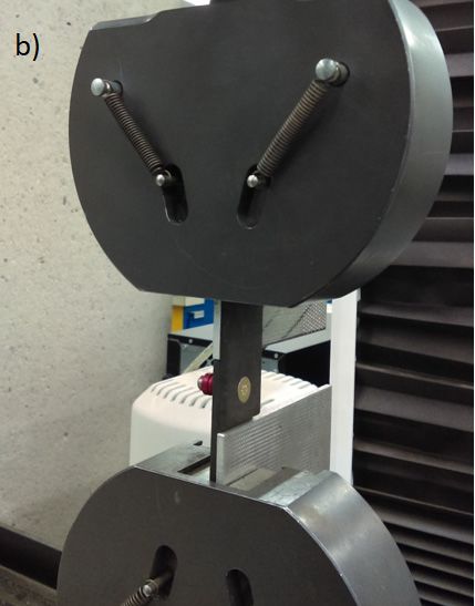
Metals 2019, 9, 445                                                                                    3 of 16

repeated replacement of the collar on Hi-Lok pins on the subsequent strength and life of the fastener,
and on the clamping load has not yet been reported. The aim of this research was to determine the
effect of repetitive collar replacement on the residual clamping force, static strength, and fatigue life
of retained Hi-Lok-type fastener pins. Fasteners were tested separately in both tension and shear to
determine their behaviour under each primary loading condition. The results of this study will provide
some evidence to support the practice of repeated collar replacements on retained Hi-Lok fasteners
in aircraft structure where pin removal would be difficult, as is the case for Critical Point 16 on the
CP140 Aurora [6].

1.1. Equivalent Interference Fits
      Most aerospace applications of Hi-Lok-type fasteners use interference fits between the pins and
fastener holes to generate localized compressive stresses that reduce crack growth rates, improving
the fatigue life of the component. Critical Point 16 on the CP140 Aurora is taken as a representative
example of a fatigue-prone aircraft structure where Hi-Lok-type fasteners are employed. This location
calls for 0.245” to 0.248” (6.22 mm to 6.30 mm) diameter fastener holes [9,10] in the 7075-T6 aluminum
structure to accommodate 0.249” (6.32 mm) diameter steel fastener pins, resulting in an interference of
0.001” to 0.004” (0.025 mm to 0.100 mm) between the pins and the substrate.
      In order to generate an equivalent amount of physical interference and resultant mechanical
damage in the test specimens for this project, 0.245” (6.22 mm) diameter reamed fastener holes were
used for all aluminum shear test fixtures. Because strength and fatigue requirements resulted in
some of the test specimens, such as the tensile test jigs, being manufactured from high-strength steel,
the physical interference of fastener holes in the steel test fixtures is reduced to ensure a similar level of
mechanical damage to the fastener pin during installation. When determining the appropriate level of
interference fit, it is assumed that the mechanical damage to the pin during installation is proportional
to its radial strain.
      For the aluminum plates in the shear test fixtures, total deformation at the fastener hole, ∆Dtotal ,
is equal to the difference between the diameters of the fastener pin, Dpin , and fastener hole, Dhole :

                                           ∆Dtotal = Dpin − Dhole .                                       (1)

      Part of this deformation is caused by negative strain (radial compression) of the pin, while the
remainder is accommodated by positive strain (radial expansion) of the fastener hole.
      The deformation of the pin can be expressed in terms of the deformation of the fastener hole,
knowing that the relative strains of these components will be directly proportional to the relative
stiffness of the pin and plate materials:
                                             εpin     Eplate
                                                   =         ,                                    (2a)
                                             εhole    Epin
                                                           ∆Dpin

                                             Eplate        Dpin
                                                      =  ∆D           ,                                (2b)
                                              Epin              hole
                                                           Dhole

                                                  Dhole ∆Dpin
                                              =                        ,                                 (2c)
                                                     Dpin ∆Dhole
                                                     Dpin ∆Dhole Eplate
                                                                                  !
                                       ∆Dpin =                                        ,                  (2d)
                                                        Dhole              Epin
where |εpin | is the absolute radial strain of the pin (by convention, compressive strain will have a
negative value),
    εhole is the radial strain of the fastener hole,
    Epin is the elastic modulus of the HL51-8-6 fastener pin material, 2.9 × 10⁴ ksi (199 GPa) [11],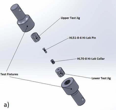
Metals 2019, 9, 445                                                                                   4 of 16

    Eplate is the elastic modulus of the 7075-T6 plate material, 1.03 × 10⁴ ksi (70 GPa) [11],
    |∆Dpin | is the absolute radial deformation of the pin (compressive deformation will have a negative
value), and
    ∆Dhole is the radial deformation of the fastener hole.
    Substitute Equation (1) into Equation (2) and solve for the deformation of the pin:

                                                                         A

                                                 ∆Dpin = ∆Dtotal             ,                           (3)
                                                                        1+A
               Dpin Eplate
where A = D E .
            hole pin
    Calculating deformation of the fastener pin in the aluminum plates:

                             ∆Dtotal = Dpin − Dhole = (0.249) − (0.245) = 0.004” (0.100 mm),           (4a)

                                           Dpin Eplate   (0.249) 1.03 × 10⁴
                                      A=              =                         = 0.36,                (4b)
                                           Dhole Epin    (0.245)(2.90 × 10⁴ )
                                            A                         0.36

                      ∆Dpin = ∆Dtotal               = 4.00 × 10−3              = 0.001” (0.025 mm).     (4c)
                                           1+A                      1 + 0.36
     Because aluminum has a much lower elastic modulus than steel, aluminum test jigs will have a
greater amount of deformation relative to the steel fastener pin than steel test jigs, assuming equal
dimensions. In order to ensure the same level of mechanical damage for the fastener pins in the steel
axial test jig, radial strain (and therefore radial deformation) of the fastener pin is held constant.
     To find the interference fit that will generate the same radial deformation of the pin in a
high-strength steel fixture, Equation (2) is solved for deformation of the fastener hole:

                                                         Dpin ∆Dhole Eplate
                                                                                   !
                                               ∆Dpin =                                 ,               (5a)
                                                            Dhole         Epin

                                                         Dhole ∆Dpin      Epin
                                                                                   !
                                              ∆Dhole =                                 .               (5b)
                                                            Dpin          Eplate
      Rearranging Equation (1), the initial diameter of the fastener hole is equal to:

                                                  Dhole = ∆Dpin −∆Dtotal .                               (6)

      Because the initial fastener hole diameter and radial deformation of the fastener hole are
interdependent, the equations above are iterated for increasing values of Dhole until a solution
converges. For a defined absolute pin deformation of 0.0011” (0.027 mm):
      Dhole = 0.247” (6.30 mm).
      A 0.247” diameter (6.30 mm) reamed fastener hole was therefore used for the high-strength steel
test fixtures.

1.2. Measurement of Clamping Force
      Clamping force or “preload” is a major consideration for fastened joints. The application of a
tensile preload to a fastener pin improves the fatigue life of the pin and the joint by decreasing the
effective stress amplitude. Estimation of the clamping force in a fastened joint is therefore an important
metric when assessing the impact of repetitive collar replacement on a retained fastener pin.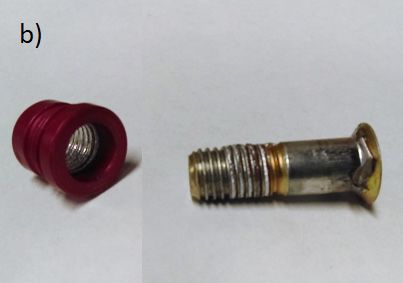
Metals 2019, 9, 445                                                                                   5 of 16

     The tightening torque, Ton , of a fastener can be related to the induced clamping force, F, by the
following expression described by Eccles [12,13]:

                                                 F µt d2
                                                  "               #
                                                          p
                                      Ton      =         + + De µn ,                                     (7)
                                                 2 cos β π

where µt is the coefficient of friction for the thread;
    d2 is the basic pitch diameter of the thread;
    β is the half-included angle of the threads (30◦ for UNF threads);
    p is the pitch of the threads;
    µe is the coefficient of friction for the nut face; and
    De = 12 (di + do ) is the effective bearing diameter of the nut,
    where di and do are the inner and outer bearing diameters of the nut, respectively.
    The loosening torque, Toff , can similarly be related to the clamping force by the expression:

                                                 F µt d2
                                                  "                 #
                                                          p
                                      To f f   =         − + De µ n                                      (8)
                                                 2 cos β π

    From these equations, the difference between the tightening and loosening torques can be
simplified into the following expression:
                                                                p
                                               Ton − To f f   =F    .                                    (9)
                                                                 π

    Rearranging Equation (8), the clamping force in the joint can be simply related to the difference
between the tightening and loosening torques, as follows:
                                                    π
                                               F=      Ton − To f f .                                  (10)
                                                    p

     The uncertainty of clamping force estimates calculated using this method varies depending
on the method of torque application, but is generally found to fall within ±17% using a precision
torque wrench [7].
     While Eccles [12,13] recommends the use of an on–off–on measurement process to record tightening
and loosening torques for the fastener, this process is not practical for Hi-Lok-type collars. Because the
wrenching element of the collar torques-off at a pre-determined torque during installation, subsequent
tightening of the collar is not easily achieved and is difficult to measure accurately. Moreover, loosening
of the collar can only be achieved and accurately measured by damaging means, using specialized
Hi-Lok removal tools. For the purposes of this experiment, tightening torque, Ton , is therefore assumed
to be equal to the peak torque achieved during installation of the collar. Loosening torque, Toff , is taken
as the peak torque achieved during removal of the collar.

2. Materials and Methods
      The fasteners used in this project are the Hi-Lok HL51-8-6 (HL19 equivalent) 0.25” (6.35 mm)
diameter 100◦ flush shear head cadmium-plated alloy steel fastener pins with HL70-8 aluminum
collars. These are the countersunk fastener type used on the CP140 Aurora at Critical Point 16, and are
used extensively on CP140 and CC130 aircraft. Moreover, these alloy steel flush shear head fasteners
are broadly representative of similar Hi-Lok-type fasteners used across many other RCAF aircraft
fleets. This type of fastener is designed and intended to take shear loading. The specified mechanical
properties of the fasteners and collars are given in Tables 1 and 2, respectively.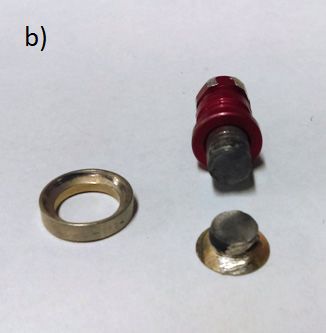
Metals 2019, 9, 445                                                                                           6 of 16

                           Table 1. Mechanical properties of HL51-8-6 fastener pin [11].

                      Property                     Value (as Specified)               Value (SI Equivalent)
                Shaft diameter, D                     0.249 ± 0.010”                    6.32 ± 0.025 mm
                  Grip Length, L                      0.375 ± 0.005”                    9.52 ± 0.127 mm
                      Thread                        0.250-28 UNJF-3A                            -
                     Material                           Alloy Steel                             -
                Surface Treatment                       Cadmium
                                                                                            199 GPa
                 Elastic Modulus                        29,000 ksi
        Ultimate Single Shear Strength, Psu              ≥4650 lbf                          ≥20.7 kN
          Ultimate Tensile Strength, Ptu                 ≥3700 lbf                          ≥16.5 kN
            Ultimate Shear Stress, Fsu                    ≥95 ksi                          ≥654 MPa
            Ultimate Tensile Stress, Ftu               160–180 ksi                       1100–1240 MPa

                                 Table 2. General properties of HL70-8 collar [14].

                      Property                     Value (as Specified)               Value (SI Equivalent)
               Outer Diameter, D                       0.249 ± 0.010”                   6.32 ± 0.025 mm
              Retained Length, L (*)                   0.375 ± 0.005”                   9.52 ± 0.127 mm
                     Thread                          0.250-28 UNJF-3B                            -
                    Material                        2024-T6 Aluminum                             -
          Ultimate Tensile Strength, Ptu                  ≥3000 lbf                          13.3 kN
             Torque (on installation)                   60–80 lbf - in                   6.78–9.04 Nm
                                    * Length after torque-off of wrenching element.

     Fasteners were installed and removed using a DTL-100i Digital Torque Wrench and compatible
3/8” socket, an Allen key, and SAVI-32, -34, and -36 Hi-Lok removal tools.

2.1. Procedures
     Unless otherwise shown, ten repetitions of each specimen type were tested to generate statistically
significant results. All shear test specimens were made with the same dimensions, consisting of two
strips of material measuring 1.50” × 4.50” × 0.125” (38.1 mm × 114 mm × 3.17 mm) with a single
fastener installed in the overlap. An edge distance, e = 0.50” (12.7 mm) was used for all fastener
holes. This edge distance is reflective of typical aircraft structure and allows direct comparison with
manufacturers’ material strength values, which are typically quoted for edge distances of 2D or greater.

2.2. Baseline Static Shear
    Fasteners were installed in accordance with [3] into single-fastener lap joints made from AISI
Type O1 steel plates and tested monotonically to failure. The test fixture is illustrated in Figure 2.
The ultimate shear strength and failure mode were recorded for each specimen.

2.3. Static Shear with Collar Replacement
     Following completion of the baseline tests, static shear tests were conducted on fasteners subjected
to multiple collar replacements. Fasteners were installed in accordance with [3] into single-fastener
interference fit lap joints made from 7075-T6 aluminum sheet. Collars were removed and re-installed in
accordance with [3] for a total of five collar replacements. The loosening and tightening torques for all
collars were measured using a digital torque wrench to enable calculation of the clamping force of each
collar in accordance with [11]. Following the fifth and final collar replacement, the fastener pins were
removed from the aluminum plate specimens and installed with a clearance fit in accordance with [3]
into heat treated AISI Type O1 steel sheet (Figure 2), which provided the high strength required for
shear testing of the fastener pins. In an aircraft inspection scenario, the possibility of damaging the
substrate material would be a major concern, but, in our case, damage to the fastener pin was of interest.
The pins were carefully pressed out in a single continuous motion and then visually inspected under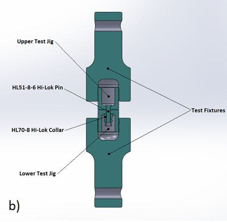
consisting of two strips of material measuring 1.50” × 4.50” × 0.125” (38.1 mm × 114 mm × 3.17 mm)
with a single fastener installed in the overlap. An edge distance, e = 0.50” (12.7 mm) was used for all
fastener holes. This edge distance is reflective of typical aircraft structure and allows direct
comparison with manufacturers’ material strength values, which are typically quoted for edge
distances of 2D or greater.
Metals 2019, 9, 445                                                                                                 7 of 16

2.2 Baseline Static Shear
light Fasteners
      microscope   (up installed
                 were  to 20×). No
                                 in discernable
                                    accordance damage
                                                  with [3]was
                                                          intovisible on any fastener
                                                               single-fastener        shank.
                                                                               lap joints    Thefrom
                                                                                          made    fasteners
                                                                                                       AISI
were
Type O1 steel plates and tested monotonically to failure. The test fixture is illustrated in Figurefor
      then tested  monotonically  to failure to determine the ultimate shear strength and failure mode   2.
each  specimen.
The ultimate shear strength and failure mode were recorded for each specimen.

 Metals 2019, 9, x FOR PEER REVIEW                                                                                 7 of 16

 of the clamping force of each collar in accordance with [11]. Following the fifth and final collar
 replacement, the fastener pins were removed from the aluminum plate specimens and installed
 with a clearance fit in accordance with [3] into heat treated AISI Type O1 steel sheet (Figure 2),
 which provided the high strength required for shear testing of the fastener pins. In an aircraft
 inspection scenario, the possibility of damaging the substrate material would be a major concern,
 but, in our case, damage to the fastener pin was of interest. The pins were carefully pressed out in a
 single continuous motion and then visually inspected under light microscope (up to 20×). No
 discernable damage was visible on any fastener shank. The fasteners were then tested
 monotonically     to shear
     Figure 2. Static  failuretesttoassembly
                                      determine    the ultimate
                                              (a) aluminum  joint shear  strength
                                                                  for repeated     and
                                                                               collar    failure mode
                                                                                      installation and (b)for
                                                                                                           steeleach
     Figuretest
 specimen.
     shear   2. Static
                fixtureshear  test in
                        installed   assembly  (a) aluminum joint for repeated collar installation and (b) steel
                                      test machine.
      shear test fixture installed in test machine.
2.4. Static Tension
 2.4 Static  Tension
2.3 Static
      Tests Shear with   Collar Replacement the baseline ultimate tensile strength of the fasteners with no
       Testswere
              wereconducted
                     conductedtotodetermine
                                       determine the baseline ultimate tensile strength of the fasteners with
collar  replacement.
      Following          The
                    completionfasteners
                                   of
 no collar replacement. The fasteners   thewere  installed
                                             baseline
                                                were        in accordance
                                                        tests, static
                                                       installed        shearwith
                                                                  in accordance     [3]were
                                                                               testswithinto
                                                                                           [3]an  SAE4340
                                                                                              conducted
                                                                                                into         steel
                                                                                                            on
                                                                                                     an SAE4340     tensile
                                                                                                                fasteners
                                                                                                                     steel
test fixture
subjected     and  tested
 tensile testtofixture
                 multiple  monotonically
                        and collar            to failure.
                                      replacements. to
                             tested monotonically         This  test
                                                        Fasteners    fixture
                                                                     weretest
                                                          failure. This      is illustrated
                                                                            installed         in Figure
                                                                              fixture isinillustrated
                                                                                            accordance   3. The  ultimate
                                                                                                           with [3]
                                                                                                       in Figure       into
                                                                                                                   3. The
tensile
 ultimatestrength
single-fastener     and  failure
            tensileinterference
                     strength    mode
                               and     lapwas
                                  fitfailure    recorded
                                           joints
                                              modemade     for each
                                                     wasfrom         specimen.
                                                                7075-T6
                                                          recorded         aluminum
                                                                      for each          sheet. Collars were removed
                                                                                specimen.
and re-installed in accordance with [3] for a total of five collar replacements. The loosening and
tightening torques for all collars were measured using a digital torque wrench to enable calculation

          Figure 3. Static tension test assembly (a) exploded view and (b) cross section of the assembly.
          Figure 3. Static tension test assembly (a) exploded view and (b) cross section of the assembly.

 2.5 Static Tension with Collar Replacement
      Following completion of the baseline tests, static tensile tests were conducted on fasteners
 subjected to multiple collar replacements. Collars were removed and re-installed in accordance
 with [3] for a total of five collar replacements. The loosening and tightening torques for all collars
 are measured using a digital torque wrench to enable calculation of the clamping force of each
 collar in accordance with [11]. Following the fifth and final collar replacement, the Hi-Lok fasteners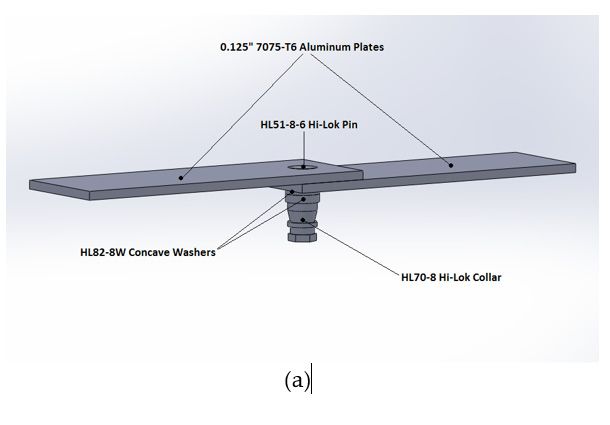
Metals 2019, 9, 445                                                                                                  8 of 16

   2.5. Static Tension with Collar Replacement
         Following completion of the baseline tests, static tensile tests were conducted on fasteners subjected
   to multiple collar replacements. Collars were removed and re-installed in accordance with [3] for a total
   of five collar replacements. The loosening and tightening torques for all collars are measured using a
   digital torque wrench to enable calculation of the clamping force of each collar in accordance with [11].
   Following the fifth and final collar replacement, the Hi-Lok fasteners were tested monotonically to
   failure to determine the ultimate tensile strengths and critical failure modes for each specimen.

   2.6. Baseline Shear Fatigue
          Tests were conducted to calibrate load levels and determine the baseline fatigue life for the
    specimens with no collar replacement. The fasteners were installed in accordance with [3] into
    single-fastener lap joints made from 7075-T6 aluminum sheet. The assembled specimens were installed
    into a servo-hydraulic test system and subjected to constant-amplitude loading with a load ratio,
    R=
Metals   0 and
       2019,       a maximum
             9, x FOR PEER REVIEWshear fatigue load of 900 lbf (4.0 kN) based on the allowable shear 8load
                                                                                                       of 16 for
    these fasteners4 , calibrated to obtain an average fatigue life of around 500,000 cycles. Shear fatigue
for test
     these   fastenersused
         specimens
                        4, calibrated to obtain an average fatigue life of around 500,000 cycles. Shear
                             the configuration shown in Figure 2a. Installed and failed specimens are shown
fatigue   test specimens
    in Figure    4.          used the configuration shown in Figure 2a. Installed and failed specimens
are shown in Figure 4.

                    (a)                                                         (b)

                 Figure 4. Shear fatigue test specimen (a) loaded in test frame and (b) failed in fatigue.
              Figure 4. Shear fatigue test specimen (a) loaded in test frame and (b) failed in fatigue.
   2.7. Shear Fatigue with Collar Replacement
2.7 ShearFollowing
            Fatigue with   Collar Replacement
                       completion     of the baseline tests, shear fatigue tests were conducted on specimens
    subjected    to multiple    collar
       Following completion of the       replacements.
                                            baseline tests,Fasteners   weretests
                                                            shear fatigue        installed
                                                                                       were in  accordance
                                                                                             conducted         with [3] into
                                                                                                          on specimens
subjected to multiple collar replacements. Fasteners were installed in accordance withtest
    single-fastener   lap  joints made    from 2 overlapping   strips  of  7075-T6     aluminum    sheet. The     [3]fixture
                                                                                                                       into is
    illustrated inlap
single-fastener     Figure    4a.made
                         joints   The assembled     specimens were
                                          from 2 overlapping      stripsinstalled
                                                                           of 7075-T6 into aluminum
                                                                                           a servo-hydraulic     test system
                                                                                                         sheet. The     test
    and   subjected   to  a constant-amplitude      shear  fatigue  load,    as  calibrated   during
fixture is illustrated in Figure 4a. The assembled specimens were installed into a servo-hydraulic     the baseline    fatigue
testtests.
      systemTheand
                 Hi-Lok    collars to
                      subjected    were    removed and re-installed
                                      a constant-amplitude       shear in    accordance
                                                                          fatigue     load, with  [3] after aduring
                                                                                            as calibrated     fixed number
                                                                                                                         the
    of  load  cycles.  The   baseline   fatigue  tests gave  a mean    fatigue     life of approximately
baseline fatigue tests. The Hi-Lok collars were removed and re-installed in accordance with [3] after        560,000     cycles
a fixed number of load cycles. The baseline fatigue tests gave a mean fatigue life of approximately of
    with   a standard   deviation    of 0.159  on logarithmic   fatigue    life.  Assuming     log-normal    distribution
560,000 cycles with a standard deviation of 0.159 on logarithmic fatigue life. Assuming log-normal
distribution of fatigue life values, the 98% confidence level occurs at roughly 2 standard deviations
below the mean life, or approximately 250,000 cycles. This was considered to be the “service life” of
the joint. Hence, the experimental shear fatigue test specimens were subjected to five collar changes
at intervals of 45,000 cycles, based on the lower 98 % confidence interval of the baseline fatigue life.
Metals 2019, 9, 445 9 of 16
fatigue life values, the 98% confidence level occurs at roughly 2 standard deviations below the mean
life, or approximately 250,000 cycles. This was considered to be the “service life” of the joint. Hence,
the experimental shear fatigue test specimens were subjected to five collar changes at intervals of
45,000 cycles, based on the lower 98 % confidence interval of the baseline fatigue life.
The loosening and tightening torques for all collars were measured using a digital torque wrench
to enable calculation of the clamping force of each fastener in accordance with [11].
2.8. Statistical Analysis
In order to assess and quantify experimental differences between test specimens, simple statistical
analysis was applied to the results. Welch’s t-tests were performed to assess the statistical significance
of any differences in static strength and fatigue life between baseline and experimental test specimens.
Where multiple samples were assessed against each other, such as for the analysis of clamping force
results, single-factor Analysis of Variance (ANOVA) was carried out to determine the statistical
significance of any differences between sample means. In both cases, probability values were calculated
to determine the statistical likelihood of having obtained the observed results through random statistical
distribution within
Metals 2019, 9, the sample.
x FOR PEER REVIEW 9 of 16
3. 3.
Results
Results
The
Theexperimental data
experimental collected
data in in
collected this study
this areare
study included in in
included tabulated form
tabulated in in
form Appendix A.A.
Appendix
3.1.
3.1Static
StaticShear
ShearStrength
Strength
For thethe
For static shear
static tests,
shear nine
tests, baseline
nine specimens
baseline specimens andandten ten
experimental
experimentalspecimens werewere
specimens tested to
tested
failure. Baseline and repeated collar replacement test results for static shear strength
to failure. Baseline and repeated collar replacement test results for static shear strength are are compared
incompared
Figure 5a.in All measured
Figure shear
5a. All strengths
measured shearexceed the published
strengths exceed theshear strength
published of 4650
shear lbf (20.7
strength kN)lbf
of 4650
for(20.7
the kN)
HL19-8-6
for thefastener
HL19-8-6pinfastener
[13]. All test
pin specimens
[13]. failed in shear
All test specimens failedofinthe fastener
shear of thepin, as shown
fastener pin, as
inshown
Figure in
5b.Figure 5b.
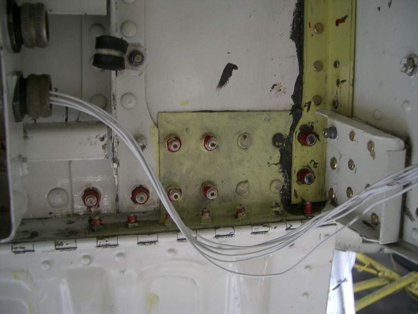
Figure 5. (a) average static shear strength of fastener pins: Baseline open symbol, collar replacement
Figure 5. (a) average static shear strength of fastener pins: Baseline open symbol, collar replacement
filled symbol (error bars represent ±1 standard deviation); and (b) shear failure of fastener pin (washer
filled symbol (error bars represent ±1 standard deviation); and (b) shear failure of fastener pin
shown at left).
(washer shown at left).
3.2. Static Tensile Strength
3.2 Static Tensile Strength
For the static tension tests, ten baseline specimens and ten experimental specimens were tested
For the
to failure. staticand
Baseline tension tests, collar
repeated ten baseline specimens
replacement andfor
results tenstatic
experimental specimens
tensile strength were tested
are compared
in Figure 6a. All measured tensile strength values exceed the published tensile strength of compared
to failure. Baseline and repeated collar replacement results for static tensile strength are 3000 lbf
in Figure 6a. All measured tensile strength values exceed the published tensile strength of 3000 lbf
(16.5 kN) for the HL70-8 collar [14]. All test specimens failed in tear-out of the aluminum collar, as
shown in Figure 6b.filled symbol (error bars represent ±1 standard deviation); and (b) shear failure of fastener pin
(washer shown at left).
3.2 Static Tensile Strength
MetalsFor the
2019, static tension tests, ten baseline specimens and ten experimental specimens were tested
9, 445 10 of 16
to failure. Baseline and repeated collar replacement results for static tensile strength are compared
in Figure 6a. All measured tensile strength values exceed the published tensile strength of 3000 lbf
(16.5 kN)
(16.5 kN) for
for the
theHL70-8
HL70-8collar
collar[14].
[14].All
All test
test specimens
specimens failed
failed in in tear-out
tear-out of the
of the aluminum
aluminum collar,
collar, as
as shown in Figure
shown in Figure 6b. 6b.
Metals 2019, 9, x FOR PEER REVIEW 10 of 16
Figure 6. (a) Average static tensile strength of fasteners: Baseline open symbol, collar replacement
filled symbol (error bars represent ±1 standard deviation); and (b) collar failure of fastener
Figure 6. (a) Average static tensile strength of fasteners: Baseline open symbol, collar replacement
assembly.
filled symbol (error bars represent ±1 standard deviation); and (b) collar failure of fastener assembly.
3.3 Shear
3.3. Shear Fatigue
Fatigue Life
Life
For the
For theshear
shear fatigue
fatigue tests,
tests, six baseline
six baseline specimens
specimens and fiveand five repeated
repeated collar replacement
collar replacement specimens
specimens
were tested were tested
to failure in atoservo-hydraulic
failure in a servo-hydraulic test system.
test system. Specimens wereSpecimens were
subjected to subjectedshear
a maximum to a
fatigue load, Ps = 900 lbf (4.0 kN) with a load ratio, R = 0. Baseline and repeated collar replacement
maximum shear fatigue load, Ps = 900 lb f (4.0 kN) with a load ratio, R = 0. Baseline and repeated
collar
test replacement
results for sheartest results
fatigue lifefor
areshear fatigue
compared life are7.compared
in Figure in Figure failed
All test specimens 7a. Allintest specimens
fatigue of the
failed in fatigue
aluminum of the
substrate, asaluminum substrate,
shown previously inas shown
Figure 4b.previously in Figure 4b.
Figure 7. Average shear fatigue life of specimens: Baseline open symbol, collar replacement filled
Figure 7. Average shear fatigue life of specimens: Baseline open symbol, collar replacement filled
symbol (error bars represent ±1 standard deviation, assuming a log-normal fatigue life distribution).
symbol (error bars represent ±1 standard deviation, assuming a log-normal fatigue life distribution).
3.4. Clamping Force
3.4 Clamping Force
For each of the collar replacement tests in static shear, static tension, and shear fatigue, the clamping
force For
waseach of thefrom
estimated collar
thereplacement tests in static
measured tightening shear, static
and loosening tension,
torques, and shear
as described fatigue, the
previously.
clamping
Clamping force results for the static shear tests are summarized in Figure 8a. A timedescribed
force was estimated from the measured tightening and loosening torques, as interval
previously.
of approximately 30 days elapsed between the initial collar installation and removal (collar 1),
Clamping time-dependency
and significant force results for the static
was shear
evident teststhe
from areinitial
summarized
clampinginforce
Figure 8a. AThis
results. timewas
interval of
due to
approximately 30 days elapsed between the initial collar installation and removal (collar
changes in the coefficient of friction between the collar and the substrate due to material relaxation. 1), and
significant
To mitigate time-dependency was evident
these effects, all subsequent frominstallations
collar the initial clamping force were
and removals results. This waswithout
conducted due to
changes in the coefficient of friction between the collar and the substrate due to material relaxation.
To mitigate these effects, all subsequent collar installations and removals were conducted without
delay, eliminating any experimental uncertainty related to time-dependent evolution of the
clamping force. Statistical analysis of the results was conducted using experimental data from
collars 2 to 5 only, due to the unreliable time-dependent results from the first collar replacement.
Clamping force results for the static tensile tests are summarized in Figure 8b. There were aMetals 2019, 9, 445 11 of 16
delay, eliminating any experimental uncertainty related to time-dependent evolution of the clamping
force. Statistical analysis of the results was conducted using experimental data from collars 2 to 5 only,
due to the unreliable time-dependent results from the first collar replacement.
Metals 2019, 9, x FOR PEER REVIEW 11 of 16
Figure
Figure 8. Average
8. Average clamping
clamping force
force vs.vs.number
numberofofcollar
collarinstallations
installations for
for (a)
(a) static
staticshear
sheartests;
tests;(b)
(b)static
static
tension
tension tests
tests andand
(c)(c) shear
shear fatigue
fatigue tests(error
tests (errorbars
barsrepresent
represent±1 ±1 standard deviation).
deviation).
Note that a direct comparison between static shear (Figure 8a) and static tension (Figure 8b)
results is not appropriate, given the different compliance of the steel and aluminum substrate of theMetals 2019, 9, 445 12 of 16
Clamping force results for the static tensile tests are summarized in Figure 8b. There were a
small number of outliers in the initial collar replacement (collar 1) torque measurements, caused by an
unfortunate rotation of the test jig within the test fixture during collar installation. For subsequent
collar installations, the tensile test specimens were tightly torqued into the fixture to prevent rotation.
Note that a direct comparison between static shear (Figure 8a) and static tension (Figure 8b) results
is not appropriate, given the different compliance of the steel and aluminum substrate of the shear and
tensile test specimens. Clamping force results for the shear fatigue tests are summarized in Figure 8c.
4. Discussion
4.1. Static Shear Strength
All static shear specimens exceeded the minimum published single shear strength of 4650 lbf
(20.8 kN) for the HL19/51-8 fastener pin [13]. Between all specimens, the average ultimate shear
strength is 4871 lbf (21.7 kN), exceeding published values with a percent difference of 8.2%. For the
specimens subjected to repetitive collar replacement, a 1.2% increase in average shear strength is
observed, relative to the baseline fastener tests. While this increase is small, it is statistically significant
due to the extremely narrow scatter of experimental test results, with a t-test probability value of 0.014.
This value implies only a 1.4% probability of achieving this result through random statistical variation
within the sample. Because there is no clear mechanism to justify an increase in static shear strength
of the fastener pin as a result of collar replacement, this result is assumed to represent a statistical
anomaly rather than an actual increase in static shear strength.
4.2. Static Tensile Strength
All static tensile test specimens exceed the minimum published tensile strength of 3000 lbf (16.5 kN)
for the HL70-8 collar [10]. Between all specimens, the average ultimate tensile strength is 3419 lbf
(15.2 kN), exceeding published values with a percent difference of 14.0%. For the specimens subjected
to repetitive collar replacement, a 1.3% increase in average tensile strength is observed, relative to
the baseline fastener tests. This increase is similar in magnitude to the increase seen for static shear
strength, but is less statistically significant due to the wider scatter of the observed tensile strength
results, with a t-test probability value of 0.092.
Due to the lower tensile strength of the aluminum collar, as compared to the steel fastener pins,
all static tensile test specimens are critical in collar failure. Even with repetitive collar replacement,
the static tensile strength of the fastener pin does not become the limiting factor for the overall tensile
strength of the fastener. Because there is no clear mechanism to justify an increase in static tensile
strength as a result of collar replacement, this result is not believed to represent a meaningful increase in
static tensile strength. Regardless, there is no decrease in static tensile strength as a result of repetitive
collar replacement for the fasteners in this test.
While static tensile tests are conducted in steel (rather than aluminum) test fixtures due to fatigue
and strength requirements, this is seen to be a conservative approach. Estimated clamping force in
the steel test specimens is found to be roughly 20% higher than for the aluminum shear specimens,
due to the higher stiffness of the steel substrate. Mechanical damage due to collar replacement should
therefore be higher in the steel test fixtures than in the simulated aluminum aircraft structure, providing
a conservative estimate for the impact of collar replacement on static tensile strength.
4.3. Shear Fatigue Life
For the shear fatigue specimens subjected to repetitive collar replacement, a 1.7% increase in
logarithmic fatigue life is observed relative to the baseline test specimens, representing an increase in
average fatigue life from 560,000 to 682,000 cycles. Given the typically observed scatter in fatigue test
results, this small experimental increase does not represent a statistically significant variation in theMetals 2019, 9, 445 13 of 16
fatigue life of the joint, with a t-test probability value of 0.265. There is no decrease in shear fatigue life
as a result of repetitive collar replacement for the fastened joints in this test.
Due to the much lower fatigue strength of the 7075-T6 aluminum substrate, as compared to the
160 ksi (1100 MPa) steel fastener pins, all shear fatigue test specimens failed by fatigue and fracture of
the aluminum sheet. The shear fatigue life of the fastener pin does not become the limiting factor for
the overall shear fatigue life of the specimen.
The applied 900 lbf (4.0 kN) constant-amplitude maximum shear fatigue load for these tests is
140% of the design limit load for the fasteners at Critical Point 16 on the CP140 aircraft [10]. While test
load levels are calibrated to ensure that fracture of the specimens occurred within an acceptable number
of cycles, the resulting loads are not directly reflective of the actual fatigue strength or behaviour of the
simulated aircraft structure.
4.4. Clamping Force
For static shear, static tension, and shear fatigue tests, no decrease in average clamping force is
observed as a function collar replacement. Between all collar changes, average clamping forces for each
test compare relatively well, with single-factor ANOVA probability values of 0.124, 0.482, and 0.280,
for static shear, static tension, and shear fatigue tests, respectively. These results indicate no statistically
significant variation in clamping force as a function of collar replacement.
In aluminum substrate, average clamping force of the fastener is found to be 1095 lbf (4.9 kN)
between static shear and shear fatigue tests. For the static tensile tests, conducted in steel fixtures,
the average clamping force of 1296 lbf (5.7 kN) is 18.4% higher, due to the higher stiffness of the steel
substrate. For all tests, estimated clamping force results are highly consistent, with standard deviations
well below the 17% uncertainty expected from [7].
5. Conclusions
In this project, Hi-Lok fasteners were subjected to multiple collar replacements and tested to
failure under static loading and constant-amplitude fatigue loading. The aim of this research was
to determine the effect of repetitive collar replacement on the residual strength and fatigue life of a
retained Hi-Lok-type fastener pin. Experimental tests were conducted for static shear, static tension,
and shear fatigue. In each case, the results from baseline test specimens were compared to those
for identical specimens subjected to five collar replacements, simulating periodic replacement of the
fastener collar in a section of fatigue-prone structure for scheduled NDI over the life of an aircraft.
From these tests, static shear results showed no decrease in the ultimate shear strength of the
fastener pin as a function of collar replacement. Static tensile results showed no decrease in the ultimate
tensile strength of the fastener as a function of collar replacement, with failure of the aluminum
collar remaining the critical failure mode. Similarly, shear fatigue results showed no decrease in the
shear fatigue life of the fastened joint as a result of collar replacement, with fracture of the aluminum
substrate remaining the critical failure mode. For static shear, static tension, and shear fatigue tests,
estimated clamping force was highly consistent between specimens and no decrease in clamping force
was observed as a function of collar replacement.
The experimental results from this project suggest that deformations and mechanical damage
resulting from a limited number of collar replacements over the life of an aircraft do not adversely affect
the residual static strength, shear fatigue life, or clamping force of retained fastener pins. Although
experimental results support retention of the fastener pin as a safe practice, important practical
considerations such as the elevated risk of mechanical damage to the fastener pin and potential
corrosion issues linked to repetitive collar removal were outside the scope of this project.Metals 2019, 9, 445 14 of 16
Author Contributions: D.F.H. performed the research in partial fulfillment of his MEng. degree in aerospace
vehicle design with D.L.D. as the project supervisor and administrator. The individual contributions of the
authors were as follows: Conceptualization, D.F.H. and D.L.D.; methodology, D.F.H.; validation, D.F.H.; formal
analysis, D.F.H.; investigation, D.F.H.; resources, D.F.H. and D.L.D.; data curation, D.F.H.; writing—original draft
preparation, D.F.H.; writing—review and editing, D.L.D.; supervision, D.L.D.; project administration, D.L.D.;
funding acquisition, D.L.D.
Funding: Financial support of this research through the Department of National Defence, AERAC and the Natural
Sciences and Engineering Research Council of Canada Discovery Grant # 239174 is gratefully acknowledged.
Conflicts of Interest: The authors declare no conflict of interest.
Nomenclature
A = dimensionless constant
D = diameter (fastener or hole)
d2 = basic pitch diameter of the thread
di = inner bearing diameter of the nut
do = outer bearing diameter of the nut
E = elastic modulus
F = clamping force
Fsu = ultimate shear stress
Ftu = ultimate tensile stress
p = pitch of the threads
Ps = shear load
Psu = ultimate single shear strength
Ptu = ultimate tensile strength
Ton = tightening torque
Toff = loosening torque
β = half-included angle of the threads
ε = strain
µt = coefficient of friction for the thread
µe = coefficient of friction for the nut face
Appendix A. Tabulated Experimental Values
The experimental data recorded for all specimens in this study are included in this Appendix A.
Table A1. Experimental data for static shear strength of fastener pins—Figure 5.
Ultimate Shear Strength (kN)
Ordered Specimens
Baseline Tests Collar Replacement Tests
1 21.15 21.64
2 21.24 21.64
3 21.39 21.66
4 21.45 21.74
5 21.46 21.81
6 21.65 21.83
7 21.67 21.85
8 21.84 21.88
9 21.87 21.90
10 - 21.99Metals 2019, 9, 445 15 of 16
Table A2. Experimental data for static tensile strength—Figure 6.
Ultimate Tensile Strength (kN)
Ordered Specimens
Baseline Tests Collar Replacement Tests
1 14.62 14.91
2 14.83 14.93
3 14.83 15.26
4 15.08 15.32
5 15.09 15.35
6 15.24 15.37
7 15.26 15.40
8 15.32 15.43
9 15.40 15.50
10 15.43 15.61
Table A3. Experimental data for shear fatigue life—Figure 7.
Shear Fatigue Life
Ordered Specimens Baseline Tests Collar Replacement Tests
Cycles Cycles
1 299,375 477,080
2 459,220 540,172
3 478,433 712,686
4 579,463 833,426
5 679,867 846,124
6 864,655 -
Table A4. Experimental data for clamping force for static shear tests—Figure 8a.
Estimated Clamping Force (kN)
Ordered Specimen
Collar 1 Collar 2 Collar 3 Collar 4 Collar 5
1 2.16 3.61 3.37 4.09 4.27
2 2.48 3.69 3.74 4.26 4.44
3 3.17 4.19 3.97 4.55 4.49
4 3.51 4.33 4.19 4.55 4.55
5 3.51 4.38 4.46 4.75 4.68
6 3.61 4.75 4.53 5.03 4.75
7 3.66 4.76 4.55 5.10 5.07
8 3.72 4.79 4.59 5.15 5.10
9 4.61 5.01 4.85 5.35 5.16
10 5.10 5.45 5.05 - 5.40
Table A5. Experimental data for clamping force for static tensile tests—Figure 8b.
Estimated Clamping Force (kN)
Ordered Specimen
Collar 1 Collar 2 Collar 3 Collar 4 Collar 5
1 4.18 3.81 5.03 4.18 4.64
2 4.36 4.90 5.18 4.88 4.79
3 4.93 5.03 5.32 5.33 4.90
4 5.03 5.23 5.48 5.48 5.67
5 5.33 5.79 5.80 5.77 5.72
6 5.70 5.95 5.95 5.80 6.39
7 6.67 6.20 5.99 6.34 6.45
8 - 6.42 6.12 6.82 6.62
9 - 6.45 6.24 6.93 6.82
10 - 7.86 7.49 8.57 8.05Metals 2019, 9, 445 16 of 16
Table A6. Experimental data for clamping force for shear fatigue tests—Figure 8c.
Estimated Clamping Force (kN)
Ordered Specimen
Collar 1 Collar 2 Collar 3 Collar 4 Collar 5
1 4.29 3.52 4.18 4.39 4.90
2 4.41 4.53 5.28 4.68 5.05
3 4.64 4.88 5.65 5.13 5.07
4 4.75 5.20 5.70 5.48 5.23
5 5.68 5.30 7.11 5.92 6.02
References
1. Lisi Aerospace. Hi-Lok Collar. Available online: http://www.lisi-aerospace.com/products/fasteners/internally-
threaded/collars/Pages/nut-hi-lok.aspx (accessed on 5 March 2019).
2. Hi-shear Corporation. Hi-Lok/Hi-Tigue Fastening Systems: Installation Instructions; Hi-Shear Corporation:
Torrance, CA, USA, 1991.
3. C-12-140-012/TR-001-Repair Instructions-CP140 Aurora/CP140A Arcturus-Structural Volume 1.
4. Fahr, A.; Wallace, W. Aeronautical Applications of Non-Destructive Testing; DEStech Publications, Inc.: Lancaster,
PA, USA, 2014.
5. Jones, R.; Molent, L.; Pitt, S. Understanding Crack Growth in Fuselage Lap Joints. Theor. Appl. Fract. Mech.
2008, 49, 38–50. [CrossRef]
6. Director General of Aerospace Engineering and Project Management. RMC 2005-007-SLA, -DGAEPM 482147
Request for Research, Scientific, and Technical Assistance from Royal Military College; DGAEPM: Ottawa, ON,
Canada, 2006.
7. Heshavanarayana, S.; Smith, B.L.; Gomez, C.; Caido, F. Fatigue-Based Severity Factors for Shear-Loaded
Fastener Joints. J. Aircr. 2010, 47, 81–191.
8. Li, C.; Su, H. The Influence of Pre-tension Load in the Composite Laminate Fastener Joint During Repeated
Tightening. In Proceedings of the 21st International Conference on Composite Materials, Xi’an, China,
20–25 August 2017.
9. IMP Aerospace. DWG # 939529-CA40; IMP Aerospace: Enfield, NS, Canada, 2010.
10. Lockheed Martin Corporation. STP52-726; Lockheed Martin Corporation: Bethesda, MD, USA, 2010.
11. LISI Aerospace. HL19 Hi-Lok Pin Data Sheet. Available online: http://www.lisi-aerospace.com/products/
Pages/Fasteners-Catalog.aspx (accessed on 5 March 2019).
12. Eccles, W. A New Approach to the Checking of the Tightness of Bolted Connections; Lubrication, Maintenance,
and Tribotechnology; Paper Number: L144056; LUBMAT 2014: Manchester, UK, 2014.
13. Eccles, W. A New Approach to the Tightness Checking of Bolts. Fastener + Fixing Magazine; Issue 90.
2014. Available online: http://boltscience.com/pages/a-new-approach-to-the-tightness-checking-of-bolts.pdf
(accessed on 5 March 2019).
14. LISI Aerospace. HL70 Hi-Lok Collar Data Sheet. Available online: http://www.lisi-aerospace.com/products/
Pages/Fasteners-Catalog.aspx (accessed on 5 March 2019).
© 2019 by the authors. Licensee MDPI, Basel, Switzerland. This article is an open access
article distributed under the terms and conditions of the Creative Commons Attribution
(CC BY) license (http://creativecommons.org/licenses/by/4.0/).You can also read