Effects of resonant magnetic perturbations on radial electric fields in DIII-D tokamak
←
→
Page content transcription
If your browser does not render page correctly, please read the page content below
© 2021 Hefei Institutes of Physical Science, Chinese Academy of Sciences and IOP Publishing   Printed in China and the UK             Plasma Science and Technology

Plasma Sci. Technol. 23 (2021) 105104 (13pp)                                                                                https://doi.org/10.1088/2058-6272/ac190e

Effects of resonant magnetic perturbations
on radial electric fields in DIII-D tokamak
Jingyuan FU (付敬原)1 , Pengfei LIU (刘鹏飞)2, Xishuo WEI (魏西硕)2,
Zhihong LIN (林志宏)2, Nathaniel Mandrachia FERRARO3 and
Raffi NAZIKIAN3
1
  Fusion Simulation Center, Peking University, Beijing 100871, People’s Republic of China
2
  Department of Physics and Astronomy, University of California, Irvine, CA 92697, United States of
America
3
  Princeton Plasma Physics Laboratory, Princeton, NJ 08543, United States of America

E-mail: zhihongl@uci.edu

Received 13 April 2021, revised 27 July 2021
Accepted for publication 29 July 2021
Published 27 August 2021

Abstract
Gyrokinetic simulations of DIII-D tokamak equilibrium find that resonant magnetic perturbation
(RMP) drives a neoclassical non-ambipolar electron particle flux, which causes a rapid change of
equilibrium radial electric fields consistent with experimental observations during the
suppression of the edge localized mode (ELM). The simulation results provide a support for the
conjecture that RMP-induced changes of radial electric fields lead to the enhanced turbulent
transport at the pedestal top during the ELM suppression (Taimourzadeh et al 2019 Nucl. Fusion
59 046005). Furthermore, gyrokinetic simulations of collisionless damping of zonal flows show
that resonant responses to the RMP decrease the residual level of the zonal flows and damp the
geodesic acoustic mode.
Keywords: resonant magnetic perturbation, neoclassical transport, zonal flow, electric field
(Some figures may appear in colour only in the online journal)

1. Introduction                                                                       change much more slowly during the transition to the ELM
                                                                                      suppression. An outstanding issue is that how the 3D RMP
In tokamak high-confinement regime (H-mode) with an edge                               causes the rapid change of the equilibrium radial electric fields.
transport barrier, edge localized modes (ELM) [1] are often                                The short timescale of the rapid flow damping implies
observed to drive a large energy flux from the pedestal region to                      that the magnetohydrodynamic (MHD) braking effect [12]
plasma-facing components [2]. The resonant magnetic pertur-                           does not make the dominant contribution. Beyond the MHD
bations (RMP), produced by a set of external coils, have been                         theory, several kinetic theories have been proposed to explain
showed to be effective for ELM suppression/mitigation [3–8].                          the toroidal torque induced by the 3D RMP. In particular,
The mode stability analysis [3, 4] shows that the RMP can                             neoclassical toroidal viscosity (NTV) theory [13–15] suggests
stabilize the ELM by enhancing the radial particle transport at                       that the 3D RMP can induce a radial transport of trapped
the pedestal top, thus preventing the pedestal from reaching the                      particles, which generates a toroidal braking torque. Quali-
stability boundary. However, the mechanism for the enhanced                           tative agreement has been obtained [16–20] between the NTV
particle transport at the pedestal top, i.e. density pump-out is not                  theory and the braking torque measured in the experiments,
well understood [5, 9]. Meanwhile, a rapid damping of toroidal                        but a quantitative discrepancy persists. More importantly,
flows at the pedestal top [10] is often observed during the                            prediction of the particle pump-out associated with the
transition from ELMing to ELM suppression state. This flow                             enhanced particle fluxes requires self-consistent calculation of
damping plays an important role in the turbulent transport that                       the ambipolar electric fields, which have not been considered
causes the density pump-out at the pedestal top in a DIII-D shot                      in the NTV theory [21].
[11]. The flow damping is mostly caused by a rapid change of                                Recently, gyrokinetic simulations have made impressive
equilibrium radial electric fields since plasma pressure profiles                       progress studying neoclassical and turbulence transport in

1009-0630/21/105104+13$33.00                                                      1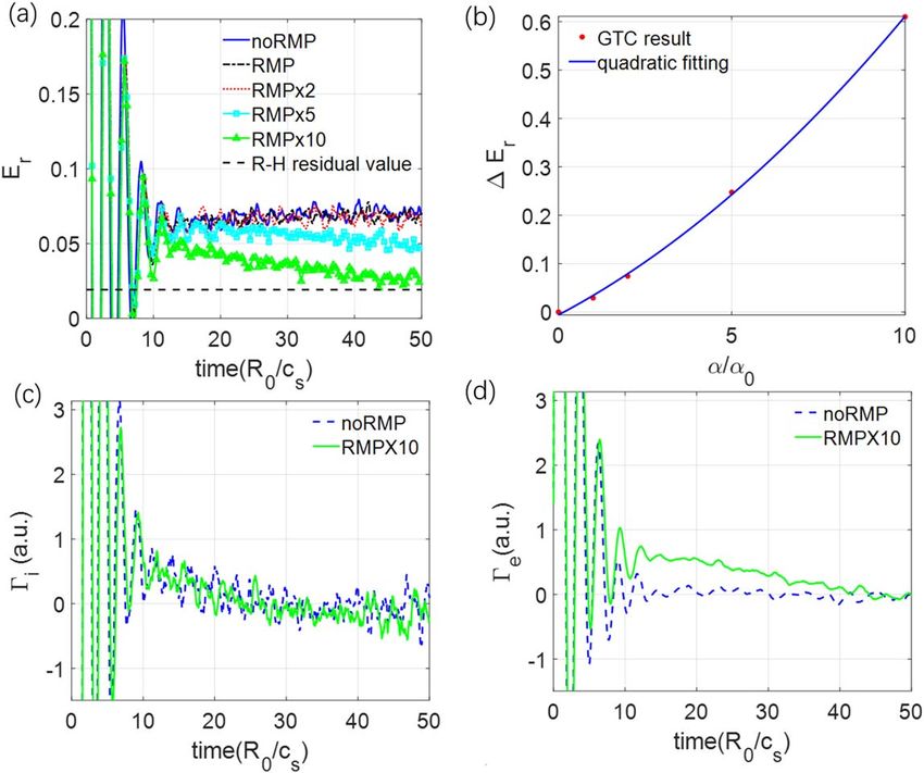
Plasma Sci. Technol. 23 (2021) 105104 J Fu et al
tokamak with 3D RMP. Gyrokinetic RMP simulations initi- rapid change of equilibrium radial electric fields consistent
ally used vacuum magnetic field generated by the I-coil with experimental observations during the transition from the
without plasma responses [22–25]. A gyrokinetic quasilinear ELMing to ELM suppression state. The GTC neoclassical
theory [26] predicts an enhanced transport in the pedestal simulation results on the pedestal top are in qualitative
region due to the reduction of the RMP shielding by the agreement with the XGC neoclassical simulation results near
reversal of the equilibrium radial electric field on a resonant the magnetic separatrix [30] and provide a support for the
surface. However, the plasma responses greatly affect the conjecture that RMP-induced changes of radial electric fields
RMP penetration and magnetic island formation [27], which lead to enhanced turbulent transport at the pedestal top during
need to be taken into account in the gyrokinetic simulations of the ELM suppression [11, 31]. Furthermore, GTC simulations
neoclassical and turbulent transport. Indeed, gyrokinetic GTC of collisionless damping of zonal flows find that resonant
[28] simulations of a DIII-D tokamak equilibrium with responses to the RMP decrease the residual level and damp
plasma non-resonant responses to the RMP find that the 3D the geodesic acoustic mode (GAM).
equilibrium with closed flux-surfaces does not enhance tur- The rest of the paper is organized as follows. GTC
bulence transport since the RMP amplitude is too small to neoclassical simulation model for the tokamak equilibrium
have significant effects on linear drift-wave instability or with the 3D RMP is formulated in section 2. Simulations of
zonal flow damping [29]. Further GTC simulations find that neoclassical transport with the RMP without and with equi-
the reduction of the radial electric field shear at the top of the librium electric field are presented in sections 3 and 4,
pedestal during ELM suppression leads to enhanced micro- respectively. In section 5, we calculate the time rate of change
turbulence and extended turbulence spreading to the top of of the equilibrium radial electric field due to the non-ambi-
the pedestal relative to ELMing plasmas with similar RMP polar electron particle fluxes. Effects of the 3D RMP on the
and pedestal parameters (see figures 5–8 of [11]). collisionless damping of zonal flows are discussed in
Subsequently, gyrokinetic XGC simulations use the DIII- section 6. Finally, conclusions and discussions are discussed
D equilibrium with both resonant and non-resonant responses in section 7.
to the RMP to study the neoclassical transport in a short time
scale before the ELM suppression, and show that non-ambi-
polar neoclassical transport can cause a rapid change of radial 2. Formulation of neoclassical simulation in tokamak
electric fields Er near the magnetic separatrix [30], which with 3D RMP
leads to the enhanced turbulent transport [31] in agreement
with the earlier GTC results [11]. However, the mechanism of 2.1. Implementation of tokamak equilibrium with 3D RMP
the fast Er change (i.e. the driving term) has not been carefully in GTC
studied in a long time range from the ELMing to ELM sup-
pression state, and the simulation results of the Er change In this work, GTC simulations use magnetic equilibrium with
have not been compared with experimental value carefully. full plasma response to RMP, including both non-resonant
Furthermore, the stochastic region near the separatrix plays an response (which preserves closed flux surfaces) and resonant
important role in references [30, 31], while the focus of this response (which creates magnetic islands and/or magnetic
paper is on the pedestal top and there is no global stochasti- stochasticity) calculated by the resistive MHD code M3D-C1
city from the pedestal top to the separatrix. We point out that [42]. The equilibrium profiles [10, 11, 29] from the DIII-D
the fast electron flux along the stochastic field line is mostly discharge #158103 at 3050 ms, when ELM is suppressed by
heat flux (i.e. Rechester–Rosenbluth theory [32]), but the the n=2 RMP, are chosen as the base case for GTC
RMP induces the density pump-out while temperature profile simulations.
changes little. The equilibrium magnetic field can be written as
In this work, we use GTC simulations to study the RMP B=B0+δB, where B0 represents the equilibrium magnetic
effects on the radial electric fields including both equilibrium field of an axisymmetric tokamak and δB represents the 3D
electric fields associated with toroidal rotations and zonal RMP. In GTC, the Boozer coordinate (y, q, z ) is used,
flows generated by microturbulence, which greatly affect the corresponding to poloidal magnetic flux, poloidal and toroidal
turbulent transport in tokamaks. Several theories have studied angles. The equilibrium magnetic field can then be repre-
the effects of the RMP on the zonal flow damping [33–35]. se=riant form: B0 = d y + g z + I q = q y ´ q +
However, the validity of these theories should be verified with z ´ y. Here, q is the safety factor, 2pg and 2pI are
the gyrokinetic simulations. GTC simulations of the micro- poloidal and toroidal currents, and δ represents the components
turbulence and neoclassical transport in 3D toroidal geometry of the currents that depend on the poloidal angle. The perturbed
including stellarators [36, 37] and tokamaks with 3D magn- magnetic field is cast in GTC using a reduced form
etic fields [11, 29, 38–41] have been extensively verified. d B = ´ (aB0 ), which preserves the radial component of
GTC simulations reported in this paper use realistic DIII-D perturbed field. The M3D-C1 provides the Fourier series
tokamak equilibrium with both resonant and non-resonant a = å m, namn einz - imq , where amn is the coefficient of the
responses to the 3D RMP calculated by the resistive MHD Fourier series. The function α calculated by this Fourier series
code M3D-C1 [42]. Neoclassical simulation results show that is then converted to a 3D spline function in GTC [29, 43].
RMP-induced magnetic islands and stochastic electron orbits Figure 1(a) shows the Poincare plot of the equilibrium
drive a non-ambipolar electron particle flux, which leads to a magnetic field with the 3D RMP at the z = 0 poloidal plane,
2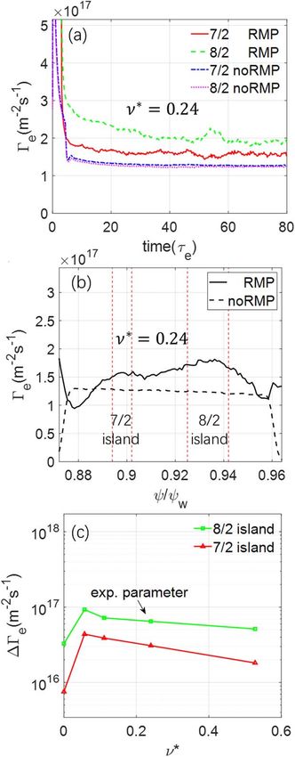
Plasma Sci. Technol. 23 (2021) 105104 J Fu et al
Figure 1. (a) Poincare plots on the z = 0 poloidal plane for magnetic field lines (small points), and deuterium gyrocenter orbits (red, blue and
green big points) for three different pinch angles λ with local thermal speed. Here, qgeo (rad) is geometric poloidal angle. (b) Spectrum of
n=2 RMP magnetic field as a function of poloidal harmonic m and poloidal flux y. Dashed red line represents resonant response. (c) Radial
profiles of perturbed magnetic fields Bmn , where the red rectangular box is enlarged in panel (d).
where y is normalized with its value yw at the last closed flux island width around the q = 4 rational flux surface, the RMP
surface. In the region between y = (0.87–0.97) yw, three islands should not affect the ion neoclassical transport sig-
island chains (m /n ) = (-7 /2), (-8 /2), (-9 /2) are clearly nificantly [30, 45] due to gyroaveraging and guiding center
separated by Kolmogorov–Arnold–Moser surfaces. The orbit averaging effects, especially when comparing with the
Chirikov parameter (defined in equation (2) in [44]) at q = 4 dominant role of the magnetic separatrix in regulating the ion
rational flux surface is 0.33. While there is very little sto- neoclassical transport. Therefore, we neglect the effect of
chasticity of the magnetic field lines, the particle orbits may RMP on the ion dynamics, and only study the single-species
still possess some stochasticity due to the cross-field guiding neoclassical transport of the electron in this work.
center drifts that sample multiple magnetic islands. The island Figure 1(b) shows the poloidal spectrum of the perturbed
widths in the high field side are, respectively, 0.5, 1.5 and 1 in
ò ò J (d B · y) eimq-inz dz dq, where
1
magnetic field Bmn =
the unit of local proton Larmor radius. Since the 8/2 island is A
the largest, we focus on the physics around the q = 4 rational A is the surface area of the magnetic flux surface and J is the
flux surface (y = 0.93yw ). Jacobi of the coordinates. The plasma response could be
Figure 1(a) also shows the Poincare plot for deuterium separated into the resonant response and non-resonant
gyrocenter orbits around the y = 0.95yw flux surface with response. The resonant response could be quantified by the
mB magnitude of the perturbed magnetic field at rational surfaces,
three different pinch angles l º E =0.3, 0.5 and 0.9, which
correspond to the typical passing particle, barely trapped represented by the red dashed line where q = m /n. The
particle, and deeply trapped particle, respectively. The guid- negative m of resonant responses indicates the left-handed
ing center orbits in the region outside of y = 0.95yw could helicity of the plasma currents.
be strongly affected by the magnetic separatrix of the divertor, Figure 1(c) shows the radial profiles of several poloidal
which is then expected to play the dominant role in the ion harmonics of the RMP. The vertical dashed lines correspond
neoclassical transport in the pedestal [30]. Since the widths of to the radial positions of different rational surfaces. The
the ion guiding center orbits are much larger than the RMP horizontal short lines correspond to the vacuum RMP field
3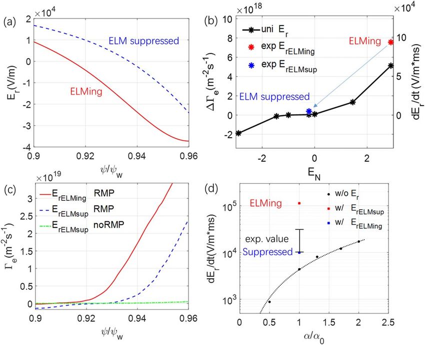
Plasma Sci. Technol. 23 (2021) 105104 J Fu et al
values at the rational surfaces. Figure 1(d) shows the enlarged Here, we assume that the potential f (y ) is only the
red rectangular region in figure 1(c), where the ratio between function of flux surface.
the resonant response and the vacuum RMP field value at the The equilibrium distribution function is defined by
q = 4 rational surface is about 0.1, which indicates that the L 0 f0e = 0. (2 )
RMP is strongly screened by the plasma response.
Since the collision operator in L 0 will relax the electron
2.2. GTC simulation model of neoclassical transport with RMP distribution function to the Maxwellian in the ion frame, the
and radial electric field solution of f0e is a shifted Maxwellian
3
In the GTC neoclassical simulations, the dynamics of electron m 2 2mB0 + m e (v - v 0 )2 ⎞
gyrocenter are calculated by the Hamiltonian [46] in the phase f0e = fSM = n e ⎛ e ⎞ exp ⎛⎜ -
⎜ ⎟ ⎟,
⎝ 2pT0e ⎠ ⎝ 2T0e ⎠
space (X, E , m ),
m v2
where n e (y, q ) = n 0e (y ) exp ⎛ 2T 0 ⎞ and T0e (y ) are the equi-
e
1
H = E - ef = m e v2 + mB - ef , ⎝ 0e ⎠
2 librium density and temperature profiles. The v 0 is the equili-
where X is the spatial coordinates, E is the particle kinetic brium ion toroidal rotation, which is determined by the ion radial
energy, μ is the magnetic moment. m e is the mass of electron,
-e is the charge of electron, v is the parallel velocity along
force balance v 0 =
g
W
B0 t
= -B
cg
0
( ), where the ion pressure
¶f
¶y
gradient is neglected, g = RBz , R is the major radius, Bz is the
the field line, B is the amplitude of magnetic field, and f is the toroidal component of the magnetic field B0 , Wt is the angular
electrostatic potential. velocity of the ion toroidal rotation. For single-species simula-
The drift kinetic equation describing the guiding center tions of the electrons, the density n e is assumed to be a function
equations of motion based on this Hamiltonian with static of flux surface only, since v 0 v e.
magnetic perturbations takes the form The perturbed distribution function obeys the following
perturbed drift kinetic equation
¶fe dB
L ( fe ) º + ⎛vb0 + vd + vE + v ⎞
dB ⎛
⎜ ⎟
¶t ⎝ B0 ⎠ L (dfe ) = -dLf0e = vd · kfSM + v · k+
e
⎜ f⎞ fSM .
⎟
B0 ⎝ T0e ⎠
⎡ ¶f ¶f ⎤
·⎢⎛ e ⎞ + e f ⎛ e ⎞ ⎥ - C ( fe ) = 0, (1 ) (3 )
¶X ⎠ E, m ⎝ ¶E ⎠X, m ⎦
⎣⎝
Here, higher order terms in v 0 /v e are neglected and the
where fe is the electron gyrocenter distribution function, equilibrium gradient parameter is defined as
B
b0 = B0 , C denotes the Fokker–Plank collision operators,
2mB0 + m (v - v 0 )2 3
k º ⎛⎜kn + ⎛⎜
0
which include inter-species and like-species collisions that - ⎞⎟ kt
conserve particle number, momentum and energy [47]. ⎝ ⎝ 2T0e 2⎠
The drift velocity vd denotes the magnetic curvature and m (v - v 0 ) v 0 ⎞
gradient drifts, and vE denotes the E×B drift. In the absence + k v y, ⎟
T0e ⎠
of magnetic perturbations dB, the drift velocity could be
g Wt
written as: vd = -
cm e v2 ´ b 0
-
c m b 0 ´ B0
, and vE = c b 0 ´ f
. where k n y = - nn 0e , kt y = - TT0e , k v y = - B .
0e 0e 0 v 0
eB0* eB0* B0*
Bv
Here, c denotes the speed of light, B*0 = B0 + W ´ 2.3. Verification of GTC simulation of neoclassical transport
a
b0 , B0* = b0 · B*0 .
In this subsection, we verify simulation results of neoclassical
In GTC, the perturbative df method is used in the
transport for both an axisymmetric circular cross section
simulation of neoclassical transport [47] to reduce the particle
tokamak and the DIII-D tokamak. In the neoclassical simu-
noise. The total distribution function could be separated into
lation, uniform Maxwellian distributions of electron markers
equilibrium and perturbation part: fe = f0e + dfe . We also
are loaded over an annulus of a tokamak. Based on con-
expand the L into two parts, that is L = L 0 + dL, and
vergent studies, a total of 4.23 ´ 107 particles are used in all
¶ ⎞ the neoclassical simulations in this paper. Ions are treated as
L 0 = (vb0 + vE) · ⎛ the cold, fixed background.
⎝ ¶X ⎠ E, m
For the circular cross section tokamak, we use the repre-
¶ sentative parameters with a major radius R0 = 1.86 m, a minor
+ e (vb0 + vd) · f ⎛ ⎞ - C ( f0e ) ,
⎝ E ⎠X, m radius a = 0.246R0 , the magnetic field strength on axis
B0 = 1.35 T, uniform electron temperature profile with
¶ d B ⎡⎛ ¶ ⎞ ¶ Te = 5.0 keV, electric filed Er = 0, a safety factor profile
dL = + v · - qs f ⎛ ⎞ ⎤ y y2
¶t B0 ⎢ ⎣ ⎝ ¶X ⎠ E,m ⎝ ¶E ⎠X, m ⎥
⎦ q = 1.475 + 1.1 y + 1.0 y 2 , a density profile n e =
w w
+ vd · ⎛ ⎞ - C (dfe ).
⎝ ¶X ⎠ E, m ( y
n 0 ⎡1.0 + 0.205 ⎛tanh 0.75 - 2.5 y - 1.0⎞⎤. At r = 0.5a ,
⎣ ⎝ w ⎠⎦
)
4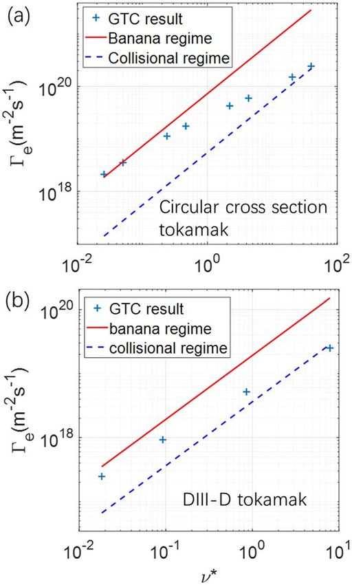
Plasma Sci. Technol. 23 (2021) 105104 J Fu et al
Figure 2. Axisymmetric equilibria of DIII-D discharge #158103 at 3050 ms. (a) Cross section between y = 0.984yw (solid line) and
y = 0.86yw (dashed line). (b) Electron density ne and temperature Te profiles, values on y = 0.86yw are 2.4 ´ 1013 cm-3 and 1.45 keV.
(c) Safety factor q and electron effective collision frequency n* profiles.
q = 2, Z eff = 1, and the gradient scale length value of density is For comparison, the analytic values of Ge in the banana regime
R0 /L n = 2.2. The effective electron collision frequency n * = and collisional regime are also plotted. For the circular cross
e-3 / 2nqR0 /vth is defined as the physical collision frequency n section tokamak, the GTC neoclassical simulation results
normalized by the bounce frequency, where e = r /R0 is the agree well with the analytic results for [47, 48] in both low
local inverse aspect ratio, vth = T0e /m e is the electron thermal and high frequency regimes. For the DIII-D tokamak, the
velocity. simulation results are slightly smaller than the analytic results
For the DIII-D tokamak, figure 2 shows the equilibrium in both frequency regimes, presumably due to the shaping and
cross section and profiles after the ELM suppression. The 2D finite aspect ratio effects neglected in the analytic theory.
plot of the simulation domain is shown in the figure 2(a). The
equilibrium n e and Te profiles are plotted in figure 2(b), q
profile and n* profiles of electron are shown in figure 2(c),
respectively. At the q = 4 rational surface, the gradient scale 3. Effects of RMP on neoclassical particle flux
length value of density and electron temperature are without equilibrium electric field
R0 /L n = 9.2 and R0 /L Te = 18, n * = 0.24, Z eff = 3, and
e = 0.27 are evaluated on the outmost midplane. The equi- We now study effects of the RMP on electron particle fluxes
librium inhomogeneity scale length at q = 4 rational surface Ge using the equilibrium and plasma parameters of the DIII-D
is larger than the poloidal ion Lamour radius, riq /L Te = 0.5, discharge #158103 as described in section 2. Since the main
and is much larger than the island width W8,2 /L Te = 0.04. In
island chains at the q = 4 rational surface are close to the
this verification simulation, the k n of electron and Te are set to
separatrix, high energy trapped ions can cross the separatrix
be uniform by using the value at q = 4 rational surface
into the scrape-off layer (SOL), as shown in figure 1(a). These
(y = 0.935yw ), which is referred to as the rigid rotation case.
Other important parameters are Er = 0, R0 = 1.76 m, the lost ions can have significant effects on the radial electric
magnetic field strength on axis B0 = 1.8 T. fields near the separatrix even without applying RMP
The neoclassical particle fluxes in the absence of the [30, 31]. The focus of this paper is to calculate the additional
RMP and electric field are simulated for various collision effects of the RMP, on top of the lost ions and the electrons.
frequencies to verify the neoclassical simulation model. The Therefore, we assume that ion and electron have already
relation between electron particle flux Ge at steady state versus achieved ambipolarity before RMP is applied. Also, only the
electrons are simulated, assuming that effects of the RMP on
n* is plotted in the figure 3, where Ge = ò vd · y dfe d3v .
the ion transport is much smaller than the electron transport.
5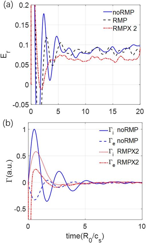
Plasma Sci. Technol. 23 (2021) 105104 J Fu et al
Figure 3. Neoclassical particle flux Ge dependence on effective
collision frequency n* without RMP and electric field under circular
cross section tokamak (panel a) and DIII-D tokamak (panel b). The
line is analytic expression in banana regime (red solid line) and
collision regime (blue dashed line).
3.1. Verification of RMP effects with rigid rotation case
In this subsection, we use the rigid rotation case to verify the
effects of the RMP on neoclassical transport, where the par-
ticle fluxes in the presence of the RMP are measured by
ò (vd + v B ) · y dfe d3v
dB
Ge = . Define the non-ambi-
0
polar particle flux induced by the RMP DGe º GRMP - G0 ,
where GRMP and G0 are the neoclassical electron particle fluxes
Figure 4. Neoclassical electron particle flux in rigid rotation case. (a)
with and without the RMP. The neoclassical particle flux in
Time history of Ge at 7/2 and 8/2 island regions in simulations with
axisymmetric tokamak G0 is intrinsically ambipolar and without RMP. (b) Ge profile averaged over t = [40, 80]te in
[38, 40, 44]. However, GRMP is not ambipolar and DGe can simulations with and without RMP. Vertical dashed lines represent
induce a change of ambipolar electric field to restore the island separatrices. (c) Dependence of DGe on collision frequency n*
at 7/2 and 8/2 island regions.
ambipolarity, similar to the neoclassical transport in stellara-
tors [37]. The electron particle fluxes reach a steady state after a few
Figure 4(a) shows the time history of volume-averaged collision times te = 1 /n . In the simulation without the RMP,
electron particle fluxes Ge around 8/2 and 7/2 island regions. there is no obvious difference between the Ge in these two
6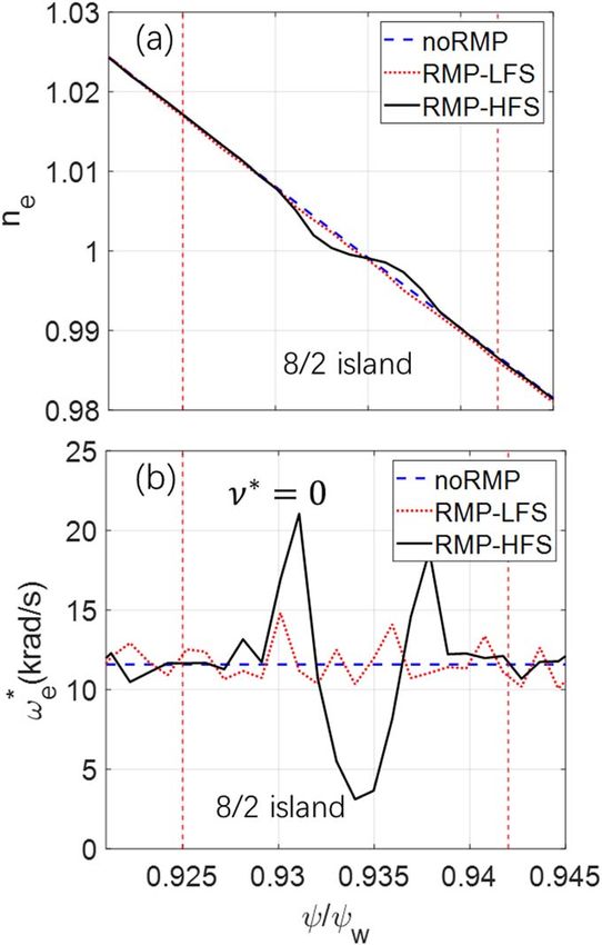
Plasma Sci. Technol. 23 (2021) 105104 J Fu et al
regions. However, in the simulation with the RMP, compared
with the 7/2 island, the wider 8/2 island induces a much
larger increase of electron particle flux DGe at steady state
t = 40te. The DGe induced by the 8/2 island is comparable to
the G0 , but is much smaller than the turbulent transport level
and therefore does not contribute to the density pump out.
However, the non-ambipolar particle fluxes can induce an
ambipolar electric field, which will be calculated in the
section 5.
Figure 4(b) shows the Ge radial profiles averaged over
t = [40, 80]te in the simulations with and without the RMP.
Three regions, the 7/2 island region (q = 3.44–3.55), the 8/2
island region (q = 3.84–4.15), and the non-resonant region
(q = 3.55–3.84), are separated by the island separatrices. The
larger 8/2 island induces a much larger DGe than those in the
7/2 island region and in the non-resonant region, which
suggests that the non-ambipolar electron particle flux is
mostly driven by the resonant component of the RMP.
Figure 4(c) shows the DGe in the simulations varying the
collision frequency n * = [0, 0.5] in the two island regions.
The DGe in the collisionless case is much smaller than that in
the simulations with collisions, which indicates that the flutter
transport due to magnetic stochasticity is not dominant [32].
The DGe in both the 7/2 and 8/2 island regions slightly
decreases with the collision frequency in the banana regime.
Figure 5(a) shows the relaxation of electron density
profiles in the 8/2 island region in the collisionless simula-
tions with and without the RMP. On the high field side, the
electron density profile is locally flattened inside the 8/2
island region and reaches the steady state after some bounce
times. On the low field side, the electron density profile is less
affected by the RMP, because the trapped particles on the low
field side do not follow the field line around the magnetic
island. In the collisional simulations, the collisions could Figure 5. Electron density profiles n e (panel a) and diamagnetic
further modify the density profiles [39]. frequency w*e profiles (panel b) in rigid rotation case in 8/2 island
Figure 5(b) shows the relaxation of electron diamagnetic region in collisionless simulations after profile relaxation. Red-
dotted and black solid lines are profiles on low field side and high
frequency w*e = - qn1 e ¶¶neyTe profiles in the 8/2 island region in field side with RMP. Blue-dashed line is profile without RMP.
e
the collisionless simulations with and without the RMP. On Vertical dashed lines represent island separatrices.
the low field side, the electron diamagnetic frequency is only
slightly affected by the RMP, which is consistent with the
change of density profile on the low field side. On the high simulations with the RMP, both uniform Te and experimental Te
field side, the electron diamagnetic frequency is significantly profiles can induce the non-ambipolar particle fluxes DGe. We
changed across the 8/2 island region, because the density rewrite the non-ambipolar particle flux DGe = D0 (k n + bkt ),
profile is flattened locally. where D0 is the transport coefficient in the uniform Te (kt =0)
case, β denotes the ratio between the contribution from
3.2. Simulation with the experimental equilibrium profiles temperature and density gradients. We find that b = 0.56,
which is qualitatively consistent with the NTV theory [13].
We now use experimental n e and Te profiles described in
The neoclassical simulations use the RMP equilibrium
section 2.3. Two sets of simulations are carried out with or
calculated by the M3D-C1, which could have a large uncer-
without the RMP. The first set uses the experimental n e
tainty in the magnetic island width. Therefore, we perform a
profile and a uniform Te = Te (q = 4), thus kt = 0. The sec-
ond set uses both the experimental n e and Te profiles as the sensitivity study for the RMP amplitude α. Figure 7 shows
equilibrium profiles. the dependence of DGe on the α on the q=4 surface from
Figure 6 shows the steady state Ge profiles in the simu- GTC neoclassical simulations using experimental equilibrium
lations. In the simulations without the RMP, the ambipolar Ge profiles, where α0 is the original RMP amplitude calculated
in the case with experimental Te (kt >0) is slightly smaller by the M3D-C1. It is clear that DGe follows a quadratic
than that in the uniform Te (kt =0) case, which qualitatively relation with α, i.e. the non-ambipolar flux is proportional to
agrees with the standard neoclassical theory [48]. In the the magnetic island width.
7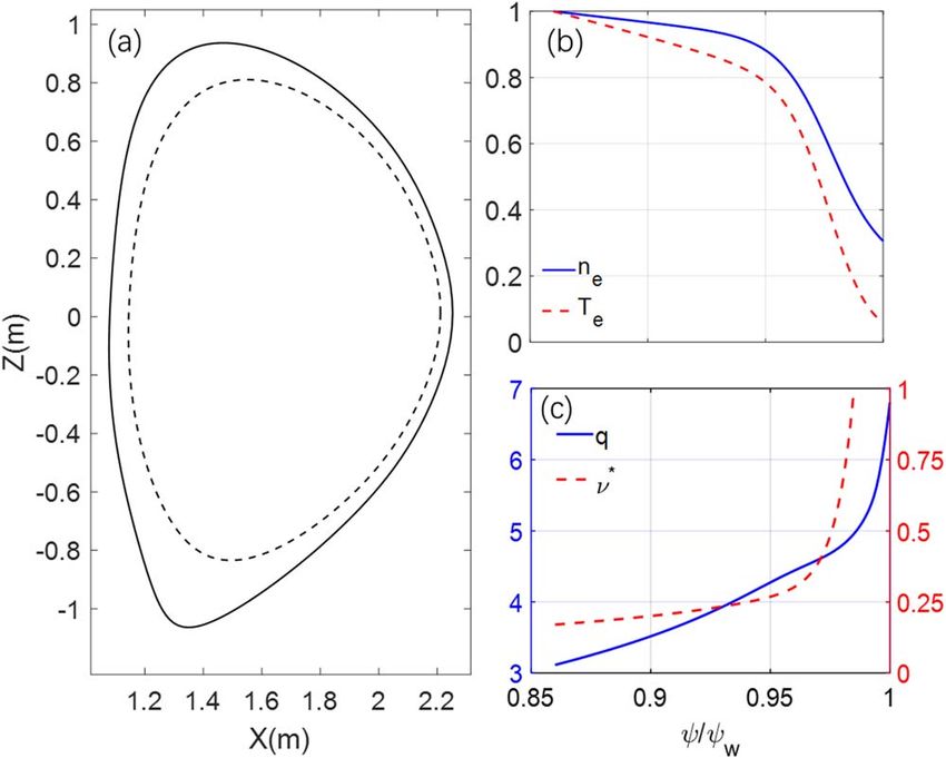
Plasma Sci. Technol. 23 (2021) 105104 J Fu et al
electric field Er can change significantly, which can affect the
neoclassical and turbulent transport [11, 31].
Figure 8(a) shows the radial profiles of the experimental
equilibrium Er on the outer midplane during the ELMing
(3796 ms) and ELM suppression (3050 ms) in the DIII-D
discharge #158103. In this section, these two Er profiles,
together with the n e and Te profiles at 3050 ms, are used as the
equilibrium. The 8/2 island width is much smaller than the
typical equilibrium inhomogeneity scale length, which allows
us to use the 1D equilibrium electric field.
First, we verify the effects of the equilibrium electric field
Er using the uniform k n and Te profiles with the value at the
¶f
q = 4 flux surface. Uniform Ey = - ¶y profiles (rigid rota-
tion case) or experimental Er profiles are used in the simu-
lations separately. Figure 8(b) shows the DGe near the q = 4
surface at the steady state of neoclassical simulations using
the equilibrium with the RMP and the uniform electric field
¶f T
Ey. Here, we use EN º - ¶y / qa k n to represent the amplitude
a
of the electric field, which corresponds to the ratio between
Figure 6. Electron particle flux Ge profiles from neoclassical
the E×B and diamagnetic flows. The EN values of 2.9 and
simulations using experimental density profile, experimental Te (lines
with ‘exp’ label) or uniform Te profiles (lines with ‘uni’ label), with −0.22 correspond to the local value of the electric field during
and without RMP (lines with ‘RMP’ and ‘noRMP’ label). Vertical the ELMing and the ELM suppression, respectively. The
dashed lines represent island separatrices. value of EN = -1 corresponds to the toroidal rotation fre-
quency Wte = 0. In the rigid rotation case, when EN = -1,
the DGe is three orders of magnitude smaller than the neo-
classical particle flux without the effect of RMP. When the
EN ¹ -1, the absolute value of the DGe begins to increase,
which can change the radial electric field and damp the
rotation, in qualitative agreement with the neoclassical theory
[48, 49] predicting the toroidal flow damping by the toroidal
viscosity due to the 3D magnetic fields.
In the simulations using the experimental Er profiles
without the RMP, the shear of the equilibrium electric field Er
has little effects on the Ge , because the electrons banana orbit
width is much smaller than the radial scale length of the
electric field. In the simulations with the RMP, both the
experimental Er profiles during the ELMing and the ELM
suppression are found to induce additional positive DGe when
compared with the uniform electric field. The value of DGe in
the simulation with the Er during the ELMing is much larger
than that during the ELM suppression, which indicates that
the rotation damping during the ELMing is much larger than
that during the ELM suppression.
Finally, to compare with the experimental measurements
Figure 7. Dependence of non-ambipolar electron particle flux
of rotation damping, we carry out simulations using the
DGe (q = 4) on RMP amplitude α from neoclassical simulation. The experimental n e , Te, and the two Er profiles. Figure 8(c) shows
blue line is a quadratic fit. the Ge profiles at the steady state of these neoclassical simu-
lations with or without the RMP. In the simulations without
the RMP, the shear of Er has little effects on the Ge , same as
4. Effect of RMP on neoclassical particle flux with the simulation results in the rigid rotation case. In the simu-
equilibrium electric field lations with the RMP, the Er profile during the ELMing
induces a much larger non-ambipolar particle flux DGe than
In this section, the effects of equilibrium electric field Er on that during the ELM suppression. This indicates that the non-
the neoclassical transport is studied. During the time scale of ambipolar particle flux DGe can drop drastically during the
the ELM suppression (∼1 ms), the equilibrium density and ELM suppression, which is mainly due to the rapid change of
temperature profiles do not change much, but the equilibrium the equilibrium electric field Er. The sensitivity of the electron
8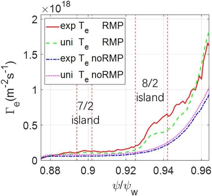
Plasma Sci. Technol. 23 (2021) 105104 J Fu et al
Figure 8. (a) Equilibrium electric field Er profiles of DIII-D for #158103 discharge during ELMing and ELM suppression. (b) Dependence
of non-ambipolar particle flux DGe on electric field amplitude EN at q = 4 flux surface in simulations with uniform and experimental Er
profiles, using the uniform kn and Te profiles. (c) Profiles of Ge at steady state of neoclassical simulations with Er profiles during ELMing (blue
line) and ELM suppression (red line), and without RMP (yellow line), using experimental density and temperature profiles. (d) Dependence
of time rate of change of Er at q = 4 flux surface on RMP amplitude α from simulations without equilibrium Er and with equilibrium Er
during ELMing and ELM suppression. Error bar represents experimental value with 50% uncertainty range.
flux on the equilibrium electric field indicates that some Here, the subscript s denotes the particle species (i for ion
electron orbits become stochastic due to the RMP. and e for electron). The flux-surface-averaged polarization
current on the left hand side cancels out with the guiding
center current on the right hand side. The relation between
¶f
Ey º - ¶y and radial electric field Er is Er = Ey∣ y ∣. The Gi
5. Rotation damping rate due to non-ambipolar and Ge are assumed to be ambipolar without the effects of
particle flux
RMP. For the non-ambipolar particle fluxes, only the electron
contribution is taken into account by assuming that the ion
In this section, we calculate the damping rate of the toroidal
contribution is negligible. Equation (4) is then used to cal-
rotation by calculating the time rate of change of the electric
culate the damping rate of the toroidal rotation.
field Er using the non-ambipolar particle flux DGe measured
Figure 8(d) shows the damping rate at the q = 4 flux sur-
in the steady state of the neoclassical simulations in the pre- face calculated from the simulations using the experimental n e , Te
vious sections. Combining the gyrokinetic Poisson’s equation and the two experimental Er profiles plotted in figure 8(a). When
and guiding center continuity equation, the quasi-neutrality comparing simulation results with the experimental measurement
condition takes the form [50], of the damping rate during the ELM suppression, two aspects of
uncertainty should be considered. The first one comes from the
dEy ∣ y ∣2 1 MHD simulations of the RMP amplitude α. In the α amplitude
=-
dt B2 m i n i c2 scanning, the damping rate is about one third of the experimental
level when a = a0 , but reaches the experimental level when
dB
´ å qs
s
ò d3v fs ⎛⎝vd + vE + v B0 ⎞⎠ · y
⎜ ⎟ . (4 ) using a = 2a0. The second uncertainty comes from the rapid
change of the Er during the transition from ELMing to ELM
9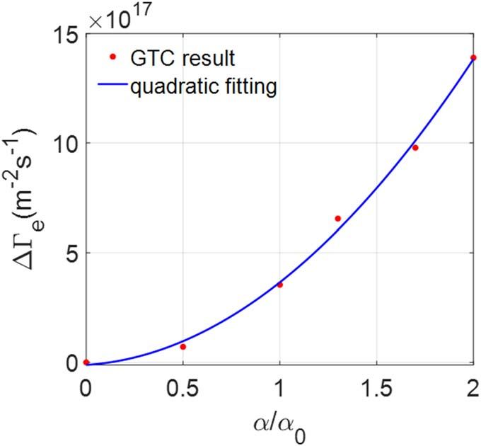
Plasma Sci. Technol. 23 (2021) 105104 J Fu et al
suppression. The damping rate is proportional to the non-ambi- flows on the q = 4 surface using the VMEC equilibrium with
polar particle fluxes DGe , which depends on the Er amplitude and various RMP amplitudes (without RMP, or amplified by 1, 2,
shear, as shown in figure 8(b). From the ELMing and ELM 5, 10 times) are shown in the figure 9(a). We can see that the
suppression state, the damping rate decreases drastically due to radial electric field evolves with a finite frequency, i.e.
the change of the equilibrium electric fields. This result is con- damped GAM oscillation, and then reaches a steady state. In
sistent with the experiment, in which the toroidal rotation the simulation without the RMP, the zonal flow residual level
experiences a large torque before the onset of the ELM sup- is very close to that in the simulation only with the adiabatic
pression, followed by relatively small torque after the transition to electrons, which indicates that the effect of the kinetic elec-
the ELM suppression state. The simulated damping rate during trons in zonal flow damping could be neglected without the
the ELM suppression qualitatively agrees with the experimental RMP. The zonal flow residual level is much higher than the
value. Rosenbluth–Hinton theory [53], which neglects shaping
effect and finite aspect ratio.
In the simulations with different RMP amplitudes, the
6. Effects of RMP on collisionless damping of change of the residual flow DEr is defined as the difference
zonal flows between the Er and that in the simulation without the RMP at
the same simulation time. The DEr is found to depend
To understand the RMP effects on zonal flow dynamics, quadratically on the RMP amplitude, which is consistent with
collisionless zonal flow damping and GAM are simulated by that in the section 3.3. As shown in the figure 9(b), when the
using two types of the 3D RMP fields. Besides the RMP RMP amplitude is amplified by 10 times, the change of the
equilibrium described above, another equilibrium is obtained residual flow DEr at t = 50R0 /cs could reach 60%, which is
from the ideal MHD code VMEC [29, 51], which includes three times larger than that in the simulation with only the
only the non-resonant response of the RMP and thus pre- adiabatic electrons. Here, the R0 is the major radius at
serves the closed flux surfaces. For the VMEC equilibrium, an magnetic axis, cs = Te /m i is the speed of ion acous-
electrostatic version of the fluid-kinetic hybrid electron model tic wave.
[52] is used to treat the kinetic electrons. In this model, the Figures 9(c) and (d) show the time history of radial
perturbed electron distribution function is represented by particle fluxes for the ion Gi and electron Ge in simulations
dfe = dfe(0) + dh e , where dfe(0) is the adiabatic response to the without RMP and RMP×10. The Gi oscillates with the
non-zonal electric field, and dh e is the nonadiabatic response. GAM frequency before t = 10R0 /cs. Subsequently, the Gi
For the M3D-C1 equilibrium with magnetic islands, the drift gradually drops to a much lower level in both the simulations.
kinetic equation DKE [40] is used for solving the electron On the other hand, the Ge has a strong oscillation with the
perturbed distribution function. Both the zonal and nonzonal GAM frequency before t = 10R0 /cs, which is mainly due to
electric field components are solved together in the presence electrons adiabatic response to the non-zonal electric fields
of magnetic islands. The ion dynamics is simulated by solving (m ¹ 0, n = 0 ), through the product of dfe(0) with vd. The Ge
the standard gyrokinetic equation. The radial particle flux in stays at a high level during t = (10 - 35) R0 /cs in the
this section is defined as simulation with RMP×10, but is always very small after
t = 12R0 /cs in the simulation without the RMP. This indi-
Gs = ò d3v dfs (vd + vE) · y , (s = i, e) cates that electron orbits could become stochastic due to the
large RMP amplitude, and the residual flow damping is
for the ions and electrons in the hybrid model using the mainly induced by electrons, rather than ions. This result may
VMEC equilibrium, and have implications on zonal flow dynamics in the tokamaks
dB with ripple fields and in the stellarators.
Gs = ò d3v d fs ⎛⎝vd + vE + v B0 ⎞⎠ · y
⎜ ⎟ , (s = i, e) Finally, to study the effects of the RMP islands on zonal
flow damping, the M3D-C1 equilibrium is used. The time
for the ions and the electrons in the DKE model using the evolutions of the radial electric field Er of the zonal flows
M3D-C1 equilibrium. with various RMP amplitudes (without RMP, with RMP and
In these simulations, a flux-surface-averaged ion guiding RMP×2) are shown in the figure 10(a). In the simulation
center density perturbation is initiated to generate the zonal without the RMP, the residual zonal flow is close to the result
flows. The radial profile of the zonal flows is set to be a sin- of the VMEC equilibrium within a difference of 20%, which
function with a radial wavevector kr ri = 0.4. The density could be due to the differences in the equilibrium and simu-
perturbation is set to be zero at the inner and outer boundaries lation model. The GAM oscillation (during (0–5)R0 /cs) is
of the simulation domain y = [0.90, 0.97] yw. Simulations in strongly damped when the RMP amplitude increases. The
this section use uniform equilibrium density and temperature residual flow in the simulation with the RMP×2 amplitude
profiles for both ions and electrons (Ti » 1.7Te ), corresp- with the magnetic islands has a 30% reduction, which is much
onding to the local parameters at the q = 4 surface of the larger than that in the simulation using the VMEC equilibrium
DIII-D experiment. without magnetic islands.
Firstly, we study effects of kinetic electrons by using Figure 10(b) shows the ion and electron particle fluxes in
gyrokinetic ions and fluid-kinetic hybrid electron model [52]. simulations without RMP and with RMP×2 using the M3D-
The time evolution of the radial electric field Er of the zonal C1 equilibrium with magnetic islands. In the simulation
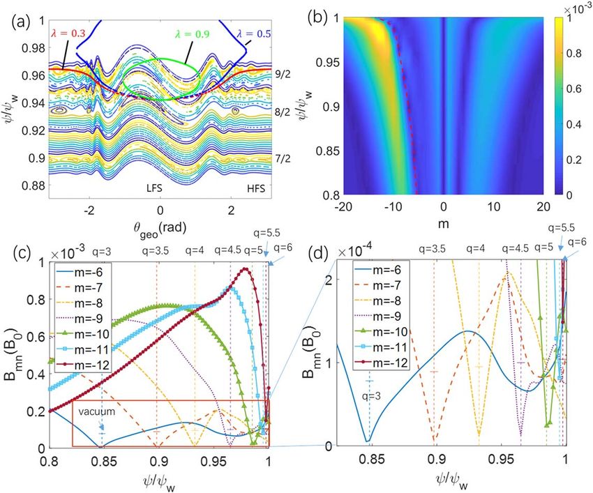
10Plasma Sci. Technol. 23 (2021) 105104 J Fu et al Figure 9. In simulations using VMEC equilibrium with closed flux surfaces, time evolutions of radial electric field Er of zonal flow with kinetic electrons with various RMP amplitudes (panel a), (b) relation between change of residual flow DEr at t = 50 R0 /cs and RMP amplitude α, radial particle flux (arbitrary unit) of ion Gi (panel c) and electron Ge (panel d) during zonal flow damping process without RMP (dashed lines) and with RMP×10 (solid lines). Er is normalized with initial value, DEr is normalized with residual flow without RMP, and particle flux is normalized with value of Ge at t = 10R0 /cs in simulation with RMP×10. without the RMP, the electron particle flux Ge oscillation is ambipolar electron particle fluxes, which lead to a rapid strong during the GAM oscillation. In the simulation with change of equilibrium radial electric field, consistent with the RMP×2, the electron particle flux Ge changes strongly at the experimental observations during the transition from ELMing early time (
Plasma Sci. Technol. 23 (2021) 105104                                                                                               J Fu et al

                                                                            China National Magnetic Confinement Fusion Science Pro-
                                                                            gram (Nos. 2017YFE0301300 and 2018YFE0304100); by the
                                                                            US Department of Energy (DOE) grant DE-SC0020413 and
                                                                            SciDAC ISEP Center, and by Princeton Plasma Physics
                                                                            Laboratory under Contract DE-AC02-09CH11466. This work
                                                                            used the resources of the Oak Ridge Leadership Computing
                                                                            Facility at the Oak Ridge National Laboratory (DOE Contract
                                                                            No. DE-AC05-00OR22725) and the National Energy
                                                                            Research Scientific Computing Center (DOE Contract No.
                                                                            DE-AC02-05CH11231). The work used data from the DIII-D
                                                                            National Fusion Facility, a DOE Office of Science user
                                                                            facility, under Awards DE-FC02-04ER54698. DIII-D data
                                                                            shown in this paper can be obtained in digital format by
                                                                            following the links at https://fusion.gat.com/global/
                                                                            D3D_DMP.
                                                                                 This paper was prepared as an account of work sponsored
                                                                            by an agency of the United States Government. Neither the
                                                                            United States Government nor any agency thereof, nor any of
                                                                            their employees, makes any warranty, express or implied, or
                                                                            assumes any legal liability or responsibility for the accuracy,
                                                                            completeness, or usefulness of any information, apparatus,
                                                                            product, or process disclosed, or represents that its use would
                                                                            not infringe privately owned rights. Reference herein to any
                                                                            specific commercial product, process, or service by trade name,
                                                                            trademark, manufacturer, or otherwise does not necessarily
                                                                            constitute or imply its endorsement, recommendation, or favor-
                                                                            ing by the United States Government or any agency thereof. The
                                                                            views and opinions of authors expressed herein do not neces-
                                                                            sarily state or reflect those of the United States Government or
                                                                            any agency thereof.

                                                                            ORCID iDs

                                                                            Jingyuan FU (付敬原)           https://orcid.org/0000-0002-
Figure 10. Time evolutions of radial electric field Er of zonal flows         8225-4156
(panel a), ion and electron radial particle fluxes (panel b), with
various RMP amplitudes in simulations using M3D-C1 equilibrium
including magnetic islands. Er is normalized with initial value,
particle fluxes are normalized with maximal value of ion particle flux        References
Gi in simulation without RMP.
                                                                             [1]   Kamiya K et al 2007 Plasma Phys. Control. Fusion 49 S43
                                                                             [2]   Lang P T et al 2013 Nucl. Fusion 53 043004
strongly screened magnetic perturbation because of a weaker                  [3]   Evans T E et al 2006 Nat. Phys. 2 419
Er shear induced by the non-ambipolar neoclassical transport                 [4]   Wade M R et al 2015 Nucl. Fusion 55 023002
(see the figure 7 in [31]).                                                   [5]   Unterberg E A et al 2010 Nucl. Fusion 50 034011
                                                                             [6]   Liang Y et al 2007 Phys. Rev. Lett. 98 265004
     In future simulations, we will couple tokamak core with                 [7]   Suttrop W et al 2011 Phys. Rev. Lett. 106 225004
SOL including magnetic separatrix, which could incorporate                   [8]   Jeon Y M et al 2012 Phys. Rev. Lett. 109 035004
ion orbit loss near the separatrix. We will also develop the                 [9]   Paz-Soldan C et al 2015 Phys. Rev. Lett. 114 105001
coupled neoclassical and turbulence simulations. Further-                   [10]   Nazikian R et al 2015 Phys. Rev. Lett. 114 105002
more, the transport of RMP-induced energetic particles will                 [11]   Taimourzadeh S et al 2019 Nucl. Fusion 59 046005
                                                                            [12]   Fitzpatrick R 1993 Nucl. Fusion 33 1049
also be studied by GTC.                                                     [13]   Shaing K C, Ida K and Sabbagh S A 2015 Nucl. Fusion 55
                                                                                      125001
                                                                            [14]   Liu Y Q, Kirk A and Nardon E 2010 Phys. Plasmas 17 122502
Acknowledgments                                                             [15]   Seol J and Shaing K C 2017 Phys. Plasmas 24 092515
                                                                            [16]   Zhu W et al 2006 Phys. Rev. Lett. 96 225002
                                                                            [17]   Sun Y et al 2012 Nucl. Fusion 52 083007
The authors would like to thank J Bao, L Shi and S Tai-                     [18]   Park J K et al 2013 Phys. Rev. Lett. 111 095002
mourzadeh for useful discussion, and acknowledge technical                  [19]   Logan N C et al 2016 Nucl. Fusion 56 036008
support by the GTC team. This work was supported by the                     [20]   Li X Y et al 2019 Phys. Plasmas 26 052512

                                                                       12
Plasma Sci. Technol. 23 (2021) 105104 J Fu et al
[21] Liu Y Q et al 2020 Nucl. Fusion 60 036018 [41] Fang K S, Bao J and Lin Z H 2019 Plasma Sci. Technol. 21
[22] Park G et al 2010 Phys. Plasmas 17 102503 115102
[23] Kim K et al 2012 Phys. Plasmas 19 082503 [42] Ferraro N M 2012 Phys. Plasmas 19 056105
[24] Waltz R E and Waelbroeck F L 2012 Phys. Plasmas 19 032508 [43] Xiao Y et al 2015 Phys. Plasmas 22 022516
[25] Kwon J M et al 2018 Phys. Plasmas 25 052506 [44] Joseph I 2012 Contrib. Plasma Phys. 52 326
[26] Heyn M F et al 2014 Nucl. Fusion 54 064005 [45] Kanno R et al 2016 Contrib. Plasma Phys. 56 592
[27] Park J K et al 2009 Phys. Plasmas 16 056115 [46] White R B and Chance M S 1984 Phys. Fluids 27 2455
[28] Lin Z et al 1998 Science 281 1835 [47] Lin Z, Tan W M and Lee W W 1995 Phys. Plasmas 2
[29] Holod I et al 2016 Nucl. Fusion 57 016005 2975
[30] Hager R et al 2019 Nucl. Fusion 59 126009 [48] Hinton F L and Hazeltine R D 1976 Rev. Mod. Phys. 48 239
[31] Hager R et al 2020 Phys. Plasmas 27 062301 [49] Cole A J, Hegna C C and Callen J D 2007 Phys. Rev. Lett. 99
[32] Rechester A B and Rosenbluth M N 1979 Phys. Rev. Lett. 065001
40 38 [50] Wang W X, Hinton F L and Wong S K 2001 Phys. Rev. Lett.
[33] Leconte M and Diamond P H 2012 Phys. Plasmas 19 055903 87 055002
[34] Terry P W et al 2013 Phys. Plasmas 20 112502 [51] Hirshman S P and Whitson J C 1983 Phys. Fluids 26 3553
[35] Choi G J and Hahm T S 2018 Nucl. Fusion 58 026001 [52] Lin Z et al 2007 Plasma Phys. Control. Fusion 49 B163
[36] Wang H Y et al 2020 Phys. Plasmas 27 082305 [53] Rosenbluth M N and Hinton F L 1998 Phys. Rev. Lett. 80 724
[37] Fu J Y et al 2021 Phys. Plasmas 28 062309 [54] Ghendrih P, Grosman A and Capes H 1996 Plasma Phys.
[38] Jiang P et al 2016 Plasma Sci. Technol. 18 126 Control. Fusion 38 1653
[39] Dong G and Lin Z 2016 Nucl. Fusion 57 036009 [55] Xu Y et al 2006 Phys. Rev. Lett. 97 165003
[40] Fang K S and Lin Z 2019 Phys. Plasmas 26 052510 [56] Tamain P et al 2010 Plasma Phys. Control. Fusion 52 075017
13You can also read