PHOTOGRAMMETRY AND COMPUTED TOMOGRAPHY POINT CLOUD REGISTRATION USING VIRTUAL CONTROL POINTS - The International Archives of the ...
←
→
Page content transcription
If your browser does not render page correctly, please read the page content below
The International Archives of the Photogrammetry, Remote Sensing and Spatial Information Sciences, Volume XLIII-B2-2021
                                                  XXIV ISPRS Congress (2021 edition)

               PHOTOGRAMMETRY AND COMPUTED TOMOGRAPHY POINT CLOUD
                     REGISTRATION USING VIRTUAL CONTROL POINTS

                                                     K. Zhan1, ∗, D. Fritsch2 , J.F. Wagner1
        1
            Chair of Adaptive Structures in Aerospace Engineering, University of Stuttgart - (kun.zhan, jfw)@pas.uni-stuttgart.de
                                     2
                                       Institute for Photogrammetry - dieter.fritsch@ifp.uni-stuttgart.de

KEY WORDS: Geometric Primitives, Plane Detection, Computed Tomography, RANSAC, Point Correspondence, Photogram-
metry.

ABSTRACT:

In this paper we propose a virtual control point based method for the registration of photogrammetry and computed tomography
(CT) data. Because of the fundamentally different two data sources, conventional registration methods, such as manual control
points registration or 3D local feature-based registration, are not suitable. The registration objective of our application is about
3D reconstructions of gyroscopes, which contain abundant geometric primitives to be fitted in the point clouds. In the first place,
photogrammetry and CT scanning are applied, respectively, for 3D reconstructions. Secondly, our workflow implements a seg-
mentation after obtaining the surface point cloud from the complete CT volumetric data. Then geometric primitives are fitted in
this point cloud benefitting from the less complex cluster segments. In the next step, intersection operations of the parametrized
primitives generates virtual points, which are utilized as control points for the transformation parameters estimation. A random
sample consensus (RANSAC) method is applied to find the correspondences of both virtual control point sets using corresponding
descriptors and calculates the transformation matrix as an initial alignment for further refining the registration. The workflow is
invariant to pose, resolution, completeness and noise within our validation process.

                        1. INTRODUCTION                                   mal aligned radial feature (NARF) (Rusu and Cousins, 2011)
                                                                          etc. have problems in the computation efficiency and even in
Sensor fusion is an important topic in many fields, because in            detecting validate feature correspondences. These problems
real applications it is quite often difficult for a single sensor         occur due to the original discrepancy between photogrammetry
alone to provide the complete desired information. Therefore,             and CT data, such as density, edge and material characteristics,
the advantages of different sensors are integrated to strengthen          and the incomplete representation of CT scans.
the data characteristics. In the 3D digitization field of Tech            There are also works using geometric primitives such as
Heritage (TH), the Gyrolog project (Fritsch et al., 2018;                 (Alshawa, 2007) applies lines instead of points to implement
Fritsch et al., 2021) funded by the Federal Ministry of Edu-              an iterative process. But the application is intended to solve
cation and Research of Germany, has innovatively introduced               the registration of topographic terrestrial laser scanner data.
different methodologies, such as Photogrammetry, Computed                 (Yang et al., 2016) introduced a registration method based on
Tomography (CT) as well as Endoscopy for the 3D digitization              semantic feature points, which also rely on the line feature
of the gyroscopic instrument collection of the University of              and works for terrestrial laser scanning data. (Stamos and Le-
Stuttgart. The combination of photogrammetry and CT has                   ordeanu, 2003) calculates the intersection lines of neighboring
been discussed frequently in the medical field (Bolandzadeh               planes and estimate the transformation matrix with at least two
et al., 2013), however, has not yet been applied often in TH              corresponding line pairs. (Theiler et al., 2012) put forward
digitization applications (Zhan et al., 2020). This paper mainly          a terrestrial point clouds registration method by using virtual
discusses a new registration method of photogrammetric and                tie points from the intersection of plannar surfaces. However,
CT point clouds in such TH applications, where complete                   the method deals with point clouds from the same source and
models are required.                                                      a relatively easier situation for planes extraction. All the listed
A point cloud is chosen as the common representation for                  works are generally to align the point clouds based on primitive
photogrammetric surface data and CT volumetric data, due to               based information, they are more focusing on the same data
the fact, that point cloud registration is an ongoing topic in the        type with same characteristics and lack the adaptability for
field of photogrammetry and computer vision, with various                 multi-source data as well as complex structured 3D models.
methods being put forward. The most frequently applied                    Other possibilities such as the artificial landmarks (Ayoub et
method is the iterative closest point (ICP) registration (Besl            al., 2007; Xin et al., 2013), however, have various drawbacks:
and McKay, 1992) or it’s variants, which iteratively calculates           (a) CT data contains no texture information, only geometry
the discrepancy of the overlap between two point clouds.                  information could be used; (b) some of the surface information
Despite the wide application and continuous research with                 will be incomplete due to the characteristics of the CT scan; (c)
many algorithm variants, the requirement of sufficient initial            unsharpness of corners for photogrammetry data which limits
registration makes it only suitable for the refinement of the             the accuracy of the manual control point picking process.
registration.
Methods based on automatic 3D features extraction such as the
                                                                          The proposed method below takes advantages of the char-
fast point feature histogram (FPFH) (Rusu et al., 2009) or nor-
                                                                          acteristic of the artificial objects containing many regular
∗   Corresponding author                                                  geometry shapes such as cylinders, spheres or simply planes.

                                                    This contribution has been peer-reviewed.
                     https://doi.org/10.5194/isprs-archives-XLIII-B2-2021-265-2021 | © Author(s) 2021. CC BY 4.0 License.                265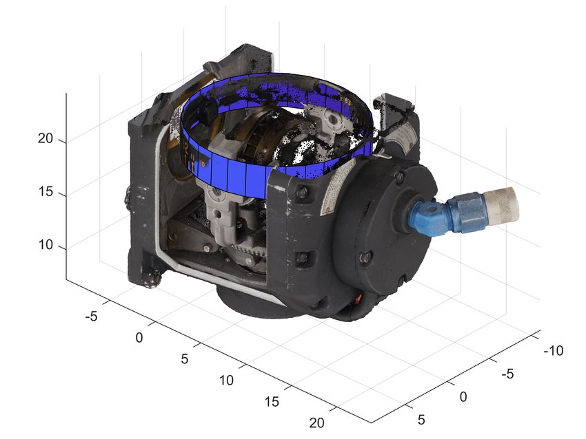
The International Archives of the Photogrammetry, Remote Sensing and Spatial Information Sciences, Volume XLIII-B2-2021
                                                 XXIV ISPRS Congress (2021 edition)

For a best-fit process, point cloud segmentation is necessary         2.2   Primitive fitting
to increase both the efficiency and precision. In our case, the
region growing method (Vo et al., 2015) using just the normal         The preliminary step of primitive fitting is point cloud segment-
and other attributes such as the color, delivers good results.        ation, which has not been mentioned in most other point cloud
Most frequent geometric primitives, such as planes, are fitted        registration methods using geometric primitives. However, for
and used for control point determination by intersections. In         a watertight 3D model of a complex structured gyroscope ob-
addition, the primitives such as spheres or 3D circles could          ject, the fitting process will be influenced by the spatial dis-
directly provide their centre points as control points. The           tribution of the points. Therefore, it is of vital importance to
correspondence of the extracted control point information from        implement the point cloud segmentation into different clusters
both datasets could be estimated via the RANSAC method                before fitting the primitives. Region growing is a conventional
(Buch et al., 2013). Afterwards, the registration is refined,         segmentation method, which is also validated in this work. A
based on the initial virtual control points selection.                CT point cloud has high geometric accuracy regarding the voxel
                                                                      positions as well as the normals. Therefore, a region growing
                                                                      algorithm using the normals and curvatures works well in CT
                                                                      surface point cloud segmentation. As for photogrammetry, the
                         2. METHOD                                    primitives generally differ from each other in material and color.
                                                                      Hence the color-based region growing segmentation is applied
In the proposed workflow as shown in Figure 1, point clouds           for the photogrammetric 3D model.
from CT and photogrammetry are generated from the multiple            For each segmented cluster, parameterized geometric primitives
CT slices and multi-view imagery, respectively. After obtain-         are used to fit to the discrete point cloud data. Like other fitting
ing a CT surface point cloud, we implement the segmentation           problems, various principles are available but mostly origin-
for the purpose of fitting geometry primitives for both datasets.     ates from RANSAC. Due to the diversity of the point clouds,
The segmentation applies region growing methods based on dif-         a simple threshold definition is hardly to meet the requirements
ferent principles, such as color information, curvatures etc. In      for a best primitive fitting problem. Maximum Likelihood Con-
the next step, the virtual control points are calculated to estim-    sensus (MLESAC), which improves the RANSAC by optim-
ate the transformation matrix with an refinement as a follow-up.      izing the inlier scoring rather than simply counting the inlier
                                                                      numbers, is adopted. The coefficients of the most frequent 3D
                                                                      primitives are listed as Table 1.

                                                                      3D Primitives    Point      Vector Constant   Angle
                                                                          Cone         Apex        Axis           Open angle
                                                                         Plane                    Normal Distance
                                                                         Sphere        Center             Radius
                                                                        Cylinder    Point on axis Axis    Radius
                                                                       3D Circle       Center     Normal Radius

                                                                                     Table 1. Coefficients of 3D primitives

  Figure 1. Virtual control points based registration workflow.       2.3   Correspondance Estimation

                                                                      With good fitting results, these parameterized primitives can be
                                                                      used to directly or indirectly obtain virtual control points. Be-
2.1   3D reconstruction                                               cause the fitting process is based on the RANSAC principle,
                                                                      the virtual control points are the representation of the overall
Generally 3D reconstruction is the technology of determining          characteristics of the point cloud clusters. Theoretically, they
the 3D digital representation of a real object. The principle of      are more reliable than the manually selected control points or
photogrammetry is to use the overlapping information between          the feature points calculated using the neighboring informa-
multiview images to solve the 2D to 3D projection, and finally        tion from the incomplete point cloud. After obtaining the vir-
obtain the 3D surface model with texture. The quality of the          tual control points, their corresponding relationship needs to be
final 3D model depends on factors such as the texture homo-           solved. In general, after obtaining the key points, the corres-
geneity of the object, the redundancy and the resolution of the       ponding descriptor will be calculated for the process of corres-
photos, which reflect on the accuracy or even the completeness        pondence estimation. Global and local descriptors use global
of the final 3D model. CT scanning records the attenuation in-        and neighborhood point information respectively, but these are
formation in each voxel space by X-rays passing through the           not applicable to calculate virtual points, due to the fact that
object to reflect the internal structure and material properties of   virtual points are outside the point cloud. The information of
the object. The final 3D CT volumetric model consists of voxels       geometric primitives, which is used for virtual control point
with penetrating information. Though having the ability to re-        calculation, could be encoded. The virtual control points could
cover the internal information in a non-destructive way, CT 3D        be obtained from the center of a sphere, the intersection of the
reconstruction suffers from the noise and beam hardening arte-        cylinder axis and the plane, or the intersection of three planes.
facts and scattering. More details of 3D reconstruction as well       (Theiler et al., 2012) applied mainly the plane angle for the con-
as the CT surface extraction process could be referred to (Zhan       dition of three planes intersection. If (a1 , b1 , c1 ) and (a2 , b2 , c2 )
et al., 2020).                                                        stand for normal vectors of two intersecting planes, the angle

                                                This contribution has been peer-reviewed.
                 https://doi.org/10.5194/isprs-archives-XLIII-B2-2021-265-2021 | © Author(s) 2021. CC BY 4.0 License.                       266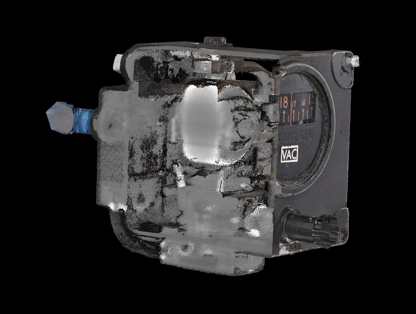
The International Archives of the Photogrammetry, Remote Sensing and Spatial Information Sciences, Volume XLIII-B2-2021
XXIV ISPRS Congress (2021 edition)
between can be expressed as (1), mathematical derivation could be referred to (Fritsch et al.,
2021).
a1 · a2 + b 1 · b 2 + c 1 · c 2
α = arccos p p (1)
a21 + b21 + c21 · a22 + b22 + c22
3. EXPERIMENT AND RESULTS
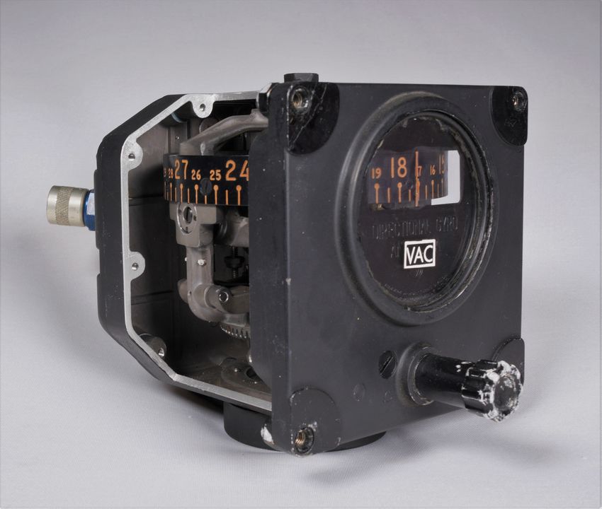
We denote planes that are related to the intersection point as 3.1 Object
target planes, which can be ordered by the angles, and the rest
non-target planes. Except the angles between target planes, the The main experimental object for this study is a pneumatically
angles between each target plane and all non-target planes could driven directional gyro, manufactured by GM corp in US as
also be calculated. All angle values are binned into a histogram. shown in Figure 3. The object is chosen due to its rich geo-
A similar to the idea of a point feature histogram (PFH), the bin- metric primitives design while few evident corner points within
ning process divides the angles into certain subdivisions, and the rounded edges could be manually picked for CT and photo-
counts the number of occurances in each subinterval. A sim- grammetry point cloud registration.
ilar process could also be applied to the cylinder axis and plane
intersection situation by replacing the plane angle to line-plane
angle. An example is shown in Figure 2.
Figure 3. Original image of the Ternstedt directional gyro
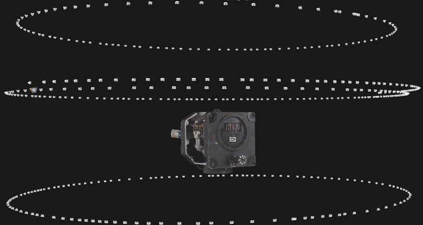
3.2 CT and photogrammetry 3D reconstruction
Figure 2. Histogram of plane angles.
The sensors used for CT scanning and photogrammetry can be
2.4 Error analysis referred to (Zhan et al., 2020). As for photogrammetric 3D
reconstructions, Figure 4 shows the camera poses represented
After the correspondence estimation, the transformation mat- by circular white rectangles via SfM (Structure-from-Motion)
rix can be directly calculated to serve as an initial match. The and the watertight 3D surface model from DIM (Dense Image
next method is generally through ICP. ICP is mainly an iterat- Matching) and texturing procedure.
ive loop to calculate the nearest neighbors of two sets of point
clouds, and usually good results can be obtained under good
initial matching conditions. In the iterative process, the sum of
the squared errors, as shown in (2) is minimized.
Np
1 X
E(R, t) = · kxi − R · pi − tk2 (2)
Np
i=1
where Np is the number of points, xi and pi are corrresponding
points, R and t are rotation and translation, respectively.
Though ICP is widely used, it is a well-known fact, that most
implementations of ICP do not consider precision measures as
given in the field of photogrammetry. The alternative could
Figure 4. Photogrammetric 3D surface model of Figure 3
be based on the least squares method. Here we use the well-
known Gauss-Helmert model to solve the overall 7 parameters
transformation problem as shown in (3). In addition, for CT is used to reconstruct internal structures of an object that is
providng a best fusion model, a complete accuracy evaluation not visible from outside. Figure 5(a) shows the complete CT
result using the law of error propagation can also be obtained reconstructed 3D model visualized in VGStudio (VGStudio,
with the assumption of precision values for both data sets, the n.d.). Figure 5(b) is the point cloud of CT data by representing
target and the source data. each voxel by the center point with its intensity value.
X = X0 + µ · R · x (3) 3.3 CT surface extraction
where X and x stand for target and source points, µ, X 0 and The CT volume can be converted to the point cloud according
R are scale, translation and rotation respectively. More detailed to the spatial coordinates of each voxel. The coordinate of each
This contribution has been peer-reviewed.
https://doi.org/10.5194/isprs-archives-XLIII-B2-2021-265-2021 | © Author(s) 2021. CC BY 4.0 License. 267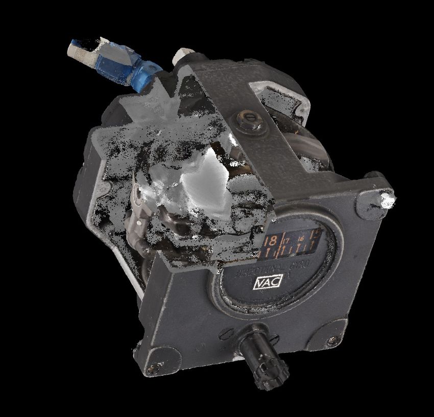
The International Archives of the Photogrammetry, Remote Sensing and Spatial Information Sciences, Volume XLIII-B2-2021
XXIV ISPRS Congress (2021 edition)
(a) 3D volumetric model (b) Point cloud (a) plane fitting (b) cylinder fitting
Figure 5. CT 3D model of Figure 3 Figure 7. Primitives fitting on photogrammetry model
voxel is calculated with the use of the grid origin of the reg- in Figure 8. For the differences between two data-sets as well
ular CT volume and grid spacing, which describes the initial as the primitive fitting procedures, the control points may be
position of the volume and space between two voxels respect- disordered and different in quantity. To determine the trans-
ively. Thereafter a CT surface extraction is necessary to provide formation, the control points together with their descriptors as
the similar information as given by the photogrammetric point introduced in 2.3 are to be estimated for corresponding point
cloud for registration. We apply a ball query method for each pairs.
point to extract the points with less neighbouring points within The obtained result is used for the transformation matrix cal-
a threshold range, which are interpreted as the points on the
surface of the 3D CT model. An alternative method finding the
convex hull could be found in (Zhan et al., 2020). Figure 6(a)
shows the surface extraction result. In addition, by removing
this shell of certain thickness will also avoid the visualization
ambiguity of the integrated model on the surface.
(a) Extracted surface (b) Segmentation result
Figure 8. Virtual control points of photogrammetric model
Figure 6. CT surface point cloud
3.4 Point cloud segmentation and primitive fitting culation as initial registration for the later refinement by ICP
and/or the Gauss-Helmert Model. With two transformation
After obtaining a CT surface and photogrammetric point matrices, the photogrammetry point cloud and the CT point
cloud, the implementation of a direct geometry primitive fitting cloud without the outer shell could be registered together. In our
may result in unsatisfying output, due to the highly complex experiment both refinement methods delivered good registra-
structure of our objects, which are gyroscopes. Therefore, a tion results without too much differences. Cross sections of the
point cloud segmentation as shown in Figure 6(b) using region photogrammetry and CT models are displayed in Figure 9. Ad-
growing methods based on different principles is necessary ditionally, more detailed precision measures could be obtained
beforehand, considering the differences of the sensors as well by the Gauss-Helmert Model estimation. The ground sampling
as the object structure characteristics. distances (GSD) of the photogrammetry and CT for our ap-
A well-segmented point cloud contributes to an easier and more plication are 0.05-0.09mm and 0.06mm respectively. With 25
precise best-fit of geometric primitives based on RANSAC. The corresponding joint control points, the estimated standard devi-
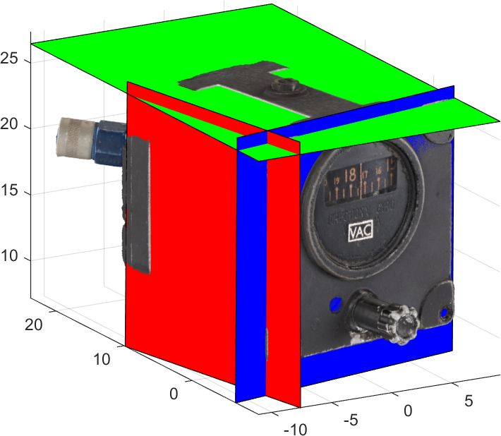
plane, as the most frequent geometric primitive in gyroscopes, ation of unit weight σ = 1.03, the estimated precision of CT
is determined by the inliers, i.e. extracted co-planar points with σCT = 0.07mm, and the estimated precision of photogram-
a predefined threshold. Figure 7 displays examples of plane metry is σphot = 0.06mm. On the one hand, a high precision
and cylinder fitting using the Point Cloud Library (PCL) (Rusu pose correspondence is realized between two data sources, and
and Cousins, 2011). A control point could be determined on the other hand the integrated model containing both a clean
by the intersection of every three non-parallel parameterized colored surface and internal structure information is derived.
planes with precise coordinates. In addition, other best-fit
primitives such as spheres or 3D circles could provide their 4. DISCUSSION AND CONCLUSION
center point directly as control points.
4.1 Summary the findings
3.5 Transformation matrix estimation The proposed workflow takes into consideration the character-
istics of the point clouds from different sensors for designing
In the next step, two sets of points are obtained as control points appropriate steps for a good registration. Due to the difference
for the estimation of the transformation parameters as shown of CT volumetric data from the normal surface point cloud, the
This contribution has been peer-reviewed.
https://doi.org/10.5194/isprs-archives-XLIII-B2-2021-265-2021 | © Author(s) 2021. CC BY 4.0 License. 268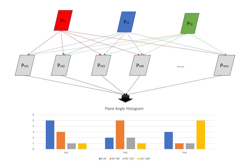
The International Archives of the Photogrammetry, Remote Sensing and Spatial Information Sciences, Volume XLIII-B2-2021
XXIV ISPRS Congress (2021 edition)
such as well-extracted CT surfaces, more robust point cloud
segmentations, more adaptive primitive fittings regarding dif-
ferent objects as well as a finding more efficient descriptors for
the virtual control points.
4.3 Outlook
With regard to the analysis in section 4.2, the automation of the
(b) Cross section 2
(a) Cross section 1 workflow of each single step is necessary and can be improved.
In addition, a more detailed comparison regarding other regis-
Figure 9. Cross sections of the integrated model tration strategies should be implemented to validate the pro-
posed method, for general application scenarios.
CT data is transformed into the point cloud format and the sur-
face extraction is implemented to be fitted into the point cloud ACKNOWLEDGEMENTS
registration framework. As for the common incomplete rep-
resentation of the surface of CT scanning data, virtual control The authors wish to thank the reviewers for their comments.
points generated by the fitted primitives rather than the local The authors also gratefully acknowledge the funding of this re-
information depending 3D features are applied for the trans- search within the Gyrolog project of the German Ministry of
formation estimation. Education and Research (BMBF), FKZ 01UG1774X. .
4.2 Strength and weakness analysis
REFERENCES
The proposed workflow has advantages in aspects (a) robust-
ness against the noise of the point cloud; (b) robustness against
Alshawa, M., 2007. lCL: Iterative closest line A novel point
incomplete CT data due the low penetration of some materials;
cloud registration algorithm based on linear features. Ekscentar,
(c) high efficiency on condition of good primitive fitting results.
53–59.
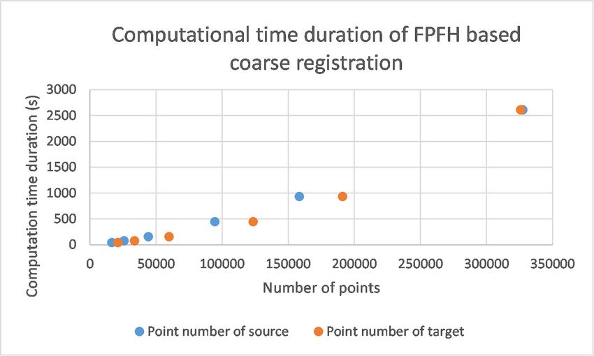
Except the proposed workflow, registrations with other prin-
ciples such as 3D feature-based and manual control point-based Ayoub, A., Xiao, Y., Khambay, B., Siebert, J., Hadley, D.,
registration are also under investigation. FPFH-based coarse 2007. Towards building a photo-realistic virtual human face for
registration suffers from the low efficiency. The relationship craniomaxillofacial diagnosis and treatment planning. Interna-
between the computing time and the number of points is plot- tional journal of oral and maxillofacial surgery, 36(5), 423–
ted and the registration is shown in Figure 10 and 11. Though 428.
the selection of manual control points works for coarse regis-
trations, it is very time consuming and delivers randomness in Besl, P. J., McKay, N. D., 1992. Method for registration of 3-d
the process, with unsharp corners of the photogrammetry data. shapes. Sensor fusion IV: control paradigms and data struc-
tures, 1611, International Society for Optics and Photonics,
586–606.
Bolandzadeh, N., Bischof, W., Flores-Mir, C., Boulanger, P.,
2013. Multimodal registration of three-dimensional maxillo-
dental cone beam CT and photogrammetry data over time. Den-
tomaxillofacial Radiology, 42(2), 22027087.
Buch, A. G., Kraft, D., Kamarainen, J.-K., Petersen, H. G.,
Krüger, N., 2013. Pose estimation using local structure-specific
shape and appearance context. 2013 IEEE International Con-
ference on Robotics and Automation, IEEE, 2080–2087.
Figure 10. FPFH-based coarse registration
Fritsch, D., Wagner, J. F., Ceranski, B., Simon, S., Niklaus, M.,
Zhan, K., Mammadov, G., 2021. Making Historical Gyroscopes
Alive—2D and 3D Preservations by Sensor Fusion and Open
Data Access. Sensors, 21(3). https://www.mdpi.com/1424-
8220/21/3/957.
Fritsch, D., Wagner, J. F., Simon, S., Ceranski, B., Niklaus, M.,
Zhan, K., Schweizer, T., Wang, Z., 2018. Gyrolog—towards vr
preservations of gyro instruments for historical and didactical
research. 2018 Pacific Neighborhood Consortium Annual Con-
ference and Joint Meetings (PNC), IEEE, 1–7.
Rusu, R. B., Blodow, N., Beetz, M., 2009. Fast point feature
histograms (fpfh) for 3d registration. 2009 IEEE international
Figure 11. FPFH-based computation time conference on robotics and automation, IEEE, 3212–3217.
Rusu, R. B., Cousins, S., 2011. 3d is here: Point cloud lib-
The proposed workflow involves several steps to reach the fi- rary (pcl). 2011 IEEE international conference on robotics and
nal registration. However, each single step could be improved, automation, IEEE, 1–4.
This contribution has been peer-reviewed.
https://doi.org/10.5194/isprs-archives-XLIII-B2-2021-265-2021 | © Author(s) 2021. CC BY 4.0 License. 269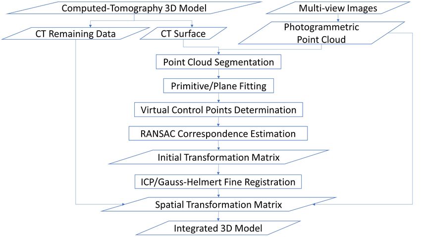
The International Archives of the Photogrammetry, Remote Sensing and Spatial Information Sciences, Volume XLIII-B2-2021
                                                XXIV ISPRS Congress (2021 edition)

Stamos, I., Leordeanu, M., 2003. Automated feature-based
range registration of urban scenes of large scale. 2003 IEEE
Computer Society Conference on Computer Vision and Pattern
Recognition, 2003. Proceedings., 2, IEEE, II–Ii.

Theiler, P., Schindler, K. et al., 2012. Automatic registration of
terrestrial laser scanner point clouds using natural planar sur-
faces. ISPRS Annals of Photogrammetry, Remote Sensing and
Spatial Information Sciences, 3, 173–178.

VGStudio, M., n.d. 3.3.6, volume graphics gmbh, d-69123
heidelberg, germany, 2020.

Vo, A.-V., Truong-Hong, L., Laefer, D. F., Bertolotto, M., 2015.
Octree-based region growing for point cloud segmentation. IS-
PRS Journal of Photogrammetry and Remote Sensing, 104, 88–
100.

Xin, P., Yu, H., Cheng, H., Shen, S., Shen, S. G., 2013. Im-
age fusion in craniofacial virtual reality modeling based on CT
and 3dMD photogrammetry. Journal of Craniofacial Surgery,
24(5), 1573–1576.

Yang, B., Dong, Z., Liang, F., Liu, Y., 2016. Automatic registra-
tion of large-scale urban scene point clouds based on semantic
feature points. ISPRS Journal of Photogrammetry and Remote
Sensing, 113, 43–58.

Zhan, K., Song, Y., Fritsch, D., Mammadov, G., Wagner, J.,
2020. Computed tomography data colouring based on photo-
grammetric images. ISPRS-International Archives of the Photo-
grammetry, Remote Sensing and Spatial Information Sciences,
43(B2), 361–368.

                                                This contribution has been peer-reviewed.
                 https://doi.org/10.5194/isprs-archives-XLIII-B2-2021-265-2021 | © Author(s) 2021. CC BY 4.0 License.          270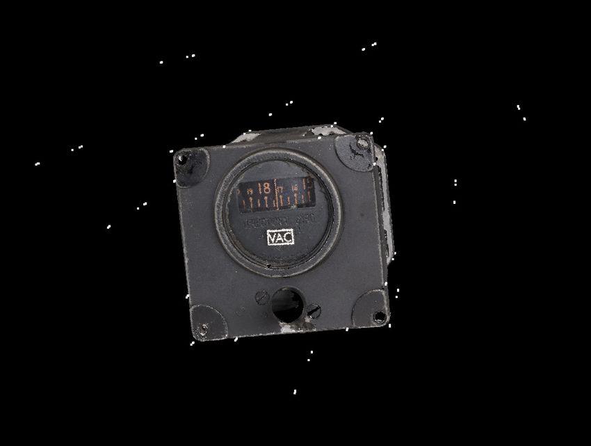
You can also read