| www.contemporaryresearch.com - Contemporary Research
←
→
Page content transcription
If your browser does not render page correctly, please read the page content below
972.931.2728 | 888.972.2728 | www.contemporaryresearch.com
Overview

The ICE-HE-DXL Display Control Center is an intelligent solution for “over-the-coax” RF display control to any combination of ICC1-
IRX Controllers, ICC1-232 Controllers, and ICC2-ATSC4S Tuner/Controllers. Control commands are sent over RF by inserting a micro
data channel in the gap between channels 4 and 5. In addition, its flexibility allows it to communicate with individual displays,
groups, zones, or all displays using any one of three software options: the onboard DX Lite web page, Display Express Software
from Contemporary Research, or third-party control systems.

DX Lite Web Page

The DX Lite web page can be configured to control up to 128 TVs, 24 channels, and 16 groups. No additional software is required,
and the entire system can be controlled from any web-enabled device such as a smartphone or tablet.

Display Express Software

By purchasing the additional Display Express Software which resides on a PC, the Display Control Center can be expanded to sup-
port up to 4000 TVs and 256 channels. The software offers increased flexibility by providing the ability to define presets, perform
advanced scheduling, configure multiple user levels, zones, etc.

Note: DX Lite does not convert to Display Express. The user must reconfigure the complete system with the new software. If using
Display Express Software, please refer to the “Display Express Software Manual” for detailed instructions.

Custom Control Systems

Custom control systems can connect to the Display Control Center through RS-232, front or rear panel USB, or Telnet, sending com-
mands via the published Contemporary Research ICC-Net protocol, controlling all TVs through a single control port.

Front-panel menus and the USB Service port simplify setup and firmware updates. In addition, a Display Express PC or other exter-
nal control system may be connected via the Ethernet, RS-232, or USB port on the back panel.

Note: The RS-232, front USB, and rear USB ports all perform the same function, but the front USB port is faster for firmware up-
dates.

      Page 2
                                                                                                      ICE-HE-DXL User Manual 04/2018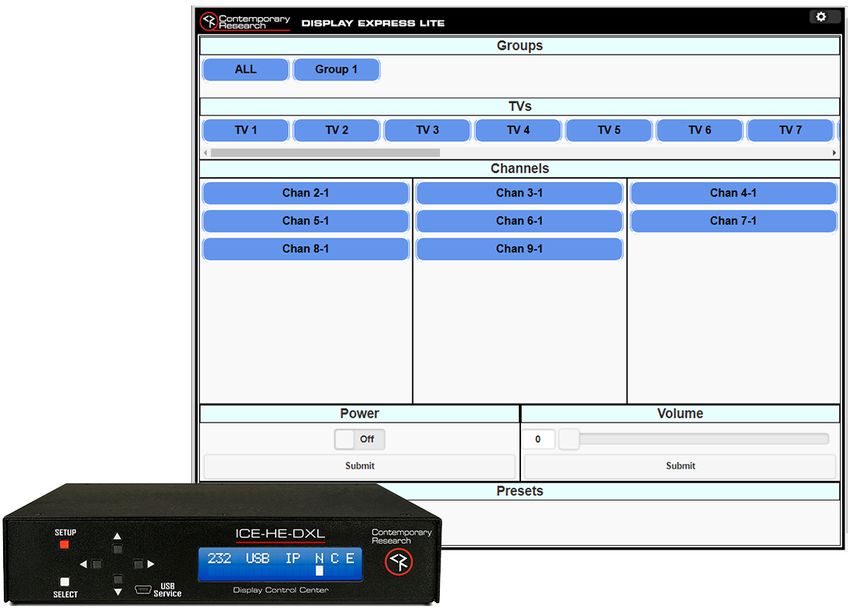
Specifications

Physical

Size: 8.5” [216mm] wide x 1.73” [44mm] high (1RU) x 6” [152mm] deep

Weight: 1.38 lbs. [628g]

Enclosure: Aluminum with durable black powder coat paint

Mounting: Mounts in included RKU 19” rack mount kit

Front Panel

Display: Text Display, white text on blue LCD

Control Buttons: SETUP, SELECT, and Up/Down/Left/Right arrows

Mini-B USB Port

Rear Panel

Control Connections – Ports can operate simultaneously.

Ethernet: 10/100BASE-T RJ-45 jack

RS-232: DB9 female, RS-232 data link

        2 – Rx

        3 – Tx

        5 – GND

USB: Mini-B USB Port

I/O 1 & 2: 6-pin captive screw terminal

        1 – PWR+        Power, 12 VDC, 250 mA max (using the included 500 mA power supply)

        2 – OUT2        Output 2

        3 – OUT1        Output 1

        4 – IN2		       Input 2

        5 – IN1		       Input 1

        6 – GND-        Ground

     Page 3
                                                                                             ICE-HE-DXL User Manual 04/2018
Both the front and rear panel USB ports and the RS-232 port all perform the functions of control and firmware updates. However, the
front panel USB performs faster firmware updates.

iCC-Net Connections

RF In: 		       ’F’, female, 75 ohm impedance, RF and iCC-Net from CATV system

		              (Only for legacy 2-way applications)

Data Receive:   Carried over the same RF coax connection as TV channels

		              Return signal from system controllers

		              Sub-band, 5.6 MHz, narrow-band signal below standard sub-band channels

		              -15 to +35 dBmV signal level (0 to +15 dBmV nominal)

RF Out: 		              ‘F’, female, 75 ohm impedance, RF to CATV distribution to controllers

Data Transmit: Mid-band VHF, 74.7 MHz, narrow-band signal between channels 4 and 5

		±80 KHz max carrier deviation

		              +14 to +45 dBmV, adjustable from front panel

Power Connections

Power In: 2.1 mm coaxial jack (inside center conductor positive), 11 to 18 VDC, 12 VDC typical, 250 mA maximum

Includes

12 VDC Power Supply, 500 mA 110/220VAC, 60/50 Hz

Embedded DX Lite software

       Page 4
                                                                                                    ICE-HE-DXL User Manual 04/2018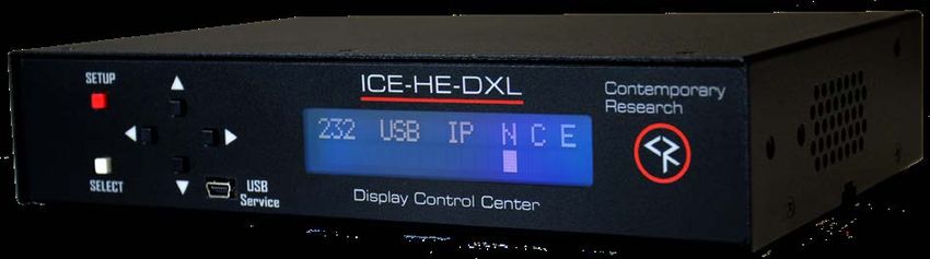
Installation

Remote Control Connection
There are three types of control ports:
    •    RS-232: Attach a null modem cable to the port. The default setting is 19.2K baud and can be changed via the front panel
         setup.
    •    USB: Connect a mini-B USB cable from a Display Express PC or other control system. It shows up as FT230X UART in Win-
         dows/Devices.
    •    Ethernet: Connect to an IP network port to access the internal DX Lite webpage, or use the port for telnet control or con-
         nection to a Display Express server.
RF Coax and iCC-Net Operation
    •    Connect an RF coax feed from RF Out to the system’s RF combiner, mixing the iCC-Net Out signal with the other CATV chan-
         nels. The iCC-Net Out channel operates at 74.7 MHz, between cable channels 4 and 5.
    •    When combining the RF output with QMOD modulators, the internal attenuator should be set to 29 dBmV to match the
         modulator’s level. 29 dBmV is the factory default setting.
    •    Do not connect any feeds to RF In in normal operation. It is used only for legacy 2-way applications.
AC Power
    •    Insert the DC power supply plug into the Power In jack.
    •    Plug the power adapter into an AC wall outlet. The front panel display should turn on.
I/O Port
    •    Inputs are 0-24 VDC or contact closure to ground. A closed contact closure creates a logical low; an open contact closure
         creates a logical high.
    •    Outputs are open collector and may require a pull-up resistor; 28 VDC max, 200 mA max. Turning on the output turns on
         the transistor and creates a current path to ground.

Simplified Output Circuit						Typical Application

        Page 5
                                                                                                      ICE-HE-DXL User Manual 04/2018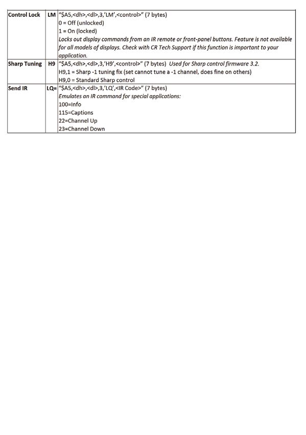
ICE-HE-DXL Setup

    Basic Network Setup
    •    Connect the Display Control Center to the network.

    •    Press the red SETUP button.

    •    Press the Down arrow until “Network” is displayed then press the white SELECT button.

    •    Use the Down arrow to view “IP Mode”.

    •    Use the Left or Right arrow to show “DHCP” then press the SELECT button to save the setting.

    •    To create a static IP address, choose “Static” mode and manually set an IP address. The unit will use the gateway settings it cap-
         tured in “DHCP”.

    •    Press SETUP then SELECT to show the IP Address.

    •    A PC’s Ethernet port may be directly connected to the ICE-HE-DXL’s Ethernet port. A cross-over cable is not required.

•       Enter the IP Address of the ICE-HE-DXL into the top entry bar on your browser.

•       The DX Lite home page will appear on your screen.

•       If the ICE-HE-DXL is connected to a network with Wi-Fi access, the unit may also be accessed from the browser on a tablet or
        smart phone.

          Page 6
                                                                                                              ICE-HE-DXL User Manual 4/2018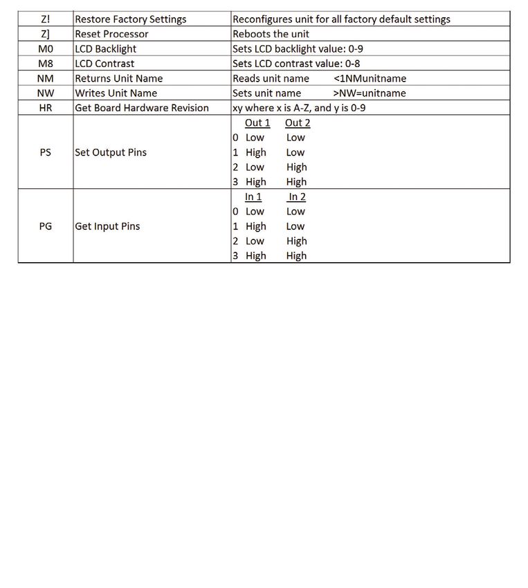
Front Panel Display

During normal operation, the ICE-HE-DXL displays the above text on the LCD display. The top line shows communication ports as
well as network and control status. “Rx” or “Tx” appears briefly under the three external ports (232, USB, IP) to show I/O activity,
and a white cursor will blink under the three status options (Network, Communication, Error).

•   232 – Active RS-232 port

•   USB – Active USB data port

•   IP – Active Ethernet port

•   N – ICC-Net status, blinking once per second, sending the “heartbeat” command to all TV controllers.

•   C – Valid ICC-Net command. The processor evaluates the syntax, and confirms when it is valid.

•   E – Error in ICC-Net control frequency. The unit auto-corrects the frequency, so you may see the error status briefly, such as
    when the unit is powered up. If the status stays constant, contact CR Support for service.

ICE-HE DXL Setup Menus
    Press the SETUP button to enter the menus. Use the Up/Down arrows to move through menus and the Left/Right arrows to
    change settings. Press SELECT to store the changes at each step.
             • Select a menu group (“System”, “Network”, “Command”) then SELECT to view that group’s menus.

             • Press SETUP to move back to other menu groups.

             • Pressing the Left/Right arrows together will reboot the unit.

    Page 7
                                                                                                       ICE-HE-DXL User Manual 04/2018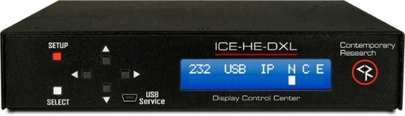
System            Factory Defaults are shown in Bold.
                  2400 | 4800 | 9600 | 19200 | 38400 | 115K This setting is for rear
   Baud Rate      USB and DB9.
  Pnl Lockout     None | Setup Press setup and right arrow key to temporarily unlock.
   Backlight      Display brightness 1-10 (9)
  LCD Contrst     Contrast 1-9 (5)
                  14-45 in 1 dB steps (29). Use 29 when combining with QMODs, 14
   RF Level dB    when connecting to QCA9-33 Low RF Input.
   Fact Dfault    Confirm: N | Confirm: Y Restores factory default settings.
                  Displayed as ICE-HE-DXL L/R arrows may be used to view boot-
   Firmware       loader and board rev.
Network
  IP Address      192.168.1.251
                  Static | DHCP Note: Changing IP address, gateway, & subnet are not
   IP Mode        permitted in DHCP Mode.
   Gateway        0.0.0.0
 Subnet Mask      255.255.255.0
    IP Port       23                    Telnet Port
   MAC/SN         00:14:C8:10:xx:xx
Command
    Power         All:On | All:Off
    Volume        All:Mute |All:Low | All:Medium
                  Zn: ALL,01-15 Un: ALL,001-255 Ty: 1-99(21)              Zone, Unit, Type
  Send IR Type    (IR Type)
                  Zn: ALL,01-15 Un: ALL,001-255 Ty: 1-99(21)              Zone, Unit, Type
  Send 232 Typ    (RS-232 Type)

Note: In the version of firmware available at this time, the “Send 232 Typ” command is supported only with the ICC2-ATSC 4S Tuner/
Controller. It is not yet functional with the ICC1-232 Controller.

 Send IR Type / Send 232 Typ Commands

In the Command section of the menu above, Send IR Type and Send 232 Typ are used to match the controllers to the specific TV
models and location on the network. There are three parts to the command, selected by moving the Left/Right arrows to each
value, then using the Up/Down arrows to set a number. Press SELECT to store the changes.

The following is a description of those commands.

All ICC-Net controllers have a display ID that is made up of two values: Zone and Unit. The displays are organized into 16 Zones of
255 displays each. The display number is equal to the Zone number plus the Unit number. For example: Display 258 is Unit 2 (2)
of Zone 1 (256).

      Page 8
                                                                                                      ICE-HE-DXL User Manual 04/2018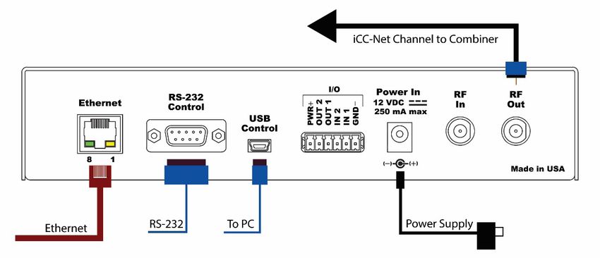
Zn:     Press the Right arrow to select the Zone, use the Up/Down arrow to select the Zone number.

        Zn = (0-15, or ALL). ALL TV Controllers will respond to a command sent to Zone ALL.
Un:     Press the Right arrow again to select a Unit number

        1-255 or ALL (all the controllers in that Zone)
Ty:     For a full list of IR codes, refer to the ICC1-IRX manual. Popular codes include:

        21=LG           44=Vizio

        25=Samsung      45=Panasonic

        43=Sony         46=Sharp

        For a full list of 232 codes, contact Contemporary Research Support. Popular codes include:

        54=LG          47 = Sharp

        11=Samsung 13=Panasonic
Se-     Press the white SELECT button to send the command
lect
Test    Use the Power command menu to test operation

       Page 9
                                                                                                      ICE-HE-DXL User Manual 04/2018
Display Express Lite

The Display Express Lite web page in the ICE-HE-DXL Display Control Center is a compact version of full Display Express software
that runs on a PC. The Lite version is focused on one task – tuning channels for a selected group of TVs, with the added options for
TV power and volume, and turning all the TVs on and off.

The page will scale to fit your screen, whether on a smartphone, tablet, or PC.

     Page 10
                                                                                                      ICE-HE-DXL User Manual 04/2018
Programming Display Express Lite
The first 20 TVs and 8 channels have been pre-
defined for ease of installation, but they may be
modified.
To customize the settings, click on the settings
icon at the top right and select “Toggle Edit Mode”
from the pop-up.
The page will change as shown, enabling the user
to edit Groups, TVs, and Channels. (Turn off the
edit mode when changes are complete.)
TVs
Display Express Lite supports up to 128 controlled
TVs in the system. When you choose to edit a TV,
you can do the following:
• Change the label to your preferred name.
• Assign a Group. Adding a new group num-
ber creates a new group.
• Change the address if needed.
Groups
Groups are created with the group number in the
TV buttons. The name of the group can be updat-
ed here.
Channels
Display Express Lite supports up to 24 channels.
Click on a channel button to change the name or
the channel number. Refer to the table below for
channel number conventions.
Channel Major # Minor #
Type
2-part
digital
1-part Leave
digital Blank
Analog 0
Page 11
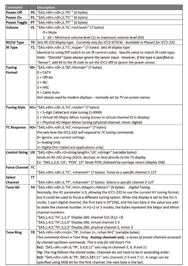
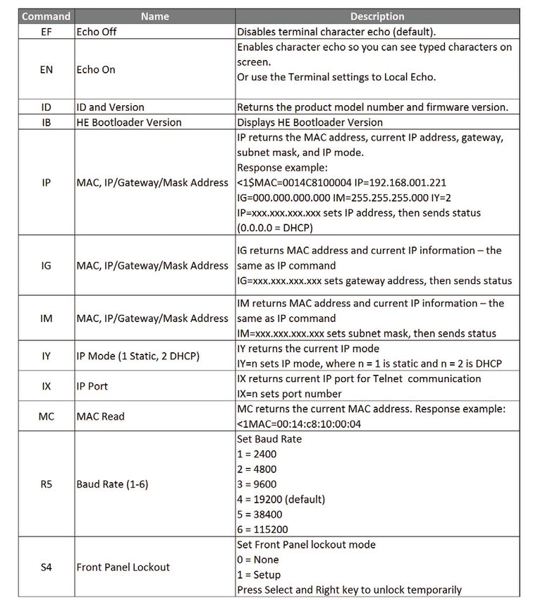
ICE-HE-DXL User Manual 04/2018RS-232 ICE-HE-DXL Commands
The following commands apply to the ICE-HE-DXL only. Commands addressed to controllers are included in the section for RS-232
Controller Commands.
All commands follow the same structure:
• Command strings begin with ASCII > (greater than symbol).
• Command strings end with a carriage return. ASCII CR, Hex 0D, or keyboard “Enter” are acceptable.
• Responses begin with ASCII < (less than symbol).
Example string: “>ID” will return “Page 13
ICE-HE-DXL User Manual 04/2018RS-232 Protocols for Custom Control Systems
Overview
RS-232 control for over 4000 TV Controllers is provided through an ICE-HE-DXL Display Control Center. The ICE-HE-DXL manages
ICC-Net communication over RF coax to ICC1-IRX and ICC1-232 Controllers as well as ICC2-ATSC 4S Tuner/Controllers.
Connection from the control system can be made through the RS-232 Control Port or Telnet. The default setting for the RS-232
Control Port is 19.2K baud, 8 data bits, no parity bit, and 1 stop bit. For testing purposes, a connection can be made through the
front or rear panel USB mini-B connector from a Windows PC. This connection will appear as a virtual COM port in Windows and
can be used with the IC Send software from Contemporary Research or a terminal emulation program.
Display Numbers
Each TV Controller is assigned a unique display number from 1 to 4094 to which control commands are addressed. The displays
are organized into 16 zones of 255 displays. All TV controllers in a zone will respond to a command sent to display 0. ALL TV con-
trollers will respond to a command sent to Zone 15, Display 255.
Zone Zone*256 Unit Display #
0 0 1-255 1-255
1 256 1-255 257-511
2 512 1-255 513-767
3 768 1-255 769-1023
4 1024 1-255 1025-1279
5 1280 1-255 1281-1535
6 1536 1-255 1537-1791
7 1792 1-255 1793-2047
8 2048 1-255 2049-2303
9 2304 1-255 2305-2559
10 2560 1-255 2561-2815
11 2816 1-255 2817-3071
12 3072 1-255 3073-3327
13 3328 1-255 3329-3583
14 3584 1-255 3585-3839
15 3840 1-254 3841-4094
All Zones 4095
Command String Structure
All commands follow the same structure:
• Attn - Hex A5
• Zone - 1-15 (Hex 01-0F)
• Unit - 1-255 (Hex 01-FF)
• Bytes - Number of bytes that follow
• Command - 1 byte
• Parameters - 1 to 4 bytes
Page 14
ICE-HE-DXL User Manual 04/2018Characters in command strings are expressed in a combination of hex and ASCII characters. For clarity, the following protocol
examples use the following conventions:
• Single-byte hex numbers are preceded by the ‘$’ symbol.
• ASCII characters or strings are enclosed in single quotes.
• Numbers not marked as hex or ASCII are a single decimal byte.
• Parameters shown in < > brackets are single byte.
• A series of multiple commands or parameters are set apart by [ ] brackets.
• Commas separate the bytes, but they are not part of the protocol.
• Double quotes enclose the command string, but they are not part of the protocol.
Command Format
“$A5,,,,,[]”
$A5 Starts the command
The zone or high order byte of the display
The unit or low order bye of the display (0 for global zone)
The number of command bytes to follow
The first command byte
Command parameters (not used in all commands)
[] Multiple commands can be concatenated, with byte count added to
String Format
Every software application has a different denotation for handling hex, ASCII, and decimal formats. The examples in this manual
are in AMX format, which is understood by many in the control industry.
• Hex values begin with a dollar ($) symbol.
• ASCII values are enclosed in single quotes.
• Decimal values are shown as normal.
If using a mixed-format structure for commands, convert the symbols to the types required by your software application. For
example, a Tune Channel 2-3 command to display 260 could be shown several ways:
• AMX Mixed Format = “$A5,1,4,5,’TH’,2,2,3”
• AMX Hex Format = “$A5 $01 $04 $05 $54 $48 $02 $02 $03”
• Standard Hex (no denotation) = A5 01 04 05 54 48 02 02 03
• Crestron Hex Format = \xA5\x01\x04\x05\x54\x48\x02\x02\x03
• RTI = Select port, hex mode, enter A5 01 04 05 54 48 02 02 03
Note: When returning to normal editing mode, the app inserts an \x before each hex character.
Go to www.asciitable.com for a handy Decimal/ASCII/Hex conversion chart.
Page 15
ICE-HE-DXL User Manual 04/2018RS-232 Controller Commands for ICC1-232, ICC1-IRX,
and ICC2-ATSC4s
Page 16
ICE-HE-DXL User Manual 04/2018Page 17
ICE-HE-DXL User Manual 04/2018Safety Instructions and Warranty
Read before operating equipment.
• Cleaning - Unplug this product from the wall outlet before cleaning. Do not use liquid cleaners or aerosol cleaners.
Use a damp cloth for cleaning.
• Power Sources - Use supplied or equivalent UL/CSA approved low voltage DC plug-in transformer.
• Outdoor Antenna Grounding - If you connect an outside antenna or cable system to the product, be sure the antenna
or cable system is grounded so as to provide some protection against voltage surges and built-up static charges. Section
810 of the National Electrical Code, ANSI/NFPA No. 70, provides information with respect to proper grounding of the
mast and supporting structure, grounding of the lead-in wire to an antenna discharge unit, size of grounding conduc-
tors, location of antenna discharge unit, connection to grounding electrodes, and requirements for the grounding
electrode.
• Lightning - Avoid installation or reconfiguration of wiring during lightning activity.
Power Lines - Do not locate an outside antenna system near overhead power lines or other electric light or power circuits or
where it can fall into such power lines or circuits. When installing an outside antenna system, refrain from touching such pow-
er lines or circuits, as contact with them might be fatal.
• Overloading - Do not overload wall outlets and extension cords as this can result in a risk of fire or electric shock.
• Object and Liquid Entry - Never push objects of any kind into this product through openings as they may touch danger-
ous voltage points or short out parts, resulting in a fire or electric shock. Never spill liquid of any kind on the product.
• Servicing - Do not attempt to service this product yourself as opening or removing covers may expose you to dangerous
voltage or other hazards. Refer all servicing to qualified service personnel.
• Damage Requiring Service - Unplug this product from the wall outlet and refer servicing to qualified service personnel
under the following conditions:
• When the power supply cord or plug is damaged.
• If liquid spills or objects fall into the product.
• If the product is exposed to rain or water.
• If the product does not operate normally by following the operating instructions. Adjust only those controls that are
covered by the operating instructions. An improper adjustment of other controls may result in damage and will often
require extensive work by a qualified technician to restore the product to its normal operation.
• If the video product is dropped or the cabinet is damaged.
• When the product exhibits a distinct change in performance, this indicates a need for service.
• Heat – This product should be situated away from heat sources such as radiators, heat registers, stoves, or other products
(including amplifiers) that produce heat.
* Note to CATV system installer: This reminder is provided to call CATV system installer’s attention to Article 820-40 of the
National Electrical Code (Section 54 of Canadian Electrical Code, Part I), that provides guidelines for proper grounding and,
in particular, specifies that the cable ground shall be connected to the grounding system of the building as close to the point
of cable entry as possible.
Page 18
ICE-HE-DXL User Manual 04/2018Warranty: Three (3) year limited warranty on all parts and labor for Contemporary Research manufactured products. Contem-
porary Research warrants its manufactured products against defects in materials and workmanship for a period of three years
from the day of purchase by authorized dealer. If Contemporary Research receives notice of such defects during the warranty
period; Contemporary Research, at its option, will repair or replace products that prove to be defective.
Exclusions: The above warranty shall not apply to defects resulting from improper or inadequate maintenance by the customer,
customers applied software or interfacing, unauthorized modifications or misuse, mishandling, operation outside the normal
environmental specifications for the product, use of the incorrect, modified or extended power supply, acts of God, weather,
or improper site operation and maintenance. Please note Contemporary Research SSV-DX Display Express PC product carries a
six-month limited warranty.
Product Service: Contemporary Research will test, repair, or replace the product or products without charge if the unit is un-
der warranty. If the product is out of warranty, Contemporary Research will test, and then repair the product or products. The
parts and labor charge will be estimated by a technician and confirmed by the customer prior to repair. All components must be
returned for testing as a complete unit. Contemporary Research will not accept responsibility for shipment after it has left the
premises.
Technical Support: Contemporary Research technicians will determine and discuss with the customer the criteria for repair
and/or replacement. Contemporary Research Technical Support can be contacted through one of the following resources:
e-mail support at support@crwww.com or phone at: 972-931-2728
Return Material Authorization (RMA) Number: Before returning a product for repair or replacement, request an RMA from
Contemporary Research’s technical support. Provide tech support with a return phone number, e-mail address, shipping address,
product serial numbers and original purchase order number. Describe the reason for repairs or returns as well as the date of pur-
chase. See the General RMA Terms and Procedures section for
more information. RMA’s are valid for 30 days and will be issued to authorized Contemporary Research dealers only. End users
must return products through authorized Contemporary Research dealers. Include the assigned RMA number in all correspon-
dence with Contemporary Research. Write the assigned RMA number clearly on the shipping label of the box when returning
the product. All products returned for credit are subject to a restocking charge without exception.
Voided Warranty: The warranty does not apply if the original serial number has been removed or if the product has been disas-
sembled or damaged through misuse, accident, acts of God, weather, modifications, use of incorrect, modified or extended power
supply, or unauthorized repair.
Shipping and Handling: Contemporary Research will not pay for inbound shipping transportation or insurance charges or accept
any responsibility for laws and ordinances from inbound transit. Contemporary Research will pay for outbound shipping, trans-
portation, and insurance charges for all items under warranty, but will not assume responsibility for loss and/or damage by the
outbound freight carrier. If the return shipment appears damaged, retain the original boxes and packing material for inspection by
the carrier. Contact your carrier immediately.
Products not under Warranty: Payment arrangements are required before outbound shipment for all out of warranty products.
General RMA Terms and Procedures: RMA’s are valid for 30 days and will be issued only to authorized active Contemporary Re-
search dealers and distributors.
• End users must return products through authorized Contemporary Research dealers. End users may be eligible for a RMA
at the discretion of CR Technical Support.
• Before a defective product can be authorized to send in for repair, it must first go through the troubleshooting process
with a member of the Contemporary Research Technical Support team.
• Products authorized for repair must have a valid RMA (Return Material Authorization) number.
• Contemporary Research Technical Support will approve the issue of an RMA number.
• An RMA number is to be included in all correspondence with Contemporary Research.
• The RMA number must appear clearly on the shipping label when the product is returned.
• A packing slip must be included on the inside of the box with the RMA number listed and reason for RMA return.
• Products received at Contemporary Research that do not have a valid RMA number clearly marked on the outside of
the shipping container may be refused and returned to sender.
• Boxes showing external damage will be refused and sent back to the sender regardless of the clearly marked RMA
number and will remain the responsibility of the sender.
Advanced Replacement Policies:
• For Contemporary Research manufactured products, advance replacement will be provided for “out-of-the-box” fail-
ures up to thirty (30) days after the initial shipment of products.
Shipments of equipment that are refused upon attempted delivery, for any reason, are subject to restocking charges.
Page 19
ICE-HE-DXL User Manual 04/2018You can also read