Scoot Control EN User & Installation Manual - Medema
←
→
Page content transcription
If your browser does not render page correctly, please read the page content below
User & Installation Manual

                                           EN
.

        Scoot Control
    Effortless attendant controller

         Scoot Control (P015-61) –R-net
Contact & Product

mo-Vis bvba

      Biebuyckstraat 15 D
      9850 Deinze - Belgium
      Website: www.mo-vis.com
      E-mail: contact@mo-vis.com
      Telephone: +32 9 335 28 60

Scoot Control User & Installation manual

      Produced and published by mo-Vis bvba, Belgium
      Edition 3, April 2020
      Manual item: D-P015-61-70-02
      Download the latest version of this manual from: http://www.mo-
      vis.com/en/support/downloads

2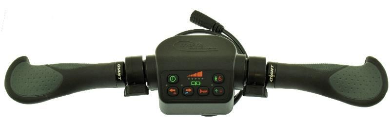
Contents
   Contact & Product ----------------------------------------------------------------------- 2
          mo-Vis bvba------------------------------------------------------------------------ 2
          Scoot Control User & Installation manual ---------------------------------- 2
   Contents ----------------------------------------------------------------------------------- 3
   Important information about this Manual ---------------------------------------- 5
   Support, scrapping and spare parts ------------------------------------------------- 6
   Warranty----------------------------------------------------------------------------------- 7
   Safety precautions ---------------------------------------------------------------------- 9
   Design and function of the Scoot Control --------------------------------------- 12
          Operation of the device ------------------------------------------------------- 13
          Parameters: on-board configuration -------------------------------------- 22
          Intended use --------------------------------------------------------------------- 29
   Installation instructions -------------------------------------------------------------- 30
          Preparations --------------------------------------------------------------------- 30
          Installation ----------------------------------------------------------------------- 32
          Calibration ----------------------------------------------------------------------- 33
          Testing ---------------------------------------------------------------------------- 36
   First time use --------------------------------------------------------------------------- 38
   Using the Scoot Control -------------------------------------------------------------- 39
          Conditions of use --------------------------------------------------------------- 39
          Error codes ----------------------------------------------------------------------- 40
          Fault log --------------------------------------------------------------------------- 41
          R-net Trip Codes ---------------------------------------------------------------- 43
Scoot Control manual                                                                                 3
Maintenance ---------------------------------------------------------------------------- 47
Technical data -------------------------------------------------------------------------- 50
4Important information about this Manual
Thank you for choosing a mo-Vis product!
This is the Manual of your new mo-Vis device. Before you install or
start to use this product, it is important that you read and understand
the content instructions, especially the safety precautions.
The installation instructions will guide you as an installer through the
options and possibilities of this device. The operating instructions are
primarily intended to acquaint you with the functions and the
characteristics of the mo-Vis product and how you can use it in the
best manner possible. They also contain important safety and
maintenance information, as well as a description of possible
problems that can arise during use.
Always keep the operating instructions handy in connection with
your wheelchair, since the need for important information can arise
concerning its use, safety and maintenance.
All information, pictures, illustrations and specifications are based on
the product information that was available at the time of printing.
Pictures and illustrations shown in these instructions are
representative examples and are not intended to be exact depictions
of the various parts of the product. We reserve the right to make
changes to the product without prior notice.
If you would like to learn more about mo-Vis and its products, we
invite you to go to our website: www.mo-vis.com, where you can also
download additional copies of this User & Installation manual.
Scoot Control manual 5Support, scrapping and spare parts
Technical support
Please contact your dealer in case of technical problems. If the dealer
is not available, or unknown, please contact mo-Vis BVBA by email
support@mo-vis.com or by phone +32 9 335 28 60.
Always state the device serial number when contacting mo-Vis. This
ensures you are provided with the correct information.
Spare parts and accessories
Spare parts and accessories must be ordered by the dealer at mo-Vis
BVBA.
Scrapping & recycling
For scrapping, adhere to your local waste legislation.
Dispose of obsolete electronic parts responsibly in accordance with
local recycling regulations.
6Warranty
mo-Vis bv warrants the Scoot Control to be free from defects in
material and workmanship for a period of 2 years under proper use,
care & service. All warranties only cover parts and do not extend
beyond the initial purchaser from an authorised mo-Vis dealer.
Start of the warranty period
Each warranty shall begin on the date the product is first delivered
to the customer.
Repair and replacement
For warranty service, we advise you to contact the dealer from
whom the product was purchased. In the event of a defect in
material or workmanship, the dealer must obtain a return
authorisation (RMA) number from mo-Vis and the product must be
shipped to a service centre designated by mo-Vis. mo-Vis will repair
or, at mo-Vis’ option, replace any product covered by the warranty.
Disclaimer and Limitations of Remedies
The express warranties set forth in this agreement are in lieu of all
other warranties of merchantability or fitness of purpose. In no
event shall mo-Vis be liable for any direct, indirect, incidental or
consequential damages resulting from any defect in this product.
Warranty of parts subject to “normal wear and tear” (e.g. pads,
Scoot Control manual 7joystick balls, batteries …) are not covered in the warranty except as
it applies to defects in material or construction.
Amendments
No person is authorised to alter, extend or waive the warranties of
mo-Vis.
Voiding of warranties
The foregoing warranties are contingent upon the proper
installation, use, maintenance and care of the product. The
warranty will be void if the product has been installed or used
improperly, or if it has been repaired or any part replaced by
persons other than mo-Vis or an authorised dealer. The Scoot
Control, integrated cabling included, is considered as a non-
serviceable part.
The addition of equipment or features that are not manufactured
or recommended by mo-Vis could affect the intended function of
the mo-Vis product and may invalidate the warranty.
Understanding usage
The authorised installer is responsible for understanding the
intended use of the mo-Vis equipment, the specifications and its
programming parameters. mo-Vis cannot be held responsible for
damage caused by incorrect installation or incorrect use of the
product. Misuse, mishandling or storage is not covered by this
warranty.
8Safety precautions
General
The Scoot Control is part of our range of input devices. The main
purpose of the device is to enable the attendant to control a powered
wheelchair. The Scoot Control is to be mounted on the back and is a
steering device with 2 handles (similar to a compact bicycle steer).
The Scoot Control R-net is only compatible with the R-net
electronics of Curtiss-Wright.
Incorrect use or installation may lead to risk of injury to the user and
damage to the wheelchair and other property. In order to reduce
these risks, you should carefully read this manual, especially the
safety instructions and warning texts.
Only install this product on a wheelchair where the wheelchair
manufacturer allows the installation of third party parts.
Any unauthorised use of the product may lead to increased risk of
accident. In case of doubt for alterations and adjustments, always
contact a qualified service engineer.
The Scoot Control, integrated cabling included, is considered as a
non-serviceable part.
In case any serious incident occurs in relation to this device, this
should be reported immediately to mo-Vis and the competent
authority in the Member State in which the user is established.
Scoot Control manual 9Warning labels
The following safety labels are used throughout this manual to draw
attention to items of significant importance to safety.
CAUTION!
Signal word to indicate a hazardous situation which, if not avoided, could
result in damage to the product or to other property.
WARNING!
Signal word to indicate a hazardous situation which, if not avoided could
result in personal injury or property damage.
Safety precautions
CAUTION!
Limited liability: mo-Vis accepts no liability for personal injury or damage
to property that may arise from the failure of the user or other persons to
follow the recommendations, warnings and instructions in this manual.
CAUTION!
EMC Requirements: The Scoot Control complies with the limit values for
Electromagnetic Compatibility (EMC) set out in the harmonised standards
of the Medical Device Directive 93/42/EEC (EU).
10WARNING!
Assembly: The Scoot Control should only be installed or adjusted by a
qualified service engineer or someone with adequate knowledge to perform
the adjustment in an expert manner.
Maintenance and service: Carry out only the service and maintenance
activities specified in this manual. All other service, alterations to and
interventions on the Scoot Control must be carried out by a qualified service
engineer or someone with adequate knowledge to perform the adjustment
in an expert manner. In case of doubt, contact a qualified service engineer
or mo-Vis.
Use only spare parts or accessories approved or recommended by mo-Vis.
All other use could lead to changes which might impair the function and
safety of the product. It could also lead to the warranty becoming void.
CAUTION!
Testing: The Scoot Control should always be tested without any person
sitting in the wheelchair after every alteration of the physical installation
or adjustment of the parameters.
Scoot Control manual 11Design and function of the Scoot Control
Purpose
The Scoot Control is a wheelchair control used by the attendant or
caregiver to control the power chair over long distances outdoor, to
maneuver the chair in tight spaces or to take over the control of the
user in difficult circumstances.
Features
Fully proportional handle bar with 2 rubber handles and 2
configurable thumb throttles at either side.
Built in a compact housing, with a 3.5 mm stereo jack to
connect an external actuator keypad (Curtiss-Wright
CJSM2 compatible).
Full access to wheelchair functions such as Lights, Horn
and Speed settings.
Battery and speed display via LEDs.
On-board configuration possible.
Compatible with multiple types of wheelchair equipped
with R-net electronics.
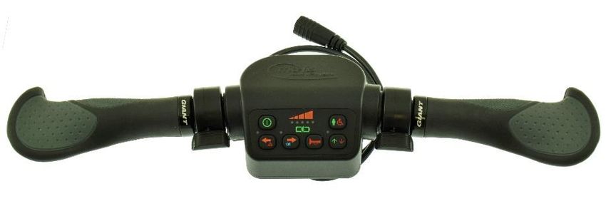
12Operation of the device
Scoot Control P015-61
The Scoot Control consists of the following parts:
Part Location Purpose
Control panel Center Control the Scoot Control
Handle bar Rubber handle Steer the wheelchair
at either side
Thumb throttle One left, Move forward and/or
One right backward
3,5 mm jack Bottom Connect an actuator keypad
(Curtiss-Wright CJSM2
compatible)
Sounder Built-in Use as a horn
Scoot Control manual 13Horizontal movements of the handle bar will result in a steering
action of the wheelchair (turning).
In combination with the thumb throttle (forward/backward) it is
possible to move the wheelchair in any direction. In standard
configuration, the right throttle will move the wheelchair forward
and the left throttle will move the wheelchair backward.
If both throttles are operated simultaneously and that
would result in conflicting directions the chair will stop
driving.
It is possible to configure each throttle separately in the
parameter settings (see on-board configuration).
The Scoot Control will enter in stand-by if not used for 15 seconds
(throttle and handle bar in rest). This is to prevent that accidentally
touching the handle bar results in a sudden movement of the
wheelchair.
When the device is in stand-by or not in focus, it will not be possible
to drive or scroll through the profiles/modes via the Scoot Control.
To exit stand-by mode and reactivate the Scoot Control, move one
of the throttles.
There is an out of neutral detection at start-up and when changing
a profile. If the handlebar/throttle is not in neutral within 10
seconds, an error will be given and further operation of the device is
halted until it is switched off and on again.
14Control Panel
Illustration of the control panel
Scoot Control manual 15The buttons have the following functions:
Button Function Action
S1 On/Off Switch the R-net system on/off
The Scoot Control needs to be switched
on locally in order to get the focus.
S2 Left Indicator Switch left indicator on/off
(switch off right indicator if it was on)
S3 Right Switch right indicator on/off
Indicator (switch off left indicator if it was on)
S2 > 2s Hazard Lights Switch on/off hazard lights
S3 > 2s Lights Switch on/off lights
S4 Horn Horn sounds as long as pressed
An R-net command is send, which
will activate the R-net horn.
If there is no R-net horn available,
the built-in sounder will be used.
S5 Direction Switch direction (see parameters)
S6 Speed Setting Change speed. The first click on S6 will
show you the current speed setting.
Your next clicks will change the speed.
Roll over at the end.
S6 > 2s Grab focus Press long to grab control of the
wheelchair (see § Parameters: on-
board configuration).
16Led indications on the control panel provide you with the following
information:
LED Function Information
D11 Speed Setting Speed indicator when setting speed.
– 5 speeds, 5 green LEDs in a row (e.g.
D15 speed level 3 = 3 LEDs on).
Becomes active when pressing S6 and
remains active for 5 seconds after the
last speed change.
Battery Battery indicator: Led Bar, D11 red,
Gauge D13/D14 orange, D15 Green.
Is default on in focus mode.
Error D11 and D15 red, D13 number of
flashes indicates the fault (RED).
All other LEDs are off!
Status Not In Focus: D13 heartbeat flash
(GREEN)
Configuration: D13 fast flash
(GREEN)
In both cases, all other LEDs are off!
D16 Left Indicator Green flash when left indicator is on
D17 Right Indicator Green flash when right indicator is on
Scoot Control manual 17LED Function Information
D16 Hazard lights/ Both flash red when hazard lights are
+ lights indicator on.
D17 Both are orange when the lights are on
and the direction indicator is off.
D18 Forward/ Forward = Green
Reverse Backward = Orange
No Focus Off
Stand-by Flash Green/Orange
R-net parameters
What we describe here are the standard settings for the Scoot
Control. Please see §Parameters: on-board configuration for all
other options.
Please set the following parameters in R-net before using the Scoot
Control.
R-net: Controls > Global > Power-up Mode (Ch. 3 – 7.12):
set this parameter to Drive to make sure that you start in
the mode Drive when you switch on the Scoot Control.
R-net: Profile Management > Input Device Type (Ch. 3 –
4.4): set this parameter to Attendant and choose ‘No’ for
Allow Grab.
See the Curtiss-Wright manual SK77981-14 |R-net Technical Manual
| Chapter 3 – Programming, for more information.
18Example of the R-net settings:
If you want to combine the Scoot Control with other mo-Vis
joysticks, keep the following in mind:
- For mo-Vis R-net joysticks, you should select ‘JSM’ as ‘Input
Device Type’ and not ‘Universal’.
- For mo-Vis Omni joysticks, you should select ‘Omni’ as ‘Input
Device Type’ and not ‘Universal’.
- If you do choose ‘Universal’, then the Scoot Control will not
be fully functional as an Attendant Control.
Optional: Actuator keypad
You can also connect an external R-net compatible keypad to the
Scoot Control to control the actuators of the Wheelchair, e.g. the
mo-Vis Actuator keypad.
Contact mo-Vis for information on the mo-Vis Actuator keypads
P016-98 & 99 (CJSM2) and the corresponding mounting bracket
M015-91.
Scoot Control manual 19A keypress will send an axis command onto the R-net system. Please
refer to the R-net documentation for actuator settings and controls:
Curtiss-Wright manual SK77981-14 | R-net Technical Manual |
Chapter 3 – Programming.
A parameter is available to control 5 or 10 axes (toggle function: see
§ Parameters: on-board configuration).
Keypad 5 AXIS
Number Command Action
1 AXIS 1 up Move Axis up
2 AXIS 1 down Move Axis down
…
9 AXIS 5 up Move Axis up
10 AXIS 5 down Move Axis down
Keypad 10 AXIS
Number Command Action
1 AXIS 1 toggle Toggle Axis, start with Up
2 AXIS 2 toggle then Down
…
9 AXIS 9 toggle
10 AXIS 10 toggle
20Optional: mounting parts
Contact mo-Vis for information on available mounting parts, and
advice on mounting the device.
The Scoot Control Mounting Bracket (M015-70) is available as
dedicated mounting part.
The Scoot Control Keypad Bracket Set (M015-91) is available to
mount a mo-Vis Actuator Keypad (P016-98 & 99) to the Scoot
Control.
Ordering spare parts
Spare parts and accessories must be ordered by the dealer at
mo-Vis bvba. Always mention Product code & Product description
of items to be ordered.
Scoot Control manual 21Parameters: on-board configuration
A number of parameters is settable on board, without the use of the
mo-Vis Configurator software or peripheral devices.
WARNING
Altering the parameters should only be executed by a qualified
service engineer. Incorrect programming of the device and/or the
wheelchair electronics may cause damage to the device(s), or
injury to the user.
Enter on-board programming mode
Proceed as follows to enter the on-board programming mode:
Step Action
1 Verify the R-net system is switched off
2 Simultaneously press S3,
S4 and S5
3 While S3, S4 and S5 are
pressed, switch the Scoot
Control on using S1
22Step Action
4 Keep S3, S4 and S5 pressed, while you wait for the beep
(5-second delay)
5 Release all buttons within 2 seconds after the beep
Result: You are now in on-board programming mode
If the steps are not followed correctly, you will enter or abort the
calibration process. In that case, D11 – D15 will be flashing red.
Select/change a parameter
Use the following buttons to select/change a parameter:
Button Action
S2 Select previous
parameter
S3 Select next parameter
S4 Decrease value
S5 Increase value
The LEDs of the battery/speed gauge (D11-D15) indicate the
selected parameter/value:
Parameter: LED bar green, parameter 1 to 4
Value: LED bar orange, value 1 to 4
Scoot Control manual 23Save/discard changes
Press S6 to save the changes. All LEDs of the battery/speed gauge will
flash green. Turn the device off and on again.
If the device is switched off without pressing S6, the changes will not
be saved.
Parameter settings
There are five available parameters.
Parameter Name Value Description
Number (Default settings in bold)
1 Throttle Right 1 None – The throttle has
no action
2 Forward
3 Reverse
2 Throttle Left 1 None – The throttle has
no action
2 Forward
3 Reverse
With the first two parameters, you can adjust the default direction
of the throttles.
24Parameter Name Value Description (Default
Number settings in bold)
3 Actuator 1 Single – Each button on
Keypad Setting the keypad will move the
(optional) actuator in one direction
(up or down)
2 Toggle – Each button on
the keypad will move the
actuator up and down
See §Optional: Actuator Keypad.
Parameter Name Value Description (Default
Number settings in bold)
4 Profile/Mode 1 Standard – Use the R-net
setting
2 Profile – Only Profiles
3 Profile/Mode – Always
Profile/Mode
This parameter is only useful, when Parameter #5 is set to
‘Universal’.
With this parameter, you can choose to overrule the R-net settings.
(R-net: Controls > Global > Profile Button (Ch. 3 – 7
Scoot Control manual 255): this parameter can be set to Profile or Profiles/Modes. See the
Curtiss-Wright manual SK77981-14 | Chapter 3 – Programming for
more information.)
E.g. you have chosen Profile/Mode in R-net, but you do not want
that the attendant has the options to go through the modes and
change the actuators for instance. Then you can set this parameter
to Value 2 – Only Profiles.
If you do allow the attendant to be able to go through the modes,
then it is possible to control the axes of the actuators of the
wheelchair through the Scoot Control.
Press S6 > 2 seconds. You scroll through the
profiles/modes. Stop at the seating mode.
In the seating mode, you can scroll through the different
actuators by pressing the handlebar gently. Stop at the
desired actuator.
Move the actuator by pushing the left and right throttle
(the actuator will move up/down according to the
settings of both throttles).
26Parameter Name Value Description (Default
Number settings in bold)
5 Allow Grab 1 Attendant
2 Universal
With this setting you can choose to set the Scoot Control as a
Universal Joystick.
- If the Scoot Control is set as Attendant, then the Scoot Control
will start up in the last used profile. When you press S6 for
more than two seconds, you will go directly to Profile 8. You
have no access to the modes. When you press S6 again for
longer than two seconds, you go back to the other profile and
give the control back to the person in the wheelchair.
- If the Scoot Control is set as Universal, then the Scoot Control
will start up in the last used profile. When you press S6 for
more than two seconds, you scroll through the profiles and
the modes. You can drive in every profile and you can change
the seating positions (optional, see above).
R-net settings for the Scoot Control as Universal Joystick:
Scoot Control manual 27It is very important that you change the settings both in the Scoot
Control (on-board configuration) AND in R-net. E.g. if you set
parameter #5 as ‘Universal’, but you do not change the R-net
settings, that it will not function as it should.
28Intended use
The Scoot Control is a steering device which can be connected
directly to the wheelchair electronics (R-net) to control the
wheelchair and its functions. It is intended to support an attendant
in controlling or manoeuvring a powered wheelchair, both inside and
outside.
Safe driving
WARNING!
The on/off switch must be available to the user at all times. This
allows to instantly stop the wheelchair in case of problems or an
emergency.
In case the wheelchair responds in an unexpected way, the user must
immediately release the Scoot Control or use the power on/off
switch.
WARNING!
Only adult attendants should operate the Scoot Control.
Scoot Control manual 29Installation instructions
Preparations
Tools
CAUTION!
Use the proper tools to install and adjust the Scoot Control. The
use of improper tools may cause damage to the device.
CAUTION!
Do not tighten screws with an excessive force.
Installation plan
Set up an installation plan before starting the installation. Based on
the users’ needs and capabilities of the wheelchair and user, this
plan should take into account:
At which position (height, inclination …) the Scoot
Control should be placed.
How the Scoot Control will be operated: parameter
settings
A robust and reliable positioning. Hard or sudden
movements of the wheelchair may not disorganise the
installation.
30CAUTION!
Protect the device against bumps.
WARNING!
Avoid hitting obstacles during driving.
WARNING!
Mind damaging the unit and wiring. Make sure that cabling is
mounted in such a way that excessive wear and tear is avoided.
CAUTION!
Any connection must always be secured with all delivered screws.
Only use the screws provided in the package.
Serial number sticker
The additional serial number sticker which can be found in the
package should be adhered to the back of this manual.
Scoot Control manual 31Installation
1. Mount the unit with suited mounting parts at the desired
location. If necessary, adjust the angle and the height of the
handlebar to fit the user’s position.
Contact your dealer or mo-Vis for more information.
CAUTION!
You can adjust the position of the handlebar by loosening the
screws at the sides of the handles. Afterwards, screw them up
again with a maximum torque of 1 Nm.
2. Place and secure all cabling on the wheelchair.
3. Connect the cabling to the wheelchair electronics.
WARNING!
All wheelchair electronics must be switched off during
installation.
32Calibration
CAUTION!
Only when you experience asymmetrical movement and after
every change or repair of the device, a qualified service engineer
should recalibrate the device in order to guarantee a proper
functioning.
Enter the on-board calibration mode
Proceed as follows to enter the on-board calibration mode:
Step Action
1 Verify the R-net system is switched of
2 Verify that the throttles and steering bar are in neutral.
3 Simultaneously press S2,
S3 and S4
4 While S2, S3 and S4 are
pressed, switch the Scoot
Control on using S1
5 Wait for the beep (5-second delay)
6 Release all buttons within 2 seconds after the beep
Result: You are now in on-board calibration mode
Scoot Control manual 33If the steps are not followed correctly, you will enter or abort the
calibration process. In that case, D11 – D15 will be flashing red.
Execute on-board calibration
The calibration process consists of multiple stages.
The stage number is indicated by the number of LEDs
(D11-D15) coloring green.
Each stage can have multiple steps.
Every time you hear a beep, you should release the
handlebar and only proceed with the next action when
you see that the corresponding LED is turned on.
Stage Input Step Action
1 green Throttle right 1 Full throttle right and wait
for beep
2 Release throttle right
2 green Throttle left 1 Full throttle left and wait
for beep
2 Release throttle left
3 green Handlebar right 1 Full handlebar right and
wait for beep
2 Release handlebar right
4 green Handlebar left 1 Full handlebar left and
wait for beep
2 Release handlebar left
34Stage Input Step Action
5 green Calibration was successful and the new calibration
data is stored in the device
5 red Calibration aborted or failed and no calibration data
is changed in the device
WARNING!
If the calibration was successful, please proceed to check if the
movement of the wheelchair is symmetrical when moving the
handlebar to both sides. Check if the device returns to its default
position.
Scoot Control manual 35Testing
After installation of the Scoot Control, execute the following tests
before the wheelchair is delivered or put into service, in according
order:
1. Check the Scoot Control for intactness
2. Operational test
3. Test drive
4. Stop test
Check the Scoot Control for intactness
Check whether:
The device is not bent or damaged
Housing, cabling and all connectors are not damaged
The device returns to its default position when moving
and releasing the device forward, backward, left and
right.
Operational test
WARNING!
Execute this test only on a level surface, with at least one meter of
free space around the wheelchair.
36Test drive
Make a test drive with the wheelchair.
Check whether the wheelchair and all its functionalities
function fully correctly in all positions the
user/attendant may use the Scoot Control.
Check no cabling or parts may get damaged or hindered
in any possible position of the wheelchair.
Stop test
Drive full speed ahead and shut down the wheelchair with the
power on/off switch. The wheelchair may not suddenly stop, but
must slow down to a gradual stop.
Scoot Control manual 37First time use
Dealer assistance
During first time use by the user it is advised that the dealer or
service engineer assists and explains the different possibilities to
the customer (the user of the attendant control).
If needed, the dealer can make final adjustments.
User testing
It is important that the customer is fully aware of the installation,
how to use it and what can be adjusted to optimise his experience.
As a dealer, proceed as follows:
1. Explain and show the customer how you have executed the
installation, and explain the function of every (new) button.
2. Have the user test all positions of the Scoot Control:
Is the Scoot Control and buttons within easy reach?
Can the user safely operate the wheelchair with the least
effort?
Is the placement of the device in all available positions
optimal for the user?
3. If needed, adjust the position and the settings of the Scoot
Control.
4. Explain to the customer possible problems and how to address
them.
38Using the Scoot Control
Conditions of use
The Scoot Control is intended for use as installed by the dealer, in
accordance to the installation instructions in this manual.
The foreseen conditions of use are communicated by the dealer or
service engineer to the user and/or attendant during the first time
use.
If the conditions of use change significantly, please contact your
dealer or a qualified service engineer to avoid excessive wear and
tear or unintended damage.
Scoot Control manual 39Error codes
When a fault occurs, the LED of the Scoot Control will start to flash.
A long delay is followed by a number of flashes with a short delay.
Count the number of flashes and look in the table below:
Flash count Reason Required action
1 - -
2 Hall Sensor Left Replace Sensor Board & Calibrate
3 Hall Sensor Right
4 Throttle Left Replace Throttle Sensor & Calibrate
5 Throttle Right
6 Test Flag failed Redo diagnostic tests
7 CPU Fault Replace PCB
8 Code Fault Update Firmware
Replace PCB
9 Software Watchdog Update Firmware
Replace PCB
10 R-net Failure Check R-net configuration, check
fault log in the R-net PC
programmer
11 Diagnostic Test Test Failed, redo test
40Fault log
The system maintains a fault log with counters. The fault log can be
accessed via the mo-Vis Configurator (Dealer Level). In that case,
please contact mo-Vis for further instructions.
Fault Reason Required action
CPU Error RAM CPU consistency check Replace PCB.
CPU Error FLASH failed.
CPU Error STACK
CPU Error
EEPROM
Watchdog Reset The watchdog kicked in. Update Firmware or
Hard Fault A hard fault in the CPU Replace PCB.
Unexpected Case An invalid case
occurred.
Null Pointer An invalid pointer
occurred.
Unexpected Value Unknown command
was received.
Out Of Bounds Access to an invalid
memory location.
Scoot Control manual 41Fault Reason Required action
MSP Slave Communication Connection with the PC
Problem (Configurator program)
went wrong. Update
Firmware or update
Configurator Software. Try
again.
PCB Test Factory test failed. A fault occurred during
factory testing.
Field Test Field test failed A fault occurred during field
(Calibration). testing (Calibration).
Test Flags One or more test flags Redo tests and/or replace
not set. PCB.
Software wdt Software Watchdog Update Firmware
Replace PCB
Hall Sensor Left The left sensor is faulty. Replace sensor and
Hall Sensor Right The right sensor is calibrate.
faulty.
Throttle Left The left throttle is Replace throttle and
faulty. calibrate.
Throttle Right The right throttle is
faulty.
R-net Trip Code There is an R-net Trip Check R-net fault on
Code joystick display or in the R-
net PC Programmer
42R-net Trip Codes
When a fault is detected by the Scoot Control, an R-net trip fault
will be generated. The Trip Code will be shown on the joystick (if it
is present and equipped with a graphic display). The Trip Code will
also be logged in the R-net system and can be investigated using the
R-net PC Programmer.
If you want to learn more about Trip Codes, see the Curtiss-Wright
manual: SK77981-14 R-net Technical Manual | Chapter 3 –
Programming.
Application Trip Codes
R-net Trip Code Reason Required action
9600 Uart overflow Update Firmware or
9601 Uart underflow Replace PCB
9602 Packet transmission
exceeded maximum
number of retries
9603 TX handle overflow
9604 RX handle overflow
9605 Invalid sequence
number
9606 Ack number does not
match
Scoot Control manual 43R-net Trip Code Reason Required action
9607 Invalid packet
descriptor
9608 Incorrect R-net version
9609 Chip tripped
960A Invalid response when
accessing a file
9620 CPU Error
9621 Code Error
9640 One or more test flags Redo tests and/or replace
not set. PCB.
9641 Software Watchdog Update Firmware or
Replace PCB.
9642 There was a problem Check R-net fault on
during the preparation joystick display or in the
of the R-net system. R-net PC Programmer.
Check R-net
configuration.
9643 The left sensor is faulty. Replace sensor board and
9644 The right sensor is calibrate.
faulty.
9645 The left throttle is Replace throttle and
faulty. calibrate.
44R-net Trip Code Reason Required action
9646 The right throttle is
faulty.
9647 There is an R-net Trip Check R-net fault on
Code. joystick display or in the
R-net PC Programmer.
9648 Factory test failed. A fault occurred during
factory testing.
9649 Field test failed A fault occurred during
(Calibration). field testing (Calibration).
Chip Set Trip Codes
R-net Trip Code Reason Required action
9800 API_MSG_SEND_TO_FREQ Update Firmware or
UENTLY Replace PCB, check R-
9801 API_MSG_DATA_OUT_OF_ net configuration
RANGE
9802 API_MSG_ID_UNKNOWN
9803 API_MSG_DATA_INCORREC
T_AMOUNT
9804 API_MSG_TOO_SHORT
9805 API_MSG_TOO_LONG
9806 API_MSG_NOT_ENABLED
Scoot Control manual 45R-net Trip Code Reason Required action
9807 API_RESPONDED_OUT_OF_
TIME
9808 API_MSG_REQUIEREMENT_
WRONG
9809 API_MSG_INVALID_IN_CUR
RENT_STATE
9810 DATA_PACKET_WITH_INVA
LID_SEQ_NR
9811 ACK_PACKET_WITH_INVALI
D_SEQ_NR
9812 INVALID_HEADER
9813 PACKET_TIMEOUT
9814 CHIP_INT_ERR0
9815 CHIP_INT_ERR1
9816 HOST_RESTART_AFTER_CO
RRECT_INIT
9817 HOST_INCOMPATIBLE_SERI
AL_PROTOCOL_VERSION
9820 CHIPSET_INTERNAL_QUEUE
_OVERFLOW
9821 CHIPSET_HEARTBEAT
46Maintenance
Cleaning
Clean all parts of the Scoot Control on a regular basis (monthly), or
whenever needed.
Gently remove dust and dirt with a damp cloth
Use only non-aggressive disinfectant cleaning agents
WARNING!
Do not immerse in water or use excessive amounts of liquid.
CAUTION!
Do not apply additional lubricants to the moving parts.
Monthly check
Monthly, or whenever needed, check whether:
All bolts and screws are still firmly tightened
There is no damage to any wiring
There is no excessive wear to any of the parts
Scoot Control manual 47Yearly check
We advise to have at least yearly a full check of the wheelchair and
its operating systems by a qualified service engineer.
Contact your local dealer or mo-Vis for more information.
Maintenance free
The Scoot Control is maintenance-free. Under regular use
circumstances, the device and different parts do not require
additional maintenance.
48Scoot Control manual 49
Technical data
Product description & Code
Scoot Control R-net (P015-61)
Scoot Control Mounting Bracket (M015-70)
Scoot Control Keypad Bracket Set (M015-91)
Actuator Keypad Button R-net CJSM2 (P016-98)
Actuator Keypad Paddle R-net CJSM2 (P016-99)
Device connectors
3.5 mm stereo jack (actuator panel)
Mini USB (internal)
R-net Wheelchair connector
50Specifications
Factor Specification
Electronics Curtiss-Wright R-net Compatible
Input Keypad Curtiss-Wright CJSM2 compatible keyboard (34E)
Cable Length Pigtail 600 mm / 23.62 in R-net male pin connector
Throttle Force 300 g / 10.58 oz (3,000 g / 6.61 lb Safe Overload)
Keyboard force 100 g /3.53 oz (1,000 g / 2.20 lb Safe Overload)
Handlebar force 2.500 g /5.51 lb (25,000g / 55.12 lb Safe Overload)
Weight 1.250 g / 2.76 lb
Dimensions 450 x 100 x 55 mm / 17.72 x 3.94 x 2.17 in (WxDxH)
Mounting 4 * M6 (8 mm depth) in a square (55 x 55 mm / 2.17 x
2.17 in))
Scoot Control manual 51Installation date: . . / . . / . . . .
Dealer: . . . . . . . . . . . . . . . . . .
Dealer stamp:
Serial number sticker
52You can also read