Azimuth optimizer User manual Bedienungsanleitung - Picture similar / Abbildung ähnlich - Clearaudio
←
→
Page content transcription
If your browser does not render page correctly, please read the page content below
azimuth optimizer
User manual
Bedienungsanleitung

Picture similar /
Abbildung ähnlich

© clearaudio electronic GmbH, 2021-07						   Made in Germany
User manual / Bedienungsanleitung

       User manual................................................... 2 - 4

       Bedienungsanleitung..................................... 5 - 7

Dear Clearaudio customer,

You have purchased a truly high-end-product made by Clearaudio electronic - Germany.
These operating instructions provide valuable advice for the correct use of the azimuth optimizer.
Thank you for choosing a Clearaudio product.

We wish you a lot of pleasure with your azimuth optimizer.

Your Clearaudio electronic GmbH

                                                  Warning
Do not expose the equipment to rain or moisture.
Do not handle the mains lead with wet hands.
No naked flame sources, such as lighted candles, should be placed on the equipment.

CE-MARKIERUNG

      The Clearaudio azimuth optimizer conforms to the EMC regulations.

Page / Seite 2					                                                    © clearaudio electronic GmbH, 2021-07
User manual / Bedienungsanleitung
Contents
1. List of components.............................................4
2. Functional description........................................5
3. Operating elements............................................6
4. Measurement operation.....................................7
5. Technical specification.......................................8
6. Service................................................................9
Warranty information.............................................18
Made in Germany Page / Seite 3User manual / Bedienungsanleitung
1. List of components
The Clearaudio azimuth optimizer has left our factory in safe packing that has been specially
designed for this product. We recommend you store this original packing and to use this packing in
case of any transportation. Please check if the parts listed below have been enclosed:
azimuth optimizer unit Clearaudio azimuth optimizer test
1. 4.
record
2. Power supply 5. User manual
Power supply adaptors (1x US, 1x Warranty & Registration Card
3. 6.
UK, 1 Europe)
Phonostages are devices designed to provide a very high level of amplification. This is necessary
because the electrical signal generated by a phono cartridge is extremely low (usually less than one-
thousandth of a volt). The job of the phonostage is therefore to accurately equalise the phono signal
and boost it to line level (measured in volts).
However, phonostages are by nature extremely sensitive, which leads to the potential problem that
high-frequency interference may also be amplified to a point at which it becomes noticeable.
Unfortunately it is not possible to completely protect the sensitive phonostage circuitry from this
interference without degrading its high fidelity performance. Therefore care must be taken to position
the phonostage away from sources of high frequency interference such as mobile phones, modems
and powerline communication systems (PLC) in which data is sent over the mains power network.
Page / Seite 4 © clearaudio electronic GmbH, 2021-07User manual / Bedienungsanleitung
2. Functional description
The Azimuth (the vertical position of the cartridge‘s diamond) is the main influence on channel
balance, the frequency response and the cross talk between both channels of your cartridge.
Optical control of the azimuth adjustment is not sufficient nor precise enough to ensure accurate
adjustment of the cartridge’s azimuth. The exact azimuth can only be determined when using
an adequate measuring instrument like Clearaudio`s azimuth optimizer. The azimuth optimizer
measures the cross-talk from the left to the right channel and vice versa. The ideal cartridge position
is when the azimuth has been adjusted accurately so that both measurement results are identical.
Additionally, you can measure the output voltage of your cartridge by using the operation mode
« Level » To use this operation mode it is necessary to set the input sensitivity to the MM-mode!
Further more there is a High-End phono-pre-amplifier built in as well, so that you are able to check
the sonical result of the correct adjustment in your music reproduction system.
An integrated head-phone amplifier makes mobile use of the azimuth optimizer possible!
All headphones with an impedance between 100 ohms and 600 ohms can be used.
The Clearaudio azimuth optimizer test record (Art. No.: LPT Azimuth 080108) is necessary to
perform the measurements and is included with your Optimizer.
For measurement, the following tracks of the azimuth optimizer test record are required:
Track 1 = Signal left channel 1kHz 0dB = 10cm/s (Peak)
Track 2 = Signal right channel 1kHz 0dB = 10cm/s (Peak)
…
Track 19 = Signal left channel 1kHz 0dB = 10cm/s (Peak)
Track 20 = Signal right channel 1kHz 0dB = 10cm/s (Peak)
Connections at the back panel:
INPUT LEFT; INPUT RIGHT:
Connect with the tonearm of the
INPUT LEFT INPUT RIGHT OUTPUT LEFT OUTPUT RIGHT record player
OUTPUT LEFT; OUTPUT RIGHT:
Connect with the preamplifier
GROUND POWER SUPPLY
DC 24 VOLT
GROUND:
Connect the grounding cable of
the tonearm
POWER SUPPLY:
Connect the power supply (24V
type:FW75550/24)
Made in Germany Page / Seite 5User manual / Bedienungsanleitung
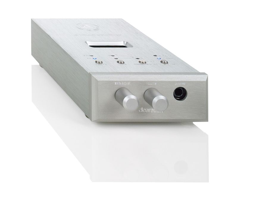
3. Operating elements
Button MM/MC:
Switches the input sensitivity / amplification.
Position MM = 40dB,
Position MC = 60dB
Input impedance/Capacity:
MM = 47kOhm/220pF
MC = 400Ohm/220pF,
(the input impedance is adjusted
automatically).
Button L/R:
azimuth optimizer Switches to the signal-carrying channel of
the test-record
Button Crosstalk:
Activates the operation mode „Crosstalk“
Button „Level“:
Pushing the button ‘Level’ will in
combination with the test-record show the
output voltage of your cartridge in the
MC R
R L
AZIMUTH display in mV.
MM L
L R
CT PHONO
Pushing both buttons ‘Level’ and
‘Crosstalk’ simultaneously, the main
AZIMUTH
operation mode switches between
MM / MC L/R CROSSTALK / dB LEVEL / mV
“Phono” and “Measurement”.
In the measurement-operation mode the
LED “Azimuth” glows blue
0dB-adjustment
headphone-volume control
Page / Seite 6 © clearaudio electronic GmbH, 2021-07User manual / Bedienungsanleitung 4. Measurement operation Important note! Be sure that the volume control of your amplifier(s) is (are) set to zero-level while doing any connections to the azimuth optimizer unit. While using the azimuth optimizer in a system as a phono-stage, never switch between MM/MC - mode, damage to your loudspeakers could occur! 1. Attach the adequate primary adaptor onto the power supply 2. Connect the power supply to the appropriate jack on the back-panel of the azimuth optimizer 3. Connect the power supply to the mains socket, the azimuth optimizer automatically sets into operation mode MM and Phono. Now connect the tonearm cable with the azimuth optimizer and for playback with the music reproduction system. 4. Choose the relevant operation mode according to your cartridge type: MM or MC. You can now start with the measurement once all connections have been done correctly. 5. Place the Clearaudio azimuth optimizer test record’ (scope of delivery) onto the turntable platter with side 1 facing up. Track 1-20 of the test record can be used to adjust and verify the azimuth of the cartridge: Track 1 = Signal left channel 1kHz 0dB = 8cm/s (peak) Track 2 = Signal right channel 1kHz 0dB = 8cm/s (peak) … Start your measurement with the left channel (Track 1). Therefore choose the operation mode “L” by pushing the button “L/R”. Calibrate the value shown in the display to 0dB by using the control unit in the front panel. When you now push and hold the „Crosstalk“- button the LED ‘CT’ will glow and the channel mode switches to ‘R’ - channel. The display will now show the value of the cross talk in dB. Keep this value in mind and repeat the measurement in the same way with the right channel (Track 2). Now compare both measurement values with each other. When both values are equal the azimuth adjustment is accurate. If the values differ from each other you need to re-adjust the azimuth of your cartridge according to the table below and repeat the measurement until both values are equal. Before measuring the cross-talk it is important to adjust the signal-carrying channel to 0dB! Made in Germany Page / Seite 7
User manual / Bedienungsanleitung

Follow these advises to adjust the azimuth:

measurement                  Left channel (display)      Right channel (display) Direction of cartridge-
                                                                                 rotation
L – R (Track 1)              0                           -30dB
                                                                                    Azimuth is O.K.
R – L (Track 2)              -30dB                       0
L–R                          0                           -35dB                     Rotate cartridge
R-L                          -25dB                       0                              clockwise
L-R                          0                           -25dB                          Rotate cartridge
R-L                          -35dB                       0                             counter clockwise

Note:
The measurement values in the table are only used as examples and can be different depending on
the type of cartridge.

5. Technical data:

Operating Voltage:                                       24V DC stabilised with power supply
                                                         Input: 100-240V~ / 47-63Hz
In- and Outputs:                                         RCA-sockets, unsymmetrically
Phono-unit:
Amplification:              MM = 40dB, MC = 60dB
Channel separation:		       > 80dB
Distortion factor:          < 0,01% / 1kHz
Input impedance/Capacity:
                            MM = 47kOhms / 220pF
				                        MC = 400Ohms / 220pF

Output impedance:			                                     100Ohms
Frequency response:		                                    20Hz – 70kHz /-3dB
RIAA:					                                               RIAA +/- 0,5dB deviation
Headphone output:
Amplification:                                           10dB
Headphone impedance:		                                   100 – 600 Ohm
Connection:                                              6,3 mm-bushing
Measurement unit:
Indication range:		                                      -50 till +6dB, accuracy +/-0.2dB
				                                                     Gauge-measurement up to max. 19,99mV
Noise filter:                                            from 200Hz / transconductance 12dB per octa-
                                                         ve (valid only for right channel when unit is in
                                                         measurement use
Dimensions: H x W x D		                                  47 x 102 x 190mm
Weight:                                                  azimuth optimizer: 750g
                                                         Power supply: 150g
* Provided that the warranty card is correctly completed and returned to Clearaudio, or your product is registered
online at https://clearaudio.de/en/service/registration.php, within 14 days of purchase.

Page / Seite 8					                                                   © clearaudio electronic GmbH, 2021-07
User manual / Bedienungsanleitung 6. Service In case of any necessary service for all Clearaudio products should be done by authorized personal only. In case of any repair, the Clearaudio azimuth optimizer needs to be send to your local dealer or distributor- Please send / ship the azimuth optimizer always and only in the original packing! Only in the original packing Clearaudio can provide the warranty. Made in Germany Page / Seite 9
User manual / Bedienungsanleitung

Sehr geehrte clearaudio Kundin, sehr geehrter clearaudio Kunde

Sie haben sich für den azimuth optimizer entschieden – ein hochwertiges, deutsches Qualitätsprodukt
der Firma clearaudio – wir beglückwünschen Sie dazu und danken Ihnen für das in uns gesetzte
Vertrauen.

Wir wünschen Ihnen viel Freude mit Ihrem neuen clearaudio azimuth optimizer.

Ihre clearaudio electronic GmbH

                                           Warnung

Das Gerät nicht Regen oder Feuchtigkeit aussetzen.
Das Netzkabel nicht mit feuchten oder nassen Händen anfassen.
Es dürfen keine Gegenstände mit offener Flamme, wie etwa brennende Kerzen, auf dem Gerät
aufgestellt werden.

CE-MARKIERUNG

      Der clearaudio azimuth optimizer entspricht den Bestimmungen über elektromagnetische
      Störfreiheit (EMC) und denen über Niederspannungsgeräte.

Page / Seite 10					                                        © clearaudio electronic GmbH, 2021-07
User manual / Bedienungsanleitung
Inhaltsverzeichnis
1. Lieferumfang......................................................... 12
2. Funktionsbeschreibung......................................... 13
3. Bedienelemente..................................................... 14
4. Inbetriebnahme..................................................... 15
5. Technische Daten.................................................. 16
6. Service................................................................... 17
Garantieinformationen.............................................. 18
Made in Germany Page / Seite 11User manual / Bedienungsanleitung
1. Lieferumfang
Der clearaudio azimuth optimizer verlässt unsere Fertigung in einer besonders sicheren und eigens
für dieses Produkt konzipierten Verpackung. Bewahren Sie diese Verpackung auf, um jederzeit einen
sicheren Transport Ihres Gerätes zu gewährleisten.
Bitte kontrollieren Sie anhand der unten aufgeführten Listung den Lieferumfang Ihres neu erworbenen
clearaudio azimuth optimizer.
Dieser besteht aus:
azimuth optimizer unit clearaudio azimuth optimizer
1. 4.
Testrecord
Steckernetzteil Eingang 100-240V~ / Bedienungsanleitung
2. 5.
Ausgang 24V DC
1 Primäradapter EU-Plug Garantiekarte
3. 1 Primäradapter USA-Plug 6.
1 Primäradapter UK-Plug
Phonovorverstärker sind Geräte mit einer hohen Signalverstärkung, da die Spannung die der
Tonabnehmer des Plattenspielers liefert sehr niedrig ist (im Bereich von einigen µV).
Aus diesem Grund werden auch hochfrequente Störsignale wahrnehmbar verstärkt.
Eine vollständige Abblockung dieser Störsignale im Gerät würde die Audioeigenschaften
verschlechtern.
Das hat zur Folge, dass hochfrequente Störungen, zum Beispiel aus dem 230 V Netz bzw. 115 V
Netz, die Klangqualität beeinträchtigen könnte.
Das Gerät sollte daher nicht in der Nähe von Hochfrequenzerzeugenden Geräten wie z.B.
Mobiltelefonen oder Modems bzw. an Stromnetzen die für Datenverkehr genutzt werden (PLC),
betrieben werden.
Page / Seite 12 © clearaudio electronic GmbH, 2021-07User manual / Bedienungsanleitung
2. Funktionsbeschreibung
Der Azimuth (vertikale Position des Abtast-Diamanten) ist maßgeblich für den Kanalgleichlauf,
den Frequenzverlauf, sowie das Übersprechen zwischen beiden Kanälen ihres Tonabnehmers
verantwortlich. Alleine die optische Kontrolle des Tonabnehmers ist nicht ausreichend für eine
korrekte Azimuth-Einstellung. Die exakte Position lässt sich nur mit Hilfe eines Messgerätes ermitteln.
Der azimuth optimizer misst das Übersprechen vom linken zum rechten Kanal und umgekehrt.
Im Idealfall, wenn der Azimuth korrekt eingestellt ist, sollten beide Messwerte gleich sein.
Zusätzlich können Sie mit der Funktion „Level“ die Ausgangsspannung ihres Tonabnehmers prüfen.
Für diese Messfunktion muß die Eingangsempfindlichkeit auf Stellung MM stehen. Der azimuth
optimizer hat einen hochwertigen Phonovorverstärker eingebaut, mit dem sich im Phono-Betrieb die
korrekte Einstellung sofort über die Anlage klanglich überprüfen lässt.
Zusätzlich besteht die Möglichkeit über den eingebauten Kopfhörerverstärker das Signal abzuhören,
somit kann das Gerät auch für den mobilen Einsatz verwendet werden.
Es können Kopfhörer mit einer Impedanz von 100 Ohm bis 600 Ohm angeschlossen werden.
Für die Messungen benötigen Sie unsere clearaudio azimuth optimizer Testrecord
(Best.-Nr. LPT Azimuth 080108).
Auf Seite 1 werden die Tracks 1 bis 20 gebraucht.
Track 1 = Signal linker Kanal 1kHz 0dB = 10cm/s (Spitze)
Track 2 = Signal rechter Kanal 1kHz 0dB = 10cm/s (Spitze)
…
Track 19 = Signal linker Kanal 1kHz 0dB = 10cm/s (Spitze)
Track 20 = Signal rechter Kanal 1kHz 0dB = 10cm/s (Spitze)
Anschlüsse auf der Rückseite:
INPUT LEFT; INPUT RIGHT:
Anschluß für Plattenspieler
INPUT LEFT INPUT RIGHT OUTPUT LEFT OUTPUT RIGHT
OUTPUT LEFT; OUTPUT RIGHT:
Ausgang zum Vorverstärker
POWER SUPPLY
GROUND:
GROUND
DC 24 VOLT
Erdungsanschluß für Tonarm
POWER SUPPLY:
Anschluß für 24 V-Steckernetzteil
Made in Germany Page / Seite 13User manual / Bedienungsanleitung
3. Bedienelemente
Taste MM/MC:
Umschaltung der Eingangsempfindlichkeit
bzw. Verstärkung.
Stellung MM = 40dB,
Stellung MC = 60dB
Eingangswiderstand/Kapazität MM =
47kOhm/220pF
MC = 400Ohm/220pF, der
Eingangswiderstand wird automatisch
umgeschaltet.
azimuth optimizer Taste L/R:
Umschaltung des signalführenden Kanals
auf der Messschallplatte
Taste Crosstalk:
zum Aktivieren der Messfunktion „Crosstalk“
(Übersprechen)
Taste „Level“:
durch Drücken der Taste „Level“ wird in
MC R
R L
AZIMUTH Verbindung mit unserer Messschallplatte der
MM L
L R
CT PHONO
Ausgangspegel ihres Tonabnehmersystems
in mV angezeigt.
AZIMUTH
Durch gleichzeitiges Drücken der Taste
„Level“ und „Crosstalk“ wird zwischen
dem Phonobetrieb und Messbetrieb
MM / MC L/R CROSSTALK / dB LEVEL / mV
umgeschaltet.
Im Messbetrieb leuchtet die LED „Azimuth“
0dB-Abgleich
Kopfhörerlautstärke
Page / Seite 14 © clearaudio electronic GmbH, 2021-07User manual / Bedienungsanleitung
4. Inbetriebnahme
Wichtiger Hinweis!
Achten Sie darauf, das bei allen Verkabelungsarbeiten, der Lautstärkeregler ihres
Verstärkers auf Null steht. Schalten Sie niemals während des Betriebs zwischen MM/
MC um, da durch das Schaltgeräusch ihre Lautsprecher beschädigt werden können.
1. Stecken Sie den passenden Primäradapter auf das Steckernetzteil.
2. Verbinden Sie das Netzteil mit der rückseitigen Buchse am azimuth optimizer.
3. Schließen Sie das Gerät am Stromnetz an, der azimuth optimizer schaltet automatisch auf
Stellung MM und in den Phonobetrieb. Verbinden Sie jetzt den azimuth optimizer mit ihrem
Plattenspieler bzw. mit der Anlage.
4. Wählen Sie die für ihren Tonabnehmer passende Betriebsart MM oder MC.
Wenn alle Verbindungen korrekt hergestellt sind, können Sie mit den Messungen beginnen.
5. Legen Sie die mitgelieferte clearaudio azimuth optimizer Testschallplatte auf ihren Plattenspieler.
Zum Einstellen und Überprüfen des Azimuth werden Track 1 bis 2 benötigt.
Track 1 = Signal linker Kanal 1kHz 0dB = 10cm/s (Spitze)
Track 2 = Signal rechter Kanal 1kHz 0dB = 10cm/s (Spitze)
...
Track 19 = Signal linker Kanal 1kHz 0dB = 10cm/s (Spitze)
Track 20 = Signal rechter Kanal 1kHz 0dB = 10cm/s (Spitze)
Als erstes machen Sie die Messung auf dem linken Kanal (Track 1), stellen Sie dazu am azimuth
optimizer auf „L“. Gleichen Sie mit dem frontseitigen Regler die Anzeige auf 0dB ab, wenn jetzt die
„Crosstalk-Taste“ gedrückt wird, leuchtet die LED „CT“ auf und die Kanalanzeige wechselt auf
„R“. Der Wert, der jetzt am Display angezeigt wird, gibt das Übersprechen in dB an.
Merken Sie sich den Wert und wiederholen Sie nun die Messung in der gleichen Weise auf dem
rechten Kanal (Track 2).
Vergleichen Sie nun die beiden Messwerte miteinander. Wenn der Azimuth ihres Tonabnehmers
korrekt eingestellt ist, müssen beide Werte gleich sein. Sollten die Werte voneinander abweichen,
müssen Sie ihren Tonabnehmer wie in der Tabelle angegeben verstellen und die Messung zur
Kontrolle wiederholen.
Wichtig ist, immer den signalführenden Kanal auf „0dB“ abzugleichen, bevor das
Übersprechen gemessen wird.
Die maximale Eingangsspannung (0dB-Regler auf Linksanschlag, Display zeigt 0dB)
beträgt bei Stellung: MM = ca. 20mV
MC = ca. 2,5mV
Made in Germany Page / Seite 15User manual / Bedienungsanleitung
Für die Einstellung des Azimuth gelten folgende Regeln:
Messung linker Kanal (Anzeige) rechter Kanal (Anzei- Drehrichtung des
ge) Tonabnehmers
L – R (Track 1) 0 -30dB
Azimuth in Ordnung
R – L (Track 2) -30dB 0
L–R 0 -35dB im Uhrzeigersinn
R-L -25dB 0 drehen
L-R 0 -25dB gegen Uhrzeiger-
R-L -35dB 0 sinn drehen
Hinweis:
Die angegebenen Messwerte sind nur Beispiele und können je nach verwendetem Tonabnehmer
abweichen.
5. Technische Daten
Betriebsspannung: 24V Gleichspannung stabilisiert über
Steckernetzteil mit auswechselbaren
Primäradaptern Eingang 100-240 V~ 47-63 Hz
Ein- und Ausgänge: Cinch-Buchsen unsymmetrisch
Phonoteil:
Verstärkung: MM = 40 dB, MC = 60 dB
Fremdspannung: MM = 84 dB(A), MC = 65 dB(A)
Kanaltrennung: > 80 dB
Klirrfaktor (THD+N): < 0,01 % / 1 kHz
Eingangswiderstand / Kapazität: MM = 47 kOhm / 220 pF
MC = 400 Ohm / 220 pF
Ausgangswiderstand: 100 Ohm
Frequenzgang: 20 Hz – 70 kHz /-3 dB
Entzerrung: RIAA +/- 0,5 dB Abweichung
Kopfhörerausgang:
Verstärkung: 10 dB
Kopfhörerimpedanz: 100 – 600 Ohm
Anschluss: 6,3 mm-Klinkenbuchse
Messteil:
Anzeigebereich: -50 bis +6 dB, Genauigkeit +/-0,2 dB
Pegelmessung bis max. 19,99 mV
Rumpelfilter: ab 200 Hz / Steilheit 12 dB pro Oktave
(nur im Messbetrieb wirksam auf dem rechten
Kanal)
Abmessungen: H x B x T 47 x 102 x 190 mm
Gewicht: azimuth optimizer 750 g
Netzteil 150 g
* Nur bei korrekt ausgefüllter und eingesandter Garantiekarte an clearaudio oder online registrierter Garantie
innerhalb von 14 Tagen.
Page / Seite 16 © clearaudio electronic GmbH, 2021-07User manual / Bedienungsanleitung 6. Service Ist eine Reparatur erforderlich, kontaktieren Sie bitte Ihren Fachhändler vor Ort. Sollte ein Versand notwendig sein ist dabei unbedingt auf korrekte bzw. sichere Verpackung zu achten (Originalverpackung). Made in Germany Page / Seite 17
User manual / Bedienungsanleitung

The full, extended warranty period for the azimuth optimizer is 3 years.
To receive this full Clearaudio warranty, you must either complete and return the relevant section of the warranty
registration card to Clearaudio, or register your product online at https://clearaudio.de/en/service/registration.php,
within 14 days of purchase. Otherwise only the legal warranty of 1 years can be considered.
The full 2 year warranty can only be honoured, if the product is returned in its original packing.

Um für den azimuth optimizer die volle clearaudio Garantie von drei (3) Jahren in Anspruch nehmen zu können,
senden Sie uns bitte die beigelegte Garantiekarte innerhalb von zwei Wochen korrekt und vollständig ausgefüllt zu oder
registrieren Sie das Produkt online unter https://clearaudio.de/de/service/ registration.php, da sonst nur die gesetzliche
Gewährleistung von einem (1) Jahr berücksichtigt werden kann.
Nur, wenn das Produkt in der Originalverpackung zurückgeschickt wurde, kann clearaudio die volle Garantiezeit
gewährleisten.

        ENGLISH
        WARRANTY
For warranty information, contact your local Clearaudio distributor.
RETAIN YOUR PURCHASE RECEIPT
Your purchase receipt is your permanent record of a valuable purchase. It should be kept in a safe place to be referred
to as necessary for insurance purposes or when corresponding with Clearaudio.
IMPORTANT
When seeking warranty service, it is the responsibility of the consumer to establish proof and date of purchase.
Your purchase receipt or invoice is adequate for such proof.
FOR U.K. ONLY
This undertaking is in addition to a consumer‘s statutory rights and does not affect those rights in any way.

        FRANÇAIS
         GARANTIE
Pour des informations sur la garantie, contacter le distributeur local Clearaudio.
CONSERVER L‘ATTESTATION D‘ACHAT
L‘attestation d‘achat est la preuve permanente d‘un achat de valeur. La conserver en lieu sur pour s‘y reporter aux fins
d‘obtention d‘une couverture d‘assurance ou dansle cadre de correspondances avec Clearaudio.
IMPORTANT
Pour l‘obtention d‘un service couvert par la garantie, il incombe au client d‘établir la preuve de l‘achat et d‘en corroborer
la date. Le reçu ou la facture constituent des preuves suffisantes.

        DEUTSCH
        GARANTIE
Bei Garantiefragen wenden Sie sich bitte zunächst an Ihren Clearaudio Händler. Heben Sie Ihren Kaufbeleg gut auf.
WICHTIG!
Die Angaben auf Ihrer Quittung erlauben uns die Identifizierung Ihres Gerätes und belegen mit dem Kaufdatum die
Dauer Ihrer Garantie-Ansprüche. Für Serviceleistungen benötigen wir stets die Gerätenummer. Diese finden Sie auf dem
Typenschild auf der Rückseite des Gerätes oder auch in der beigefügten Garantie-Registrierkarte.

        NEDERLANDS
        GARANTIE
Voor inlichtingen omtrent garantie dient u zich tot uw plaatselijke Clearaudio.
UW KWITANTIE, KASSABON E.D. BEWAREN
Uw kwitantie, kassabon e.d. vormen uw bewijs van aankoop van een waardevol artikel en dienen op een veilige plaats
bewaard te worden voor evt, verwijzing bijv, in verbend met verzekering of bij correspondentie met Clearaudio.
BELANGRIJK
Bij een evt, beroep op de garantie is het de verantwoordelijkheid van de consument een gedateerd bewijs van aankoop
te tonen. Uw kassabon of factuurzijn voldoende bewijs.

Page / Seite 18					                                                        © clearaudio electronic GmbH, 2021-07
User manual / Bedienungsanleitung
ITALIANO
GARANZIA
L’apparecchio è coperto da una garanzia di buon funzionamento della durata di un anno, o del periodo previsto dalla
legge, a partire dalla data di acquisto comprovata da un documento attestante il nominativo del Rivenditore e la data di
vendita. La garanzia sarà prestata con la sostituzione o la riparazione gratuita delle parti difettose.Non sono coperti da
garanzia difetti derivanti da uso improprio, errata installazione, manutenzione effettuata da personale non autorizzato
o, comunque, da circostanze che non possano riferirsi a difetti di funzionamento dell’apparecchio. Sono inoltre esclusi
dalla garanzia gli interventi inerenti l’installazione e l’allacciamento agli impianti di alimentazione.
Gli apparecchi verranno riparati presso i nostri Centri di Assistenza Autorizzati. Le spese ed i rischi di trasporto sono a
carico del cliente. La casa costruttrice declina ogni responsabilità per danni diretti o indiretti provocati dalla inosservanza
delle prescrizio-ni di installazione, uso e manutenzione dettagliate nel presente manuale o per guasti dovuti ad uso
continuato a fini professionali.
ESPAÑOL
GARANTIA
Para obtener información acerca de la garantia póngase en contacto con su distribuidor Clearaudio.
GUARDE SU RECIBO DE COMPRA
Su recibo de compra es su prueba permanente de haber adquirido un aparato de valor, Este recibo deberá guardarlo
en un lugar seguro y utilizarlo como referencia cuando tenga que hacer uso del seguro o se ponga en contacto con
Clearaudio.
IMPORTANTE
Cuando solicite el servicio otorgado por la garantia el usuario tiene la responsabilidad de demonstrar cuándo efectuó la
compra. En este caso, su recibo de compra será la prueba apropiada.
Made in Germany Page / Seite 19clearaudio electronic GmbH Spardorfer Straße 150 91054 Erlangen Germany Phone /Tel.: +49 9131 40300 100 Fax: +49 9131 40300 119 www.clearaudio.de www.analogshop.de info@clearaudio.de Handmade in Germany Änderungen bleiben vorbehalten. Lieferbar solange Vorrat reicht. Für Druckfehler keine Haftung. Irrtümer vorbehalten- Kopien und Abdrucke – auch nur auszugsweise – bedürfen der schriftlichen Genehmigung durch die clearaudio electronic GmbH. Clearaudio Electronic accepts no liability for any misprints. Technical specifications are subject to change or improvement without prior notice. Product availability is as long as stock lasts. Copies and reprints of this document, including extracts, require written consent from Clearaudio Electronic GmbH, Germany. 2021 © clearaudio electronic GmbH, 2021-07 Made in GermanY
You can also read