Operating Manual PS-AMS 11 Series PSL

Page created by Brandon Long
 
CONTINUE READING
Operating Manual PS-AMS 11 Series PSL
Operating Manual PS-AMS 11

                          Series PSL
                          Translation into English language

BA_PSL_AMS1x_0706_E.doc                                       1
Operating Manual PS-AMS 11 Series PSL
Table of Contents
                          1.         Operational Safety ..........................................................4
                          2.         Usage as per Specification ............................................6
                          3.         Installation Conditions ...................................................7
                          4.         Operating Principle .........................................................8
                          5.         Manual Operation............................................................8
                          6.         Mechanical Mounting......................................................9
                          6.1.       Safety Notes ......................................................................9
                          6.2.       Mounting to the Valve......................................................10
                          7.         Electrical Connection ...................................................12
                          7.1.       Safety Note ......................................................................12
                          7.2.       Wiring Diagram ................................................................12
                          7.3.       Mains Connection............................................................13
                          7.4.       Interfaces .........................................................................14
                          7.4.1.     Communication Interface.................................................14
                          7.4.2.     Input Terminals ................................................................14
                          7.4.2.1. Galvanically isolated Set-Value ......................................14
                          7.4.2.2. Sensor Feedback for Process Controller (optional) ........14
                          7.4.2.3. Galvanically isolated Binary Inputs..................................15
                          7.4.2.4. Fail-Safe Port for Binary Input................................... ......15
                          7.4.3.     Output Terminals .............................................................15
                          7.4.3.1. Active Position Feedback ................................................15
                          7.4.3.2. Additional Position Switches (optional) ...........................15
                          7.4.3.3. Voltage Feed to Process Sensor (optional).....................16
                          7.4.3.4. Fault Indicating Relay (optional) ......................................16
                          7.4.3.6. Fieldbus Interface (optional) ............................................16
                          7.5        Accessories .....................................................................17
                          7.5.1      Space Heater (optional)...................................................17
                          7.5.2      Adjusting Additional Position Switches (optional)............18

BA_PSL_AMS1x_0706_E.doc                                                                                                   2
8.       Status Display / Operating Element.............................19
                          8.1.     LEDs inside Terminal Box ..............................................19
                          8.2.     Commissioning Button.....................................................19
                          9.       Operation........................................................................20
                          9.1.     Cut-off in End Positions ...................................................20
                          9.1.1.   Cut-off by Force / Torque ................................................20
                          9.1.2.   Cut-off Position automatically .........................................20
                          9.1.3.   Cut-off by Position ...........................................................20
                          10.      Commissioning .............................................................21
                          10.1.    Automatic Commissioning ...............................................21
                          10.2     Manual Commissioning ..................................................23
                          11.      Status Messages............................................................24
                          11.1.    Fault Indicator Relay........................................................24
                          11.2.    Tracing Faults ..................................................................24
                          12.      Maintenance and Repair ...............................................24
                          13.      Safety on Transportation ..............................................24
                          14.      CE-Declaration ...............................................................26
                          15.      Agencies/ Representatives...........................................27
                                   Appendix: Itemisation....................................................28

BA_PSL_AMS1x_0706_E.doc                                                                                                  3
1.       Operational Safety

           General Information This operating manual is an integral part of the actuators PSL-
                               AMS11 and must be kept available to operators at any time.

                                 All safety notes and information contained in this manual must be
                                 followed.

                                 Please note that in case of unintended use and/or inappropriate
                                 operation the manufacturer is released from all liabilities.

                                 The chapter on Operational Safety contains some fundamental
                                 safety instructions to be strictly observed when working with the
                                 actuators PSL-AMS11.
                                 In addition to this, further safety instructions concerning
                                 individual action steps can be found in various sections of this
                                 manual. These are highlighted by special warning signs.

                          Issue Issue 2
                                 21.06.2007
                                 Upon receipt of this operating manual, all manuals bearing an
                                 earlier date of issue and having been supplied prior to this issue
                                 become void.

                  Safety Notes

                                 Danger!
                                 ...warns of hazards due to electric current within buildings or when
                                 using machines or tools.

                                 Caution!
                                 ...warns of dangerous spots. Contains information, instructions and
                                 interdictions to avoid injuries or damage.

                                 Danger!
                                 ... warns of hazards posing a risk to health. Ignoring these
                                 instructions can lead to injuries.

BA_PSL_AMS1x_0706_E.doc                                                                                 4
Dangers resulting from non- The actuators PSL-AMS11 are designed according to the state of
   observance of safety notes the art and in compliance with European standards and are safe to
                              operate. The actuators may however cause dangers if not operated
                              by trained and instructed personnel. Safety of operation can only be
                              guaranteed for intended and appropriate use.

                                Non-observance of these guidelines can:
                                     result in dangers to health and life of operators or third persons
                                     damage the actuator and other assets of the user
                                     pose risks to the actuator‘s efficient functioning.

                                In the interest of your personal safety, please pay attention to these
                                instructions before installation, commissioning, operation,
                                maintenance and repair. Any person in charge of the tasks
                                mentioned above must have read and fully understood the contents
                                of this manual, especially the sections relevant to safety.

                         Safe The actuators may only be operated by trained and authorized
                     Operation personnel.

                                Prior to repair work on the actuator, voltage must be disconnected.
                                Repair work on the unit shall only be executed when the actuator is
                                at rest.

                                To ensure a safe operation, it is necessary to check whether the
                                unit is free from visible damage or defects. Disturbances of its
                                operating performance must be localised and eliminated
                                immediately.

                                Beware of mechanical hazards due to electrically powered
                                actuator components!
                                With the actuator powered electrically, operating the unit holds
                                the danger of crushing your fingers.

                                During the installation of the actuator and the valve, the unit must
                                not be powered electrically.
                                Previous to maintenance and adjustment work, voltage must be
                                disconnected from the actuator. The unit must also be safeguarded
                                against unintentional restarting.

                  Upgrade and Upgrading and operating the actuator with PS accessory parts
               accessory parts requires observance of the respective operating manuals.

BA_PSL_AMS1x_0706_E.doc                                                                               5
2.      Usage as per Specification

                          The linear actuators PSL-AMS11 are exclusively
                          designed for the use as electric valve actuators. They
                          are destined for the assembly with valves and for their
                          motor actuation. The actuators must not be operated
                          outside the limits specified in data sheets and
                          catalogues.

                          Any other usage is assumed to be prohibited. The
                          manufacturer is not liable for any damage resulting
                          thereof. Furthermore, unpredictable situations of danger
                          may result from prohibited usage.

                          Usage as per specification also comprises observance
                          of operating, maintenance and repair processes as
                          stipulated by the manufacturer.

                          To avoid dangers in normal operation:
                                nly employ trained personnel for all types of work.
                                bserve accident prevention regulations.
                                 bserve any internal working, operating and safety instructions
                               that may exist.

                          Note
                          PS Automation is not liable for damages resulting from arbitrary
                          changes to the actuators.

BA_PSL_AMS1x_0706_E.doc                                                                       6
3.      Installation Conditions

                          Storage Storage requirements to be observed:
                                        Only store the actuators in well ventilated and dry spaces.
                                        Only store them on shelves, wooden grids etc. to ensure
                                        protection against rising moisture.
                                        Protect from dust and dirt using a plastic foil.
                                        Protect the actuators against mechanical damage.

          Operating conditions Ambient temperature          -20°C to +60°C
                                   Mode of operation        IEC 34-1, 8: S2 for step operation, and S4
                                   for                                      modulating operation
                                   (actuator specific values to be                           sourced
                                   from relevant data sheet)
                                   Degree of protection     IP 65 (optionally IP 67) according to EN
                                   60529

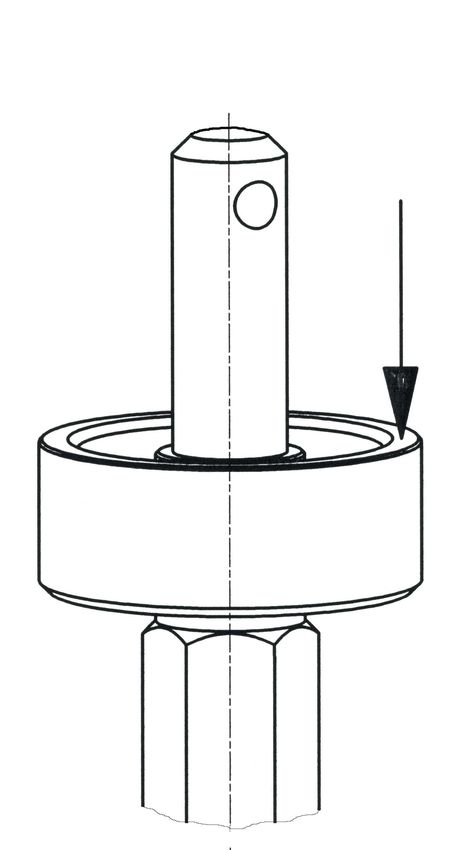
             Mounting position Any mounting position allowed except „cap pointing down“.

       Installation dimensions The actuators must be built in with a sufficient clearance to facilitate
                               the removal of the cap. (see figure below).

BA_PSL_AMS1x_0706_E.doc                                                                                  7
4. Operating principle
           Operating principle The linear actuators PSL-AMS are designed for the use as electric
                               valve actuators. Mounting to the valve is done via the actuator
                               pillars. Depending on the valve design, a lantern or a special
                               mounting plate will be required.

                                 The motor torque is transmitted via a multi-step spur gear to a
                                 trapezoidal thread spindle. The spindle itself converts the induced
                                 torque into an axial force via a spindle nut. The spindle nut‘s
                                 resulting linear vertical motion is self-locking and is transmitted via
                                 a coupling piece to the valve stem.

                                 During power failure and adjustment work the actuators
                                 can be emergency-operated via the hand wheel (see
                                 chapter 5/Manual Operation), except when using the
                                 fail-safe unit PSEP.

                                 5.      Manual Operation

             Manual operation A hand wheel is provided to operate the actuator in case of power
                              failure or for valve adjustment. If a fail-safe unit type PSEP (option)
                              is installed, this has to be disconnected to enable the actuator to be
                              operated by hand wheel. .

                                 At actuators of the series PSL201-204, PSL208-210 and PSL305-
                                 314 the hand wheel is tuning during motor operation. The actuators
                                 PSL320-325 are equipped with a declutchable hand wheel, that is
                                 standing still during motor operation. To operate these actuators
                                 manually, the knob at the top of the cover must be depressed and
                                 held down.
                                 Caution!
                                 The hand wheel should not be used in ongoing operation, as, the
                                 actuator tries to compensate the deviation in position, depending on
                                 the operating mode.
                                 PSL201-204      PSL208-210     PSL305-314        PSL320-325

                                 Manual operation

BA_PSL_AMS1x_0706_E.doc                                                                                    8
If a fail-safe device PSEP (option) is fitted to the actuator, this
                                has to be disconnected electrically to allow to drive the actuator
                                by hand wheel. Open the cover of the PSEP and disconnect the
                                cable from the minus terminal, see picture below. There is safety-
                                low voltage (24V) present.

                               6.      Mechanical Mounting

                               6.1.    Safety note

                   Safety note Beware of mechanical hazards due to electrically powered
                               actuator components!
                               With the actuator powered electrically, operating the unit holds
                               the danger of crushing your fingers, damaging the actuator
                               and/or the valve.

                                                                    Note: All mentioned items refer
                                                                    to the itemisation as shown on
                                                                    the page after page 24.

                                                                    During adjustment work, the
                                                                    actuator may be operated by
                                                                    means of the hand wheel only.
                                                                    Do not operate electrically!

BA_PSL_AMS1x_0706_E.doc                                                                               9
6.2.   Mounting to the valve

    How to mount the actuator
                                                               Unscrew the locking nut (item
                                                               10) from the spindle nut (item
                                                               9).

                                                               Check whether the coupling
                                                               piece (item 15) is drilled as per
                                                               the valve stem‘s end (item 11).
                                                               If necessary, re-machine.

                                                               Place the locking nut (item 10)
                                                               over the valve stem (item 11).

                                                               Place the disc springs (item 16)
                                                               over the valve stem.

                                                               Observe the various
                                                               arrangements for the disc
                                                               springs!
                                                               (see next figure).

BA_PSL_AMS1x_0706_E.doc                                                                         10
The arrangement of the disc
                                                              springs varies according to the
                                                              type of valve. There are three
                                                              versions:

                                                              A: Arrangement for two-way
                                                              valves with closing direction
                                                              „valve stem retracting“

                                                              B: Arrangement for two-way
                                                              valves with closing direction
                                                              „valve stem extending“

                                                              C: Arrangement for three-way
                                                              Valves

                                                              Screw the coupling piece (item
                                                              15) onto the valve stem, drill the
                                                              semi-drilled hole completely
                                                              through and secure with the pin
                                                              (item 14).

                                                              Insert the assembly of valve
                                                              stem, coupling piece and disc
                                                              springs into the spindle nut. Re-
                                                              adjust its position accordingly
                                                              with the hand wheel. Screw the
                                                              locking nut on and tighten it with
                                                              the wrench supplied with the
                                                              actuator.

                                                                     Introduce the pillars
                                                                     (item 12) into the bore
                                                                     holes at the valve
                                                                     bonnet and tighten them
                                                                     with the nut (item 13).

                          Before tightening the nut, both pillars must be fed completely into
                          the bore holes at the valve bonnet. If necessary, the spindle nut´s
                          position has to be adjusted with the hand wheel.
                          Non-observance may cause damage to the actuator!

BA_PSL_AMS1x_0706_E.doc                                                                         11
7.                              Electrical Connection
                                                                                       7.1.                             Safety Note

                                                 Safety note When performing electric work on this unit, the local accident
                                                             prevention regulations must be followed.
                                                             Observe EN 60204-1 (VDE 0113 part 1) to ensure human safety,
                                                             integrity of the assets as well as the proper functioning of the
                                                             unit.
                                                                                       Electric supply lines must be dimensioned for the peak current of
                                                                                       the unit and comply with IEC 227 and IEC 245. See relevant data
                                                                                       sheet.
                                                                                       Yellow-and-green coded cords may only be used for connection to
                                                                                       protective earth.
                                                                                       When leading wires through the cable glands on the actuator, their
                                                                                       minimum bending radius has to be considered.
                                                                                       The electric actuators PSL-AMS are not fitted with an internal
                                                                                       electric isolator, hence a switching device or circuit breaker must be
                                                                                       integrated in the facility. It should be installed close to the actuator
                                                                                       and should be easy to access for the user. It is important to mark
                                                                                       the circuit breaker as this actuator‘s isolator.

                                                                                       Electric installations and over-current protection devices must
                                                                                       conform to the standard IEC 364-4-41, protective class I.

                                                                                       7.2.                            Wiring Diagram

         Wiring Diagram Electric terminals are provided in a terminal box at the actuator.

        1 2 3               4               5             6     7               8          9 10 11 12 13 14 15 16 17 18 19 20 21 22 23                                                                                                                                                                                                       Taster
                                                                                                                                                                                                                                                                                                                                  RJ-45
                                                                                                                                                                                                                                                                                                                                   TTL
                                                                                                                                                                                                                                                                                                                                             Button
                                                                                                                                                                                                                              L/+ (siehe Typenschild/ see tag plate)
                                                                                                                                                                                                                                                                       N/- (siehe Typenschild/ see tag plate)
       + 0(2) - 10 V
       + 0(4) - 20 mA
       GND
                        + 0(2) - 10 V
                                        + 0(4) - 20 mA
                                                         GND

                                                               24 VDC
                                                               100 mA bei / at
                                                               max. Last / max. Load

                                                                                       L/+ AUF/ OPEN
                                                                                                       N/-
                                                                                                             L/+ ZU/ CLOSE
                                                                                                                             L/+ (24V AC/DC)
                                                                                                                             N/- (24V AC/DC)
                                                                                                                                               24 VDC / 100 mA
                                                                                                                                                                 + 0(2) - 10 V
                                                                                                                                                                 + 0(4) - 20 mA
                                                                                                                                                                 GND
                                                                                                                                                                                  (Option)
                                                                                                                                                                                             (Option)
                                                                                                                                                                                                        (Option)
                                                                                                                                                                                                                   (Option)

                                                                                                                                                                                                                                                                                                                PE

                                                                                                                                                                                                                                                                                                                     (Option)

                                                                                         24 V
                                                                                         AC/DC

                                                                                         115 V -
                                                                                         230 V
                                                                                         AC
                                                                                                                                                                                   Zu /                   Auf /
                       Aktive                                  Netz-                                                                           Ver-                               Closed                  Open                                          PC
        Sollwert-                Störmeldung        Binäre                                                                                                                                                                    Versorgungs- Feldbus-           Inbetrieb-
                     Positions-                               ausfall-                                                                         sor- Istwert    Wegschalter                                                                           Kommu-
        Eingang                   potentialfrei Ansteuerung                                                                                                                                                                    spannung Anschluß               nahme
                   rückmeldung                                 signal                                                                          gung            potentialfreier                                                                       nikation
                       Active                                   Fail                                                                                              Kontakt                                                       Power                  PC       Com-
                                                                                                                                                Supply

        Set value               Monitor relay Binary input                                                                                          Actual                                                                                 Fieldbus
                      position                                  safe                                                                                          Position switch                                                   supply               commu- missio-
          input                 potential-free     signals                                                                                          value                                                                                  interface
                     feedback                                  signal                                                                                          potential-free                                                   voltage              nication   ning
              Galvanisch getrennt / Galvanically isolated 1 kV                                                                                 Process-Sensor     contact
                                                                                                                                                                                                                                                                                                                                8013770 - S-217_E

                                                                  Wiring diagram

BA_PSL_AMS1x_0706_E.doc                                                                                                                                                                                                                                                                                                                             12
7.3.   Mains supply

           Mains supply                         Isolate the power supply.
                                                Safeguard the line against
                                                unauthorized and unintended
                                                restarting.

                                                Open the terminal box.

                                                The terminal box provides
                                                terminals to accommodate rigid
                                                and flexible cables of wire widths
                                                of 0.14 mm² to 2.5 mm² as well
                                                as a PE screw on the housing.

                                                Caution: Please observe the
                                                supply voltage and the maximum
                                                power consumption of the
                                                actuator as indicated on the
                                                actuator‘s tag plate!

                                                Connect supply and control lines
                                                to terminals (as indicated in the
                                                wiring diagram).

BA_PSL_AMS1x_0706_E.doc                                                         13
7.4.     Interfaces

                     Interfaces The actuator AMS11 has several interfaces inside the terminal box
                                which can be configured by the parameterising software PSCS or
                                by the control box PSC (see relevant manuals).

                                7.4.1. Communication Interface
                                For communication and parameterisation with a PC or a hand-held
                                device, connect the communication cable to the RJ45-connector
                                (item 4). Actuator parameters can be set using the software PSCS
                                or the control box PSC (see relevant manuals).

                                7.4.2.    Input Terminals

                                7.4.2.1. Galvanically isolated Set-Value

                                       1 2 3                        Terminals 1 through 3 are used
                                                                    to receive a parameterisable
                                                                    modulating set-value for control
                                                                    operation within the range of 0-
                                                                    20 mA or 0-10V.

                                7.4.2.2. Sensor Feedback for Process Controller
                                (optional)

                                                                    Terminals 15 through 17 are
                                       15 16 17                     used to receive a process
                                                                    sensor‘s feedback to the -
                                                                    optional - process controller, in
                                                                    the parameterisable range of 0-
                                                                    20 mA oder 0-10 V.

                                Caution!
                                The following binary inputs (7.4.2.3 & 7.4.2.4) have priority over the
                                modulating set-value. If the actuator is parameterised for
                                modulating service, these set-value settings are disregarded in the
                                case a binary signal is applied. Only after disconnection of the
                                binary signal the actuator will reposition according to the set-value
                                applied.

BA_PSL_AMS1x_0706_E.doc                                                                             14
7.4.2.3. Galvanically Isolated Binary Input

                                                         Terminals 9 through 11 are for
                                          9 10 11        binary open/close signals.
                                                         Standard voltage level is 24 V,
                                                         option is for 115/230 V; see
                                                         wiring plan. The actuator is then
                                                         driven in 3-point service.

                          7.4.2.4. Fail-safe port for Binary Input (optional)

                                                      The fail-safe port (terminals 12
                                             12 13    and 13) allows to drive the
                                                      actuator to a parameterised safety
                                                      position by applying a voltage of
                                                      24 V.

                          7.4.3. Output Terminals

                          7.4.3.1. Active Position Feedback
                                                      Terminals 4 through 6 are giving
                             4 5 6                    active position feedback,
                                                      parameterisable within the range
                                                      of 0-20mA or 0-10V. See also “9.1
                                                      Cut-off in end positions”!

                          7.4.3.2. Additional Position Switches (optional)
                                                    The activation points of the
                                                    optionally available position
                                        18 19 20 21 switches are freely adjustable via
                                                    cams. Terminals 18/19 and 20/21
                                                    provide potential-free opening or
                                                    closing contacts. The standard
                                                    switches are rated to 230VAC/5A.
                                                    Special switches with gold plated
                                                    contacts are available for low
                                                    power (up to 100 mA and 30V).

BA_PSL_AMS1x_0706_E.doc                                                                 15
7.4.3.3.    Voltage feed to Process Sensor (optional)
                                                        Terminals 14 and 17 provide an
                             14      17                 unregulated output voltage of 24
                                                        to 30 VAC at maximum 100 mA to
                                                        feed an external process sensor.

                          7.4.3.4.    Fault Indicating Relay (optional)

                                                        This potential-free normally-open
                                            7    8      relay contact (terminals 7 and 8)
                                                        allows to display parameterisable
                                                        fault indication to the control room.
                                                        See instruction manual for
                                                        software PSCS.

                          7.4.3.5.    Fieldbus Interface (optional)
                                                        Optionally a fieldbus interface can
                                                        be fitted to the AMS-actuator, with
                                                        wiring to a terminal block or an
                                                        external socket.
                                                        -> See special operating manual
                                                        for AMS-Fieldbus.

BA_PSL_AMS1x_0706_E.doc                                                                    16
7.5.    Accessories

                  Space Heater 7.5.1. Space Heater (optional)

                               Actuators PSL-AMS can be fitted with a space heater. When using
                               actuators in environments with high temperature fluctuations or
                               high humidity, we suggest a heating resistor be fitted to prevent the
                               build-up of condensation within the enclosure.

                                                                In actuators PS-AMS the space
                                                                heater is powered via the power
                                                                supply of the actuator, so it does
                                                                not have to be fed separately. For
                                                                retro-fitting the heating resistor,
                                                                wiring of the two cables has to be
                                                                made to the terminals on the main
                                                                board as per the picture on the
                                                                left.

                                                                Mounting of the space heater has
                                                                to be made to the indicated place
                                                                on the base plate by using the
                                                                screws provided. Route the cables
                                                                in a way to prevent them from
                                                                being squashed by the main
                                                                cover, and from being touched by
                                                                moving parts inside the actuator.

BA_PSL_AMS1x_0706_E.doc                                                                           17
7.5.2. Adjusting Additional Position Switches (optional)
           Position Switches   In PSL-AMS two switches for position feedback are available as
                               factory-mounted option.
                               They are either normally-closed or normally-open contacts, potential-
                               free. They are available with silver contacts (for currents between 10
                               mA and 5 A at maximum 230 V) or with gold-plated contacts (for
                               currents between 0,1 mA and 30 mA at maximum 30 V). Connection
                               goes to terminals 18/19 and 20/21.

                               The cams for closing the switches are located on the switch plate,
                               and are adjustable with a small screwdriver. Cam 1 is for retracting
                               the spindle nut, while cam 2 is for extending the spindle nut out of
                               the actuator.

BA_PSL_AMS1x_0706_E.doc                                                                          18
8.     Status display / Operating element

                          8.1.   LEDs inside terminal box

                                                     A red and a green LED on top of
                                                     each other (item 7) inside the
                                                     terminal box indicate the status of
                                                     the actuator.

                                                     A further single red LED
                                                     (optional) signals the status of the
                                                     optional fieldbus interface. -> See
                                                     special operating manual for
                                                     AMS-Fieldbus.

                          8.2.   Commissioning button

                                                     The commissioning button (item
                                                     6) for starting the automatic
                                                     commissioning run (to adjust the
                                                     actuator to the valve) is located
                                                     inside the terminal box, below the
                                                     communication port. -> See
                                                     chapter 9.1 “Cut-off in end
                                                     positions”

BA_PSL_AMS1x_0706_E.doc                                                                19
9.      Operation
                                  All internal parameters, like required motor torque, actual position,
                                  functional status, etc., are being permanently monitored during
                                  operation of the actuator PS-AMS. This ensures that the actuator
                                  positions with optimum accuracy, and closes the valve always tight.
                                  Deviations can be read out via communication software PSCS or
                                  via local control PSC.2 (see respective instruction manuals), or can
                                  be displayed to the control room using the optional fault indication
                                  relay. This provides maximum safety of the process.

                                  9.1.    Cut-off in End Positions

       Cut-off in End Positions Cut-offs of the PS-AMS actuators can be adjusted to meet the
                                valve function in an optimum way by using the communication
                                software PSCS (using a special interface cable, or optionally
                                Bluetooth connection). This will result in different behaviour of the
                                actuator. In case a position is surpassed or not reached, this can
                                be read out via the optional Fault Indication Relay or via the
                                communication software PSCS.

                                  9.1.1. Cut-Off by Force / Torque
                                  The actuator delivers the programmed maximum force / torque
                                  each time when driving to this end position. If the closing point
                                  inside the valve dislocates, e.g. when a seat gasket wears, then
                                  the actuator will drive further in its possible actuation range to try to
                                  reach the programmed force / torque.

                                  9.1.2. Cut-Off by Position automatically
                                  In normal operation, the actuator will stop at the position which was
                                  found at a mechanical stop in the valve or the actuator during
                                  Automatic Commissioning. If the closing point inside the valve
                                  dislocates, the actuator will NOT follow this dislocation but it will
                                  always stop at the point initially found.

                                  9.1.3. Cut-Off by Position
                                  In normal operation, the actuator will stop at the point which was
                                  defined by Manual Commissioning. This position is not depending
                                  on any mechanical stop inside valve or actuator.

BA_PSL_AMS1x_0706_E.doc                                                                                  20
10.     Commissioning

                                 The actuator is shipped in the „not commissioned“ condition with
                                 the green LED (item 7) flashing slowly. There will be no response
                                 to any input (set value or open/close signal). To make the actuator
                                 operational, it has to be commissioned to a valve.

                                 Depending on the type of cut-offs programmed (see 9.), there are
                                 two ways to do commissioning:
                                  - Automatic commissioning is done if at least one of the cut-offs is
                                 set to be “by force/torque” or “by position automatically”.
                                  - Manual commissioning has to be made in case both cut-offs are
                                 “by position”, either via software PSCS or via control box PSC.2.

                                 Caution!
                                 Electrical operation of the actuator is allowed only after mounting to
                                 a valve!

                                 10.1. Automatic commissioning

    Automatic commissioning This is performed if at least one of the cut-offs is set to be “by
                            force/torque” or “by position automatically”.
                                 During automatic commissioning the actuator goes through the full
                                 programmed valve stroke / angle automatically. Parameters
                                 specific to the valve are being measured and calculated values are
                                 permanently stored in the actuator. At the same, set value and
                                 position feedback range are scaled.
                                 To enable Automatic Commissioning, a mechanical stop is required
                                 in at least one end position (usually the closed position) of the
                                 valve. This mechanical stop can be either given by design of the
                                 valve, or it may be adjusted by the stop screws of the actuator (only
                                 when cut-off “by position automatically“ is programmed).
                                 .

BA_PSL_AMS1x_0706_E.doc                                                                              21
Procedure:
                                                            a.) Mount the actuator to a valve,
                                                                wire it and switch the power
                                                                on, according to these
                                                                instructions. Press the button
                                                                (item 6) inside the terminal
                                                                box for at least 3 seconds.

                                                            b.) The automatic
                                                                commissioning run starts and
                                                                the actuator moves through
                                                                the whole valve stroke. The
                                                                green LED flashes quickly
                                                                during this commissioning
                                                                run.

                                                            c.) After finishing the automatic
                                                                commissioning, the actuator
                                                                is ready for use. The green
                                                                LED is glowing permanently.

                          Note
                          If the actuator is stalled during the automatic commissioning run
                          BEFORE reaching a desired position-dependent cut-off, it will then
                          store the so-obtained stroke.

                          Note
                          If, as a result of automatic commissioning, no force/torque limit is
                          found, or if a stroke below the minimum allowed stroke (5 mm in
                          standard version) is found, the commissioning run will be aborted.
                          The actuator returns to the “not commissioned” condition (i.e. green
                          LED flashing slowly), even if the actuator had been initialized
                          correctly before that.

                          Note
                          Automatic commissioning can be started via software PSCS or via
                          control box PSC as well. -> See relevant operation manuals

                          Caution!
                          If the LEDs display other types of signals than “flashing green” or
                          “glowing green permanently”, please refer to the chapter on “Fault
                          messages”.

                          Caution!
                          The mains supply must not be interrupted during the
                          commissioning run!

BA_PSL_AMS1x_0706_E.doc                                                                     22
10.2. Manual commissioning

  Manual commissioning If both cut-offs are selected to be „by position“, the actuator must be
                               commissioned manually using the software PSCS or the control box
                               PSC.

                               Procedure:

                                                                 a.) Mount the actuator to a valve,
                                                                     wire it and switch the power
                                                                     on, according to these
                                                                     instructions. Permanently
                                                                     apply the set-value for the
                                                                     closed position, or the input
                                                                     signal „close“.

                               Caution!
                               The valve stroke has to be parameterised using software PSCS or
                               control box PSC! -> See relevant manuals.

                                                                 b.) Drive the actuator to the
                                                                     closed position of the valve
                                                                     using software PSCS or
                                                                     control box PSC. The open
                                                                     position of the valve will be
                                                                     calculated in accordance with
                                                                     the programmed valve stroke.

                                                                 c.) After manual commissioning,
                                                                     the actuator is ready for use.
                                                                     The green LED is glowing
                                                                     permanently.

                               Note
                               If the parameterised valve stroke, starting from the adjusted closed
                               position, exceeds the possible actuator stroke, then the operating
                               stroke will be reduced to the resulting maximum possible value.

BA_PSL_AMS1x_0706_E.doc                                                                           23
11.     Status messages

                               11.1. Fault indicator relay
      Fault indicator relay Fault messages can be transmitted to control boards with a
                               maximum load of 24 VDC/100 mA via an optionally available closing
                               contact at terminals 7 and 8. The messages can be parameterised
                               via software PSCS or control box PSC. -> See relevant manuals

                               11.2. Tracing faults
                               See the table on page 25 for explanation of the blinking codes of the
                               status-LEDs.

                               12.     Maintenance and repair

                               Under the conditions of use as per specification as lined out in the
                               data sheet, the PS-AMS actuators are free of maintenance. All
                               gears are lubricated for their service life and do not require to be re-
                               lubricated.

                     Cleaning Clean the actuators with a dry soft cloth and do not use any
                              cleaning agent. Do not use any coarse or abrasive materials.

                               13.     Safety on Transportation

                               For transportation and storage all cable glands and connection
                               flanges have to be closed to prevent ingress of moisture and dirt. A
                               suitable method of packaging is required for transporting to avoid
                               damage of coating and any external parts of the actuator.

                               14.     CE - Declaration of Conformity

                               See page 26

BA_PSL_AMS1x_0706_E.doc                                                                              24
11.2. Tracing Faults

BA_PSL_AMS1x_0706_E.doc   25
Declaration of Conformity
We,
PS Automation GmbH
Philipp-Krämer-Ring 13
D-67098 Bad Dürkheim
Germany

declare under our sole responsibility that we are manufacturing the electrical
actuators of series

PSL...; PSQ...; PSR...; PSL-AMS...; PSQ-AMS...

according to the follwing EEC regulations:

89/336/EEC                       Electro-magnetical Compatibility

73/23/EEC                        Low Voltage Directive

and that we have successfully tested them as per the following harmonized
standards:

EN 61000-6-2: 2001               Electro-magnetical compatibility (EMC), Generic standards
                                 Immunity for industrial environments

EN 61000-6-4: 2001               Electro-magnetical compatibility (EMC), Generic standards
                                 Emission standard for industrial environments
EN 61010-1: 1995                 Safety Requirements for Electrical Equipment for
                                 Measurement, Control and Laboratory use

Bad Dürkheim,             2004

Max Schmidhuber
(General Manager)

                                           CAUTION!
To ensure compliance of these actuators with the above directives, it is the responsibility of
the specifier, purchaser, installer and user to observe the relevant specifications and
limitations when taking the product into service. Details are available on request, and are
mentioned in the Installation and Maintenance Instructions.

BA_PSL_AMS1x_0706_E.doc                                                                          26
15.    Vertretungen / Representatives
                          Italy                            China
                          G.E.I. s.r.l.                    SHENZHEN MAXONIC
                          Via Pennella, 94                 AUTOMATION
                          I-38057 Pergine Valsugana        Control Co Ltd.
                          (TN)                             7th Floor, Block 7, Tian An
                          Tel.:  04 61-53 25 52       Industrial Estate
                          Fax:  04 61-53 31 17        Nanyou, Shenzhen, Guangdong
                          eMail: GEI@dnet.it               P. R. CHINA
                                                           Tel.:  7 55 26 52 18 78
                                                           Fax:  7 55 26 05 28 00
                                                           eMail:
                          Spain                            szmaxoni@public.szptt.net.cn
                          SERTEMO, S.L.
                          Pol. Ind. Alba - Avda.
                          Generalitat 15
                          Apartado de Correos, 142         Hong Kong
                          E-43480 Vila-Seca (Tarragona)    PS-MAXONIC Hong Kong Ltd.
                          Tel.:  977-39 11 09         Room 803-4, Yale Industrial
                          Fax:  977-39 44 80          Centre
                          eMail: sertemo@sertemo.com       61-63 Au Pui Wan Street
                          www.sertemo.com                  Fotan, Shatin, Hong Kong
                                                           Tel.:  26 87-50 00
                                                           Fax:  81 01-37 43
                                                           eMail: simon@maxonicauto.com
                          Denmark                          www.maxonicauto.com
                          Gustaf Fagerberg A/S
                          Kornmarksvej 8-10
                          DK-2605 Brøndby                  Singapore
                          Tel.:  (0) 43 29 02 00      BEAVER CONTROMATIC
                          Fax:  (0) 43 29 02 02       30 Shaw Road #02-02 to 06
                          eMail: jo@fagerberg.dk           SGP-Singapore 367957
                          www.fagerberg.dk                 Tel.:  67 46 96 77
                                                           Fax:  67 43 11 94
                                                           eMail: bcvalves@pacific.net.sg
                          Netherlands, Belgium             www.beavercontro.com
                          AMAL Automation B.V.
                          De Dijken 5.A
                          NL-1747 EE Tuitjenhorn
                                                           Great Britain
                          Tel.:  (0) 22-4 55 23 16
                                                           IMTEX Controls Ltd.
                          Fax:  (0) 22-4 55 23 17
                                                           Unit 5A, Valley Industries,
                          eMail: info@omal.nl
                                                           Hadlow Road
                                                           GB-Tonbridge, Kent TN11 0AH
                                                           Tel.:  (0) 17 32-85 03 60
                                                           Fax:  (0) 17 32-85 21 33
                                                           eMail: sales@imtex-controls.com
                                                           www.imtex-controls.com

                          PS Automation GmbH
                                                           Tel.:    (0) 63 22-60 03-0
                          Gesellschaft für Antriebstechnik Fax:     (0) 63 22-60 03-20
                          Philipp-Krämer-Ring 13
                                                           e-mail: Info@ps-automation.com
                          D-67098 Bad Dürkheim             Internet: http://www.ps-automation.com

BA_PSL_AMS1x_0706_E.doc                                                                      27
BA_PSL_AMS1x_0706_E.doc   28
You can also read