Infl uence of Position Measurement on Accuracy in 5-Axis Machining
←
→
Page content transcription
If your browser does not render page correctly, please read the page content below
Technical Information

Influence of Position Measurement on Accuracy
in 5-Axis Machining
Productivity and accuracy are important attributes in the competition for machine tools. Five-axis machining provides considerable poten-
tial for increasing productivity. In many cases it permits higher metal removal rates than 3-axis machining. Production times can be signifi-
cantly shortened thanks to a reduction of time required for resetting, for example, or through multi-operation machining in one setup. In
any case, with increasingly complex workpiece geometry, 5-axis machining is becoming an indispensable part of the machining process.

Since significantly larger traverse ranges of linear axes are usually required for 5-axis machining, machines need to provide high accuracy
over the entire working space. Moreover, the two rotary axes in a 5-axis machine tool can greatly influence attainable workpiece accura-
cy. Besides the rotary axes, in most cases the linear axes must also be moved in order to change the orientation of the cutter to the
workpiece surface. This can cause visible flaws in the traverse range of up to five axes within a small area of the workpiece surface. In
5-axis machining, precision-limiting effects in the drives, such as screw-pitch and transmission error, reversal error or thermally induced
displacement can therefore much more quickly lead to the production of scrap. The positioning accuracy of linear and rotary axes play a
decisive role here in the performance of a 5-axis machine tool.

By now, 5-axis machining has become in-
dispensable in many areas of metal-cutting
machining. Clear economic advantages re-
sult from the capability to machine work-
pieces completely in one setup: the door-
to-door time of a part can be dramatically
reduced. At the same time, part accuracy
can be significantly increased.

Beyond this, the additional rotary axes al-
low better access to complex workpiece
contours, for example cavities in dies or
molds.Often, they permit shorter tools with
less inclination to chattering so that even
higher metal removal rates are achieved.

With 5-axis simultaneous machining, the
cutting speed at the tool tooth can be held
within narrow limits even on complex con-
tours. This brings significant benefits with
regard to the attainable surface quality.
What is more, the use of highly productive
tools (e.g. toroid cutters) when milling free-
form contours would not be possible at all
without 5-axis simultaneous machining.

September 2011
Fields of Application for 5-Axis Machining
Parts for Aeronautics and Space 5-axis machining in automobile manu- Five-axis machining in the field of medi-
Industry facturing cal technology
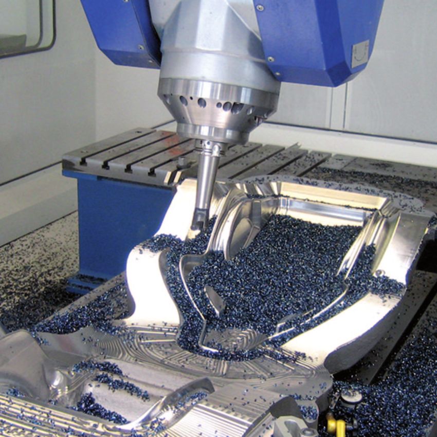
High strength and low weight are essential Uncounted molds and dies are needed in In the field of medical technology, demand
for the aeronautics and space industry. In- automobile manufacturing for sheet metal is high for devices that are adapted to spe-
tegral construction has established itself as and plastic processing. Dies for sheet met- cial examinations or therapies. This can
the way to minimize the weight of “air- al forming can be up to 6 m long and need make treatments considerably more pre-
borne” parts: components with complex to be milled at the very high accuracy of cise and reduce aftereffects on the pa-
structure are manufactured completely ± 0.02 mm so that the upper and bottom tients. The devices are often characterized
from a single blank. Metal removal levels dies can work together with the correct by very complex geometries that make
can be as high as 95 %. This high “buy-to- gap. Moreover, a very high surface quality 5-axis machining of single parts on milling
fly” rate leads to high costs for the raw of all functional surfaces is necessary in or- machines attractive.
material of the blanks. der to ensure that the forming tools have a
long service life. Increasing life expectancy brings with it an
In the area of structural components, 5-axis increase in demand for tooth and joint im-
machining opens new opportunities for re- plants. Today, hip and knee replacements
ducing weight without loss of component offer many people the opportunity for a sig-
strength. First, a computer-aided topology nificantly better quality of life. In their exter-
optimization is conducted that adapts the nal form, tooth and joint implants have to
geometry of the component to the respec- be perfectly fitted to the specific mating
tive loads. The result: the material is surfaces of a human body. Implants are
brought specifically to where the mechani- mostly manufactured on milling machines,
cal load can be highest. In the other areas, because milling makes even small batch
material is specifically reduced. For exam- sizes possible. Due to complex shaping of
ple, the thickness of walls for stiffening can implants, medical technology is one of the
be easily adapted to the load distribution in largest fields of application for 5-axis ma-
the component. The wall thickness can de- chining. A prerequisite for the economical
crease with increasing height, for example. manufacturing of such sophisticated com-
This workpiece geometry can be realized in ponents is machines with high-accuracy
a simple way through 5-axis pocket milling. position measurement for accurate and
precise feed movements.
When manufacturing the tool contour, the
machine has to maintain a very small dis-
tance between cutting paths in order to ful-
fill the requirements for high surface quali-
ty. This automatically lengthens the run
times of the NC programs. The required ac-
curacy of the forming tools is a formidable
challenge for machine tools: high accuracy
during long program run times on large
components necessitates high thermal sta-
bility of the machine structure and the feed
drives.
Five-axis machining has long become the Five-axis machining opens new perspec-
standard for the machining of jet engines. tives for shortening machining times be-
High efficiency requirements are driving cause even deeply curved contours of
continuous improvements in the flow char- forming tools become more easily accessi-
acteristics of all jet engine components. The ble. In addition, special tools such as toroid
resulting component geometries are very or radius cutters can be used that permit
complex and are therefore manufactured significantly larger path spacing and there-
exclusively in 5-axis simultaneous milling fore reduce program run times.
movements.
2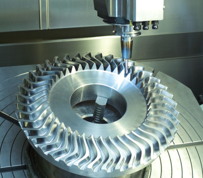
Requirements of Position Measurement

In 3 axis milling, the feed axes move within
the dimensions of the workpiece plus the
tool diameter. Unlike with 3-axis machining,
in 5-axis machining the inclination of the
tool can be adjusted with respect to the
workpiece surface. If the position of the
tool center point (TCP) remains unchanged,
a change in the cutter orientation usually
requires additional movement in the linear
axes. These compensating movements
necessarily increase the traverse range re-
quired by the linear axes. Because increas-
ing traverse range also means increased
positioning error, feed axes of 5-axis ma-
chines need significantly higher accuracy
and reproducibility .

The compensating movements of the lin-
ear axes are superimposed on the move-
ments of the tool center commanded by
the NC program in X, Y and Z. Due to this
superimposition, the axis feed rates for the
tool center can significantly exceed the
programmed feed rate. The increase in
feed velocity results in increased heat gen-
eration in the motors, transmission and re-
circulating ball screw. Depending on the
principle of position measurement, the
generation of heat can cause significant
position error. To prevent faulty workpieces,
precise position measurement in the feed
axes directly at the moving machine ele-
ments is imperative.

                                 B

                                 A
                                 A

             A: Traverse range with 3-axis machining
             B: Traverse range with 5-axis machining,
                incl. compensating movements

                                                        3
Position acquisition on linear axes             As an alternative to using a recirculating      the same time quiet operation, linear mo-
The position of a feed axis can be mea-         ball screw, linear feed axes can also be        tors already depend on high-resolution, ac-
sured either through the recirculating ball     driven by linear motors. In this case, the      curate linear encoders. For this type of
screw in combination with a rotary encod-       position of the machine axis is also mea-       drive, the advantages of Closed Loop oper-
er, or through a linear encoder. If the axis    sured directly by a linear encoder mounted      ation apply unrestrictedly.
position is determined from the pitch of the    on the axis slide. For highly dynamic and at
feed screw and a rotary encoder (see top il-
lustration), then the ball screw must per-
form two tasks: As the drive system, it
must transfer large forces, but as the mea-
suring device it is expected to provide a
highly accurate screw pitch. However, the
position control loop only includes the rota-
ry encoder. Because changes in the driving
mechanics due to wear or temperature
cannot be compensated in this way, this is
called operating in a Semi-Closed Loop.
Positioning errors of the drives become un-
avoidable and can have a considerable in-
fluence on the quality of workpieces.

If a linear encoder is used for measure-
ment of the slide position (middle illustra-
tion), the position control loop includes the
complete feed mechanics. This is referred
                                                Semi-Closed Loop: Position measurement of a linear axis by a rotary encoder in the feed motor
to as Closed Loop operation. Play and in-
accuracies in the transfer elements of the
machine have no influence on position
measurement. This means that the accura-
cy of the measurement depends almost
solely on the precision and location of the
linear encoder.

Various conditions of application together
with growing feed rates and forces lead to
constant changes in the ball screw’s ther-
mal condition. Local temperature zones de-
velop on a recirculating ball screw, which
change with every change in position and
decisively reduce accuracy in the Semi-
Closed Loop.

High reproducibility and accuracy over the
entire traverse range of linear axes can
therefore be achieved only through opera-
tion in a Closed Loop. The results are pre-     Closed Loop: Position measurement of a linear axis by a linear encoder
cise workpieces and a drastically reduced
rejection rate.

                                                Thermographic image of a recirculating ball screw with increased temperature
4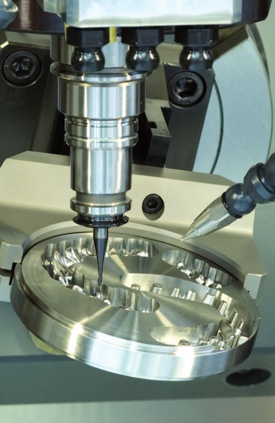
Position acquisition on rotary axes               The rotary axes that are driven directly by a   transmission. Rotary axes with torque mo-
The basic principle for linear axes also ap-      torque motor play a special role. The           tors require a high-resolution angle encoder
plies to rotary axes. Here, too, the position     torque motors’ special design permits very      immediately on the machine axis. They are
can be measured with a rotary encoder on          high torque without additional mechanical       always operated in a Closed Loop.
the motor, or with a high-accuracy angle
encoder on the machine axis.

If the axis position is measured using a ro-
tary encoder on the feed motor it, too, is
referred to as a Semi-Closed Loop, be-
cause the transmission error of the gear
mechanisms cannot be compensated
through a closed position loop.

Error of the mechanical transmission in ro-
tary axes are caused by
• eccentricity of the gear wheels,
• play, or
• friction and elastic deformations in the
  tooth contacts and the bearings of the
  transmission shafts.
Beyond this, most prestressed transmis-
sions are subject to significant friction that
heats the rotary axes and can therefore—          Semi-Closed Loop: Position measurement by rotary encoder on the feed motor.
depending on the mechanical design—re-            Errors of the drive mechanism are not recognized.
sult in positioning error.

In a Semi-Closed Loop, the error in the
transmission of rotary axes leads to sub-
stantial positioning error and to significantly
reduced repeatability. The errors of the ro-
tary axes are transferred to the geometry
of the workpiece, which can greatly in-
crease the number of rejected parts.

The positioning accuracy and repeatability of
rotary axes can be decidedly improved with
the use of precise angle encoders. Since
the axis positions are no longer measured
on the motor, but rather directly on the rota-
ry axes of the machine, this is referred to as
Closed Loop operation. Errors of rotary axis
transmissions have no influence here on po-
sitioning accuracy. The accuracy with which       Closed Loop: Position measurement by an angle encoder on the machine axis.
a rotary axis can move to a certain axis posi-    Errors of the drive mechanism are compensated.
tion over a long period is also decidedly
increased. Economic manufacturing with
minimal scrap is the result.

                                                  Torque motor: Rotary axes with torque motors are operated in a Closed Loop.

                                                                                                                                            5
Machining Examples
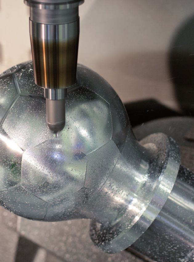
Five-Axis Simultaneous Machining with Very High Precision
Telstar soccer ball
The soccer ball for the FIFA World Champion-
ships of 1970 and 1974 were named after the
Telstar, the first non-military communication
satellite, which was launched into space by
the NASA and AT&T in 1963. The Telstar ball
bears over 20 white hexagonally and 12 black
pentagonal pieces that were sewn together.
This ball serves as the model for a work-
piece that can be milled on a 5-axis ma-
chine tool. The resulting workpiece is being
used as a test piece to prove machining ac-
curacy with 5-axis milling.
The Telstar workpiece was manufactured in
three machining steps on the basis of pre-
turned blanks:
• Three-axis milling of the pentagons with
vertical paths and inclined cutter
• Three-axis milling of the hexagons with
horizontal paths and inclined cutter
• Five-axis milling of the seams
A perfect optical appearance of the Telstar
workpiece is possible only if the “seams”
between the pentagons and hexagons are
milled with consistently superb precision
despite a machining time of over two
hours.
Five-axis manufacturing of the Telstar World Championship ball of
1970 and 1974
Machining sequence for 5-axis machining of the Telstar workpiece
Milling the pentagons: Milling the hexagons: Milling the seams:
3-axes, inclined cutter 3-axes, inclined cutter Five axes simultaneously
Climb milling Climb milling
Machining time: 22 minutes Machining time: 2 h 17 min Machining time: 11 minutes
Feed rate: 6 m/min Feed rate: 6 m/min Feed rate: 0.4 m/min
Cutter: Ø = 16 mm Cutter: Ø = 16 mm Cutter: Ø = 25 mm
Line spacing: 1.5 mm Line spacing: 0.2 mm Inclination angle: 55°
Inclination angle: 40° Inclination angle: 40°
6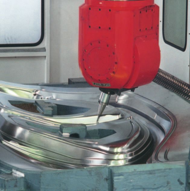
At the intersections, exactly three seams
meet that are milled with various cutter in-
clinations. An intersection can therefore be
machined precisely only if the cutter’s tool
center point (TCP) is positioned with three
differing inclinations at exactly the same
point.

However, the three inclination angles of the
cutter require large compensation move-
ments in the linear axes. For each seam, a
much different position of the linear and ro-
tary axes results at the TCP position of an
intersection.

During milling, positioning errors in one or
more feed axes inevitably prevent the TCP
positions from coinciding when milling the
three seams at their intersection. High ac-
                                                  Semi-Closed Loop: influences of the drive mechanics impair
curacy in the positioning of all feed drives is
                                                  machining accuracy. The seam width varies. The seam intersections
indispensable for precise machining of the
                                                  are visibly inaccurate.
seams, including the intersections.

For a simple visual evaluation of the Telstar
workpiece’s accuracy, a 0.15 mm deep
seam is manufactured throughout with a
25 mm diameter cutter. This results in a
very flat seam cross section, so that even
the smallest error in the seam’s depth
(±10 µm and less) causes clear fluctuations
of the seam width.

If the Telstar workpiece is manufactured on
a machine in a Semi-Closed Loop, the po-
sitioning accuracy and repeatability is limit-
ed by the transmission error of the recircu-
lating ball-screw in the linear axes and the
transmission in the rotary axes. The result:
the seam width fluctuates on the Telstar
workpiece. The intersections cannot coin-
cide exactly with each seam, so that a clear
displacement of the seams’ centers re-
sults.

In a Closed Loop, the feed axes attain very       Closed Loop: Thanks to the precise linear and angle encoders
high positioning accuracy and repeatability       from HEIDENHAIN, errors in the drive mechanics have no
over the entire traverse range. This makes        influence on the result of machining. The seams are milled to
precise machining of neighboring sections         the correct width, and the intersections all match up exactly.
on the workpiece possible, even with large
changes to the cutter orientation and sub-
stantial periods between the individual ma-
chining steps. The attainable precision is
visible in the intersections of the seam
paths. Each intersection is approached in all
three neighboring seams. In addition, the
seam width remains constant over the en-
tire circumference of the Telstar workpiece.

                                                                                                                   7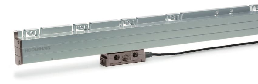
Five-Axis Simultaneous Plain Milling

Polygonal workpiece                              To examine the effect of position measure-              The illustrations below show the effect of
Five-axis machining provides considerable        ment on the result of machining, workpiec-              eccentricity in a gear stage. The transmis-
potential for reducing machining times. The      es were machined with the B axis sepa-                  sion with precisely assembled gears trans-
lateral surface of a polygonal workpiece is      rately in a Closed Loop and in a                        fers the motion of the drive motor without
finished simultaneously with a plain milling     Semi-Closed Loop. All other axes were in a              error to the tilting axis. If a transmission
cutter in five axes in one revolution of the     permanent Closed Loop.                                  gear wheel is eccentric, the movement of
workpiece. Compared with 3-axis machin-                                                                  the tilting axis has a sinusoidal error.
ing of the lateral surface with a ball-nose      In a Semi-Closed Loop, mechanical errors
cutter, 5-axis machining reduces machining       of rotary axes can cause position errors                The illustrated polygonal workpiece was
time to 30 %.                                    and therefore result in inaccuracy. Tilting             manufactured on a milling machine whose
                                                 axes often have drives with multiple-stage              tilting axis has a transmission reduction of
Precise machining with five simultaneous-        gearing. For uniform motion in a tilting axis,          i = 120. The motor pinion has a diameter of
ly moving feed axes place stringent re-          all gear components must have high manu-                40 mm. The radial runout of the pinion is
quirements on the accuracy of the feed           facturing accuracy and be assembled pre-                ± 0.058 mm.
drives. Depending on the type of position        cisely. Even small eccentricity errors of the
measurement, the errors of the additional-       gear can cause distinct fluctuations in the
ly required rotary and tilting axes can          speed of the tilting axis.
cause significant limitations on workpiece
quality. It is therefore essential to pay spe-
cial attention to the correct encoder and its
integration into the control loop.

The periphery of the polygonal workpiece
is machined in one revolution of the C axis
with simultaneously interpolated move-
ment of the B axis. During machining of                                                                  i=1
the lateral surface, the B axis is tilted in
and out five times in a tilting range be-                                                  Drive                      Movement of the
tween 1° and 19°.                                                                          motion                     tilting axis

                                                                                                                                Error-free transmission
                                                                                 movement

                                                                                                                                Transmission with an
                                                                                                                                eccentricity error
                                                                                 Actual

                                                                                                                        Ideal movement
                                                                                               360°

                                                                         Position errors on rotary axes due to eccentricity in the
                                                                         transmission, gear reduction i = 1

                                                                                                           i = 120

                                                                                      Drive                                       Movement of
                                                                                      motion                                      the tilting axis

                                                                                                                  10”
                                                                                                                                Error-free transmission
                                                                                movement

                                                                                                                                Transmission with an
                                                                                                                                eccentricity error
                                                                                Actual

                                                                                                    3°

                                                                                                                     Ideal movement

                                                                         Position errors on rotary axes due to eccentricity in the
                                                                         transmission, gear reduction i = 120
8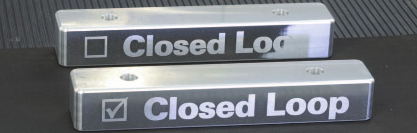
If the tilting axis is controlled in a Semi-                         In a second experiment, the tilting axis
Closed Loop, the sinusoidal position error                           was controlled in a Closed Loop. Here a
generated by the transmission cannot be                              HEIDENHAIN angle encoder with optical
detected by the drive controller. One revo-                          scanning was employed. The angle encod-
lution of the drive motor with eccentric pin-                        er measures the axis position directly at
ion causes motion errors of the tilting axis                         the tilting axis. In this way the effect of the
in the range of ± 10 angular seconds. The                            transmission error from the gears is imme-
error repeats itself every 3° with respect to                        diately detected. The drive controller reacts
the tilting angle.                                                   immediately to very small deviations and
                                                                     generates the equivalent countermove-
In a first experiment, the polygonal work-                           ment of the feed motor. The transmission
piece is machined in the Semi-Closed                                 errors therefore have no effect on the re-
Loop. The position errors generated by the                           sult of machining.
transmission are clearly visible as surface
ripple on the lateral surface of the polygo-                         Thanks to the HEIDENHAIN angle encod-
nal workpiece. The resulting form deviation                          ers on the rotary axes, the lateral surface
is ± 0.015 mm. The transmission error is                             can be milled in five axes simultaneously
visible only on the sections of the work-                            with short machining time and, at the same
piece at which the tilting axis moves.                               time, high surface quality and accuracy.

Semi-Closed Loop: Polygonal workpiece with surface error.            Closed Loop: Polygonal workpiece with very high surface definition.

                                                      B-axis tilts

                                                       B axis is
                                                       stopped

Machining a polygonal workpiece with plain milling and rotary and
tilting axes
                                                                                                                                           9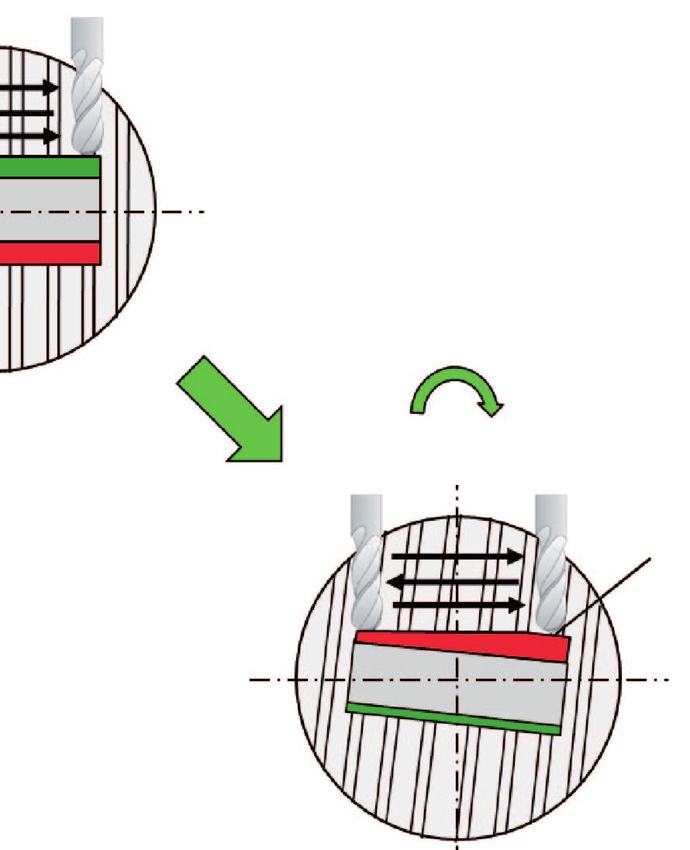
Machining in Opposite Orientations

Requirements for the accuracy of                Positioning errors can occur on rotary axes          To illustrate the influence of positioning ac-
rotary axes                                     when the machining position is measured              curacy in rotary tables on machining in op-
The sides of prismatic components are of-       at the shaft of the drive motor (Semi-               posite orientations, a text was carved out
ten machined in opposite orientations. In       Closed Loop), because the errors in the ro-          of the sides of a cuboid component. First
this case, one side is machined first—per-      tary axis transmission (play, elasticity, radial     the component is probed on a 5-axis mill-
haps by using a tilting axis to incline the     runout of the gear shaft) cannot be includ-          ing machine on one of the workpiece sides
workpiece with respect to the tool. The         ed in the position control and are not com-          in the tilted plane. Then a text is cut out
workpiece is then turned 180° by a rotary       pensated. Depending on the design of the             with a ball-nose cutter and 3-axis interpolat-
table to machine the opposite side.             drive mechanics, Semi-Closed Loop control            ed climb milling and up-cut milling. The
                                                can result in positioning error in the turn-         characters have a height of 0.025 mm.
Machining in opposite orientations places       about movement of ± 10 millidegrees and              Then the component is turned around on
stringent demands on the positioning accu-      more.                                                the rotary table by 180° in order to carve
racy of the rotary table. Even small angular                                                         out a second text with the same character
errors in the turnabout movement result in      The accuracy of a rotary table can be dra-           height on the opposite side.
errors in the parallelism of opposite sides     matically improved by using precise angle
of the workpiece. On a workpiece with a         encoders that measure worktable move-
500 mm edge length clamped at the cen-          ments directly. The transmission error in
ter of a rotary table, a positioning error of   the gears of rotary tables are ascertained
only two millidegrees results in an error of    by the angle encoder and therefore com-
0.01 mm perpendicular to the surface.           pensated in the position control (Closed
                                                Loop). In Closed Loop operation, the preci-
                                                sion of the angle encoder largely decides
                                                the accuracy of the turnabout movement.
                                                Angle encoders with optical scanning can
                                                make values of less than 0.3 millidegree
                                                possible.

                            180°
                                                                                                                180°

                                                                                                                                     Cutter not
                                                                                                                                     engaged

        Engraving                                                                        Engraving
        depth                                                                            depth

        constant                                                                         variable

            Closed Loop                                                                    Semi-Closed Loop
            Precise positioning, contour                                                   Positioning error leads to contour dam-
            is machined precisely                                                          age on the workpiece

10
First a workpiece is milled in a Closed are recognizable: on the back of the compo-
Loop (see 9 on the workpiece). Then, a nent milled in a Semi-Closed Loop the en-
second workpiece is machined on the graving is deeper at left while at right the tool
same machine in a Semi-Closed Loop is simply cutting air.
(see on the workpiece). The difference Position-dependent and direction-dependent
becomes apparent very soon. While the positioning errors in the Semi-Closed Loop
texts milled in Closed Loop control with cause a slant in the machine table and work-
precise linear and angle encoders were piece. This results in a plainly flawed engrav-
machined without error on both sides, in ing and the rejection of the workpiece.
the Semi-Closed Loop, machining errors
Semi-Closed Loop: Influences on the drive mechanism Closed Loop: Accuracy-limiting influences from the drive mechan-
(e.g. transmission errors) can impair the machine’s accuracy and ics have no influence on the results of machining. Thanks to the
therefore the machining accuracy and surface quality. precise angle encoders from HEIDENHAIN, a high contour accura-
cy and excellent surface definition of the workpiece are achieved.
11Encoders
Five-axis machining places particularly de-
manding requirements on the accuracy of
feed drives because the traverse ranges
and axis feed rate grow in comparison with
3-axis machining. The generation of heat
and mechanical transmission error in the
feed drives turn position measurement of
the feed drives into a decisive factor for
machining precision. Scrap and costs are
minimized with the correct position acquisi-
tion.
Therefore, linear encoders for linear axes
as well as angle encoders for rotary and
tilting axes are indispensable for machine
tools on which high positioning accuracy
and a high machining speed are essential.
Because linear and angle encoders from
HEIDENHAIN ascertain the movement of
the axis directly and immediately. Mechani-
cal transfer elements therefore have no in-
fluence on position measurement—kine-
matics errors, thermal errors and
influences of forces are measured by the
encoder and taken into account in the posi-
tion control loop. This makes it possible to
eliminate a number of potential error sources:
For linear axes:
• Positioning error due to thermal behavior
of the recirculating ball screw
• Reversal error
• Errors due to deformation of the drive
mechanics by machining forces
• Kinematics errors through pitch error in
the recirculating ball screw
For swivel, tilting and rotary axes:
• Mechanical transmission errors
• Reversal error
• Errors due to deformation of the drive
mechanics by machining forces
For more information
• Catalog: Linear Encoders for Numeri-
DR. JOHANNES HEIDENHAIN GmbH cally Controlled Machine Tools
Dr.-Johannes-Heidenhain-Straße 5 • Catalog: Angle Encoders
83301 Traunreut, Germany • Catalog: Angle Encoders without
{ +49 8669 31-0 Integral Bearing
| +49 8669 5061
E-mail: info@heidenhain.de
www.heidenhain.de
895 283 · 00 · A · 02 · 9/2011 · PDFYou can also read