UPGRADE OF THE CRYOGENIC SYSTEMS OF WENDELSTEIN 7-X - MPG.PURE
←
→
Page content transcription
If your browser does not render page correctly, please read the page content below
TPS12405.R1 1
Upgrade of the cryogenic systems of
Wendelstein 7-X
Thomas Rummel, Michael Nagel, Michael Pietsch, Sylvio Raatz, C. P. Dhard, Andreas Braatz, Marko
Ihrke, Hans-Stephan Bosch, and the W7-X team
steady-state plasma operation. Details about the W7-X cryo
Abstract—The Wendelstein 7-X experimental device has vacuum pumps can be found in [5].
completed the third plasma operation campaign in November Consequently, the cryogenic system has to be upgraded to
2018. The running, two year shut down phase is being used to supply the new components. These measures are described in
install new diagnostics, new in-vessel-components (steady-state
chapter III.
divertor and cryo pumps) and their auxiliary supply systems.
Especially the installation of the ten cryo pumps requires a Another motivation for an upgrade is an important lesson
substantial upgrade of the cryo systems. The work package from the first three operation phases: the amount of helium gas
comprises the installation of a 55 meters long new transfer line that comes back from the superconducting magnets after a fast
from the cryo plant to the new valve box and the installation of discharge of the magnet system is much higher than assumed
ten transfer lines with lengths up to 15 meters from the valve box in the design of the cryo plant. This leads to a partial overload
to the ten cryo vacuum pumps in the plasma vessel. The tasks has
been split into two main contracts in industry. Both contracts are
of the internal heat exchanger. Countermeasures to overcome
presently running, the production of the transfer lines and the this systematic issue are described in chapter IV.
valve box per September 2019 is in an advanced status. The aim
is to complete the production in early 2020 and the installation
work end of 2020. A second task regarding the cryo systems is the II. OVERVIEW ABOUT THE CRYOGENIC SYSTEM OF W7-X
upgrade with respect to the foreseen long pulse operation of W7-
X. Therefore, new storage tanks for helium gas and for liquid The cryogenic system of W7-X consists mainly of the
nitrogen are necessary. The helium gas storage has been installed helium refrigerator, storage tanks for helium and nitrogen and
end of 2018 whereas the liquid nitrogen storage tank is presently the consumers of the cold media. The refrigerator has an
under design. The paper gives an overview about individual equivalent cooling power of 7 kW at 4.5 Kelvin, which
upgrade tasks of the W7-X cryo systems, highlights the special requires an electrical power of about 1.6 MW. Main
design requirements and reports the status of the contracts.
components are the compressor unit, which contains two
Index Terms—Cryogenic systems, nuclear fusion devices, screw compressors, and an oil removal system and a dryer
transfer lines. connected in series. A cold box with seven turbine expanders,
two cold compressors and a sub cooler box with four cold
circulators are other main components. A main transfer line to
I. INTRODUCTION a magnet valve box serves as the interface to the W7-X
machine. There are four storage tanks for helium gas with 250
T HE Wendelstein 7-X experimental fusion device has
completed the third plasma operation campaign in
November 2018 with outstanding results, especially in terms
cubic meters each, one liquid helium tank with a volume of
10000 liters and one liquid nitrogen storage tank of 30000
long pulse operation of up to 100 s and divertor operation [1]- liters. A detailed description of the system can be found in [6].
[4]. The running, two-year shut down phase is being used to The main purpose so far was to supply the main cryogenic
install new in-vessel-components (steady-state divertor and components of W7-X like superconducting coils and bus bars,
cryo pumps), the corresponding water cooling circuits and the cold mechanical support structure, and the low temperature
other auxiliary supply systems and new diagnostics. parts of the superconducting current leads (all with helium at
Especially the operation of ten cryo pumps will increase the around 4 Kelvin). The thermal shield of the cryostat, which
pumping power behind the divertors, and thus support the consists mainly of the shield of the outer vessel, the shield of
the plasma vessel and the shields of the 254 ports are supplied
with helium gas at about 50 - 70 K in addition. Finally, the
This paragraph of the first footnote will contain the date on which you high-temperature-superconducting part of the current leads are
submitted your paper for review.
This work has been carried out within the framework of the EUROfusion supplied with helium gas at 50 K.
Consortium and has received funding from the Euratom research and training
programme 2014-2018 and 2019-2020 under grant agreement number
633053. The views and opinions expressed herein do not necessarily reflect
those of the European Commission.
All authors are with the Max-Planck-Institute for Plasma Physics, D-17491
Greifswald, Germany (corresponding author’s e-mail:
thomas.rummel@ipp.mpg.de).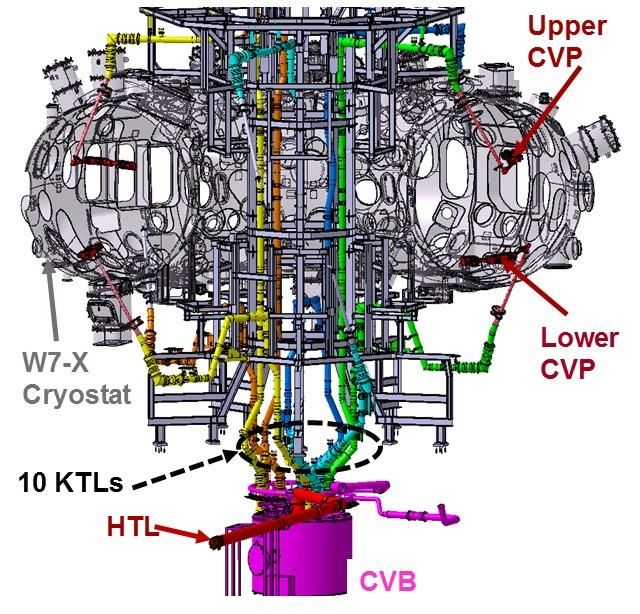
TPS12405.R1 2
III. UPGRADES TO SUPPLY NEW COMPONENTS length of 4.6 meters and a maximum weight of 350 kg each.
A. Motivation
Each of the ten new cryo vacuum pumps (CVP) needs to be
supplied with liquid helium and liquid nitrogen. Therefore a C. New valve box for the CVP
new CVP main transfer line from the existing cryo plant to a The cryo vacuum pump valve box (CVB) is located in the
new cryo valve box (CVB) and ten new transfer lines from the second basement underneath the W7-X, close to the existing
CVB to the cryo pumps have to be designed, produced and valve box for the magnet system. The main purpose of the
installed. In addition, a new liquid nitrogen storage tank is CVB is to distribute the helium as well as the nitrogen flow
necessary. The nitrogen consumption due to the operation of coming via the CVP main transfer line to the ten cryo pumps
the cryo pumps would otherwise require the delivery of liquid via the individual CVP transfer lines. In addition, the cold
nitrogen every other day. Fig. 1 shows the main components valves, temperature sensors, mass flow sensors and pressure
of the cryo supply for the cryo vacuum pumps in relation to sensors are part of the box. To handle different heat loads on
the W7-X cryostat and the inner support tower. the cryo pumps each individual feed process line can be
controlled by a separate valve. The return flows are collected
in two headers, one for helium and one for nitrogen. The
helium return flow will go back to the refrigerator. The
nitrogen return flow will be partly used for pre-cooling of
helium inside the refrigerator and then released into the air
outside the building.
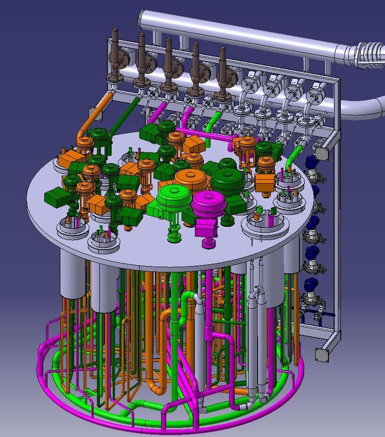
The CVB will have an outer diameter of 2.5 meters and a
height of about 2 meters (without auxiliary components). The
expected mass is in the order of 5 tons. Like most of the other
components of the cryo pump supply system the box is made
of stainless steel. The CVB contains also the safety valves for
all process pipes of the transfer lines, the CVP main transfer
line as well as of the ten individual CVP lines. Fig. 2 shows
the CAD model of the CVB.
Fig. 1. Main components of the cryo supply of the cryo vacuum pumps in
W7-X (CVP: cryo vacuum pump; CVB: cryo pump valve box; KTL:
individual transfer line from the CVB to the cryo pumps; HTL: main transfer
line from the sub-cooler box to the CVB).
B. New CVP main transfer line
The CVP main transfer line is a multi channel transfer line
containing two process pipes for helium and two process pipes
for nitrogen. The outer diameter of the vacuum jacket is 273
mm, whereas the process pipes have a diameter of 48 mm
each. All pipes are made of stainless steel 1.4571, as requested
by the general design requirements of W7-X for helium pipes
near the cryostat. The proper distance and a good thermal
separation between the process pipes will be secured with
supports made of glass fiber reinforced plastic (GRP). For
better thermal insulation, the helium pipes are wrapped with
superinsulation. The nitrogen return line is connected by
brazing to a thermal shield made of copper. The vacuum of the
transfer line is separated from the vacuum of the sub cooler
box of the refrigerator and from the vacuum of the new valve Fig. 2. CAD model of the CVB (shown without housing) with the valve rack
box. The total length of the transfer line will be 55 meters. To in the back and the collector lines for the nitrogen and helium return flows.
allow the assembly under the very tight space conditions the
transfer line consists of 13 individual segments with maximum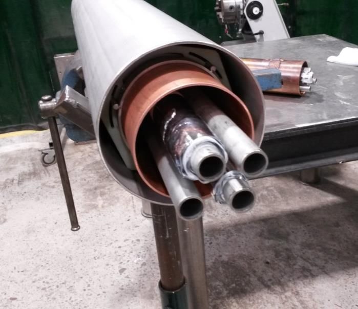
TPS12405.R1                                                                                                                                     3

   As usual, the CVB design gives the possibility to establish a     original design. All these new conditions had a considerable
short circuit between the feed and return line of the main CVP       influence to the necessary design resources and to the time
transfer line, and closing the valves to the cryo pumps at the       needed to find an acceptable technical solution. In general, it
same time. This will lead to a decoupling of the W7-X from           is one of the drawbacks of the strategy for a stepwise
the supply system without stopping the mass flows from the           completion of a complex system. From the technical point of
refrigerator. Especially during the commissioning and for tests      view, the design had to be made from the outside to the inner
and adjustments this function will be useful. The CVB                side instead of the usual way from the inner side (process
contains also electrical heaters in the process pipes (1 kW in       requirements) to the outer side. That means at first the
the helium line and 8 kW in the nitrogen line) to simulate the       maximum available outer diameter was the outer limit of the
heat load on the cryo pumps and their individual transfer lines.     outer vacuum pipe of a transfer line. The process pipes with
The valve box control, the processing of the sensor signals and      the supports and the thermal shield and the thermal insulation
the data collection will be performed by a local PLC                 had than to be designed accordingly. That led to relatively
(Programmable Logic Controller), which will be installed in a        small process pipe diameters, higher pressure drop and higher
rack close to the CVB.                                               thermal losses. The final lengths vary between 12 meters and
   Another rack associated to the CVB will host the vacuum           16 meters. Nevertheless, it could be managed to keep some
pumping unit for the CVB and for all transfer lines.                 standardization in the design. All transfer lines have an outer
   The CVB is handled as a separate project that means the           diameter of 159 mm on its straight parts, at locations with
procurement is being done independently from the                     direction changes the diameter is 219 mm. The process pipes
procurement of the transfer lines. It reduces the workload to a      have an outer diameter of 21.3 mm and a wall thickness of 2
single supplier and allows a parallel execution of the orders        mm. The helium lines are wrapped with 10 layers of
for transfer lines and CVB. On the other hand, the effort for        superinsulation each. The return line of the nitrogen pipe is
coordination and a detailed interface description is higher on       connected to the thermal shield tube, made of 2 mm thick
the side of the contractor.                                          copper and 105 mm diameter. In addition, the thermal shield is
   The CVB is being designed and built in industry by the            wrapped with superinsulation. Fig. 3 shows a picture of a
company Cryoworld in Wieringerwerf, Netherlands. The                 production sample.
contract was placed in June 2018. In July 2019 the status is as
follows: the final design of the CVB was approved in May
2019, the design of the external piping is running, the
fabrication of the box is expected to start in August 2019, and
will be ready for shipment in autumn 2019. The installation in
W7-X will be completed in first half of 2020, when all transfer
lines will be in place.

D. New transfer lines from the valve box to the cryo pumps
   The ten transfer lines to the cryo pumps are running from
the CVB to a dedicated port at the outside of the cryostat. The
ports serve as the interface to the in-vessel-pipes which serve
finally the cryo pumps. The cryo pumps in W7-X are placed
symmetrically around the circumference of the plasma vessel
and symmetrically to the horizontal plane of the plasma vessel
as well. That means five cryo pumps are located in the upper
part of the vessel, and five cryo pumps are located in the lower
part of the vessel. Therefore, the transfer lines are divided into
transfer lines for the upper cryo pumps and transfer lines for       Fig. 3. Production sample of a transfer line running from the CVB to the cryo
the lower cryo pumps. The basic concept was that all the five        pump. Helium lines (top left and lower right tubes) are wrapped with
upper and all the five lower transfer lines should have the          superinsulation.
same routing. Unfortunately the installations outside of the
W7-X basic machine like cable trays, water pipes, support
structures and of course diagnostics are not symmetrically             Each transfer line has its own vacuum. There are vacuum
anymore. The originally reserved space for the transfer lines        barriers to the CVB and to the cryo pump ports of the W7-X
are meanwhile used by other components. The main                     machine. The vacuum shell is equipped with safety valves to
consequence was that the routing of each transfer line had to        avoid overpressure in failure conditions like the break of a
be adapted to the individual space restrictions of a specific        process pipe.
transfer line. The transfer lines now have individual routings         The final design of the transfer lines, the main transfer line
and several direction changes were necessary compared to the         (chapter III B) as well the ten small transfer lines to the cryo
TPS12405.R1                                                                                                                         4

pumps was made together with industry in a one year contract.        pressure is 19 bars, but the operating pressure is adjustable
The fabrication of the transfer lines was awarded in April           between 2 and 10 bars. As the new tank will be used only for
2017 to the same company, Cryotherm from Kirchen,                    an extension of the delivery duration and not to an increase of
Germany, and is presently running. By July 2019 nine of the          the delivered mass flow rate, the existing transfer line with a
ten short transfer lines have been fabricated. Eight of them are     nominal diameter of 40 mm from the tank to the cold box of
already installed in W7-X. The design of the main transfer line      the helium refrigerator will not be doubled.
is finished, the production will start in August 2019 and all           By July 2019, the basic design requirements have been
segments are planned to be delivered to the W7-X site by end         defined. The drafting of the technical specification is going to
of 2019. The installation sequence of all the described              start in autumn this year.
components is as follows: Due to the space constraints the
transfer lines to the cryo pumps will be installed first, than the
main transfer line will be installed. The installation of the
transfer lines requires the welding of the segments on-site.              IV. UPGRADES BASED ON OPERATION EXPERIENCES
First, the welding of the four process pipes, then the
                                                                     A. Motivation
application of the superinsulation and finally closing of the
vacuum jacket by welding. Afterwards the CVB will be                    During commissioning and operation of the W7-X several
brought at its final place. The last step will be the connection     fast discharges of the superconducting magnet system were
of all transfer lines to the CVB. The auxiliary components will      conducted, planned as well as unplanned. Test of safety
be installed afterwards, the vacuum pump for the 12 vacuum           systems as well as general failures like loss of the grid voltage
zones, the rack with the sensor electronics and the local            normally lead to a trip of the refrigerator’s connection to the
control system. The completion of all the tasks is planned for       W7-X by closing the valves. One experience was that in all
mid of 2020.                                                         cases were the cryo plant was disconnected from the W7-X
                                                                     and the screw compressors tripped the restart procedure
                                                                     created problems with the handling of the cold helium gas. To
                                                                     improve the gas handling, an additional heat exchanger is
E. New liquid nitrogen storage tank                                  being designed. A second measure to improve the handling of
   Up to now the cryo plant was operated without any usage of        the helium gas is the procurement of an additional helium gas
liquid nitrogen for supporting the refrigeration process. When       storage tank.
the cryo pumps have been integrated in the system a different
operation regime will be used.
   The helium refrigerator has to take an additional load of
                                                                     B. Additional heat exchanger for cold helium gas
450 W at 4 K when the CVP are in operation. Therefore, the
cooling power of the cryo plant will be increased by using              The cryo plant will be automatically disconnected from
377 l/h (steady-state) of LN2 for pre-cooling. The heat load on      W7-X cryostat in case of a trip of the cryo plant caused by
the shield of the CVP requires 93 l/h LN2 in standby                 instable operation regimes, signal failures or utility failures.
condition. Stand-by condition means the whole day except the         The quench of the superconducting magnets or a fast
duration of the plasma shots. During plasma operation with           discharge can also lead to a trip of the cryo plant. A full
ECRH heating the expected heat load of up to 12 kW to the            reconnection of the cryo plant with the W7-X cryostat after
CVP requires up to 320 l/h of LN2. Assuming a daily plasma           the reason for the trip has been clarified, requires that the
operation of 3 hours, the total liquid nitrogen consumption          process pipes together with the helium volumes must be
will be 11960 liters per day.                                        depressurized inside the W7-X cryostat first.
                                                                        The helium amount inside the cryostat is about 470 kg.
   The existing liquid nitrogen tank has a nominal volume of         Depressurizing requires that a big fraction of that cold helium
30,000 liters, but due to safety restrictions and the need of        (liquid/gas) have to be warmed up to room temperature and
keeping always a minimum level in the tank the usable                returned to the gas storage within a few hours.
volume is about 20,000 liters only. Taking into account the             Kilograms of gas or liquid helium will flow back from the
expected consumption as stated above, it is clearly visible that     W7-X cryostat through the heat exchangers of the cold box.
a 3-days-per-week operation regime as it is planned for the          The mass flow cannot warm up inside the counter flow heat
next campaigns of W7-X requires at least one refilling during        exchangers because there is not any relevant warm counter
the operation week. In case of a skipped or even delayed             flow to balance the heat exchange. So cold gas leaves the cold
delivery of LN2, the operation week would have to be stopped         box and enters the suction side of the warm compressor.
or interrupted. To overcome this potential risk, it was decided      Finally, the compressor unit pushes the outlet gas to the warm
to install a second LN2 storage tank.                                storage tanks.
   The new tank will be a copy of the existing tank. It is a            The cold gas cools down the carbon steel end cap of the
double wall tank, the inner vessel is the product vessel and the     cold box and the temperature might drop below the lower
outer vessel serves as the cryostat. The new tank will have a        acceptable limit for that carbon steel (about 223K). This might
usable volume of 30 cubic meters. The maximum allowed                lead to embrittlement. Humidity will freeze on the cold
TPS12405.R1 5
connection pipes. The lubrication oil inside the compressors of the fifths tank slightly deviates from the design of the first
might cool down below the allowed limits and might even four tanks, but the main parameters are similar. As the first
freeze. Therefore, it is planned to install a parallel flow path four tanks, the new tank has a volume of 250 cubic meters, is
that comes into action when the cold box is disconnected. This made of carbon steel (material number 1.0566), and has a
flow path allows heating of the return flow to ambient length of 22 meters and an outer diameter of 4 meters. The
temperature with the help of a conventional fin tube heat maximum operation pressure is 18 bar, safety valves are
exchanger located outside the building and taking the required installed to avoid dangerous overpressure.
heat from the environment. The enlarged storage volume offers the change to use the
new tank as a dedicated quench gas tank. That makes it
The new heat exchanger will consist of two units of a power possible to customize the interface to the quench gas line
of 50 kW each. The layout will be similar to the one existing accordingly. In case of a quench the helium gas coming from
heat exchanger using external fin tubes in vertical orientation the magnets can contain a certain amount of liquid helium as
made of aluminum. The design inlet temperature is 40 K at a well. To avoid that liquid helium drops onto the bottom of the
mass flow of 70 g/s. The whole system will be installed carbon steel tank with the risk of overstressing the material
outside of the cryo building. (the minimum allowed temperature is -60°C for the used
By July 2019, the preliminary design has been finished and carbon steel), the helium inlet is equipped with an internal
the technical specification was drafted. diffusor. The diffusor is an 18 meters long pipe of 170 mm
diameter in the inner volume of the tank and has 720 small
holes (every 200 mm 8 holes around the circumference) with a
diameter of 7 mm. The helium is sprayed through these small
C. Additional warm helium gas tank
holes into the tank and mixes with the warm helium in the
The present concept of the gas storage system foresees a tank. This warms it up and distributes it more uniformly in the
storage volume of 4x250 cubic meters for helium gas at max. volume.
19 bar. This concept secures that in case of warming up to The tank was designed, build tested delivered in industry, by
room temperature the total helium inventory of the W7-X as the company A. Silva-Matos from Aveiro, Portugal. The
well as of the helium refrigerator plant is possible to store in contract was placed in October 2017, the design was finished
gas tanks. The remaining pressure in the systems is than in the in December 2017, the fabrication ran in 2018 and the tank
uncritical range of 2-3 bar. But in case a significant amount of arrived at its final place next to the existing tanks in December
helium is lost during operation caused by blow off of safety 2018. The pipe, which connects the new tank with the other
valves or even a breakage of rupture discs no spare helium tanks and with the quench gas line from the W7-X is under
would be available to continue with the operation. Further design. The integration into the existing system will be
helium leakages and purging procedures after maintenance finished in 2021.
activities also leads to loss of helium. At the time of the design
in the mid-90s of the last century, this was no issue, but
meanwhile the price for helium has increased drastically and
there is a shortage of helium on the market. Therefore, it was V. SUMMARY
decided to buy one additional helium gas storage tank with a The cryogenic systems of Wendelstein 7-X were
volume of 250 cubic meters. This will enlarge the total storage successfully operated during the first three experimental
volume by 25%. The total storage volume of the five tanks is campaigns in 2015, 2016 and 2018. During the completion
now large enough to store the total amount of helium gas of phase of W7-X a major upgrade is running. There are two
the W7-X cryo systems. This avoids the loss of helium during main motivations for the upgrade. The first set of measures are
opening of the cryo plant and/or the W7-X cryo line necessary to supply the new components in the plasma vessel,
distribution system. the ten cryo vacuum pumps, with helium and nitrogen. The
Also in case of a quench the storage volume will be large second set of measures is based on operation experiences and
enough to have always one tank available for taking over the will also support the robustness of the cryo systems during the
gas after a quench. In general the sequence in case of a quench upcoming experimental campaigns. The upgrade activities, are
is as follows: Before the experiment starts, it is ensured that running internally and in industry and progressing well.
the dedicated quench gas tank has a pressure of 1.3 to 1.5 bar.
In case of a quench the safety valves open at a pressure of 17
bar and helium can flow into the quench tank. Later the warm ACKNOWLEDGMENT
screw compressors are used to empty the quench tank again The authors thank all the involved colleagues in IPP as well
and pump the gas into the other storage tanks sitting at higher as the various industrial partners for the valuable
pressure. contributions.
The design of the new tank was tried to make as similar as
possible with respect to the existing tanks. Unfortunately, the
company, which designed and delivered the first four tanks in
the year 2000, does not exist anymore. Therefore, the designTPS12405.R1 6
REFERENCES Andreas Braatz, photograph and biography not available at
the time of publication.
[1] H.-S. Bosch et al., “Final integration, commissioning and
start of the Wendelstein 7-X stellarator operation,” Nucl. Marko Ihrke, photograph and biography not available at the
Fusion, vol. 57, no. 11, p. 116015, 2017. time of publication.
[2] T.S. Pedersen et al., “First results from divertor operation in
Wendelstein 7-X,” Plasma Physics Contr. Fusion, vol. 61,
p.014035, 2019.
[3] R. Wolf et al., “Major results from the first plasma Hans-Stephan Bosch has studied physics
campaigns of the Wendelstein 7-X stellarator,” Nucl. in Münster and Munich. He received the
Fusion, vol. 57, no. 11, p. 102020, 2017.
[4] M. Hirsch at el., “Major results from the stellarator Dr. rer. nat. degree from the Technical
Wendelstein 7-X,” Plasma Phys. Control. Fusion 50, University, Munich, in 1986, and the
053001 (2018). doi:/10.1088/0741-3335/50/5/053001 Habilitation degree from Humboldt
[5] G. Ehrke et al., “Design and manufacturing of the University, Berlin, Germany, in 2000. In
Wendelstein 7-X cryo-vacuum pump,” Fusion Eng. and
Design, Volume 146, Part B, September 2019, pp. 2757- August 2016 he was appointed as a
2760. professor at TU Berlin.
[6] C. P. Dhard, M. Nagel, S. Raatz, U. Nuesslein, and M. After his post-doc- time at TFTR in
Ressel, “Final acceptance tests of helium refrigerator for Princeton, he worked on ASDEX and ASDEX Upgrade at
Wendelstein 7-X,” Physics Procedia, vol. 67, pp. 83-88,
2015. IPP, Garching. In 2000 he changed the field, becoming head
of the Director’s Office. In 2004 he joined the project
Wendelstein 7-X as head of Project Coordination. Since 2013
he is the “Director Operations” for Wendelstein 7-X and
deputy head of W7-X of the Max-Planck-Institute for Plasma
Thomas Rummel has studied Electrical Physics.
Engineering and received the Dipl.-Ing.
and the Dr.-Ing. degrees from the
University of Magdeburg, Germany, in
1989 and 1996, respectively. He joined
the Max-Planck-Institute for Plasma
Physics (IPP) Garching in 1998 and has
been working for Wendelstein 7-X in the
IPP Greifswald in the fields of
superconducting magnets, magnet protection and magnet
power supplies since then. In 2001, he became the head of the
magnet and power supply department. Since 2015 he is the
head of the magnet and cryogenics division of
Wendelstein 7-X.
Michael Nagel received the Dipl.-Ing. and
Dr.-Ing degrees in Chemical Engineering
from the Technical University of
Karlsruhe, Germany in 1990, and from the
University of Karlsruhe in 1995,
respectively.
He joined the Max-Planck-Institute for
Plasma Physics, Greifswald, Germany in
1999. He has been involved in cryogenics
for Wendelstein 7-X Project. He is leader of the cryogenic
team. His working field covers thermodynamics, fluid
dynamics and their applications in cryogenics.
Michael Pietsch, photograph and biography not available at
the time of publication.
Sylvio Raatz, photograph and biography not available at the
time of publication.
C. P. Dhard, photograph and biography not available at the
time of publication.You can also read