Delamination properties and in situ damage monitoring of z-pinned carbon fiber/epoxy composites
←
→
Page content transcription
If your browser does not render page correctly, please read the page content below
Science and Engineering of Composite Materials 2021; 28: 415–425
Research Article
Zhe Che, Han Wang*, Shaokai Wang*, Yizhuo Gu and Min Li*
Delamination properties and in situ damage
monitoring of z-pinned carbon fiber/epoxy
composites
https://doi.org/10.1515/secm-2021-0041 of damage detection. The ΔR/R0 of CCF800 z-pinned com-
received April 11, 2021; accepted July 06, 2021 posite is nearly three times that of the control sample at the
Abstract: Carbon-fiber-reinforced composites with layer moment the crack length reaches 110 mm. Crack length–
stacking structures are sensitive to delamination crack. To displacement curves were obtained according to the rela-
improve the interlaminar properties and further explore tionship between ΔR and Δa, which clearly displayed the
the capability of in situ damage monitoring of the lami- steady or stick-slip crack growth of the laminates with or
nate, CCF300 and CCF800 carbon fiber pins were selected without z-pins, respectively. Visualization of the crack
to fabricate the z-pinned composites. Compared with the growth process can provide a novel method for the dela-
control sample, the GIC values of CCF300 and CCF800 mination failure analysis of the composite.
z-pinned composites are increased by 398 and 378%, Keywords: z-pin composite, interlaminar fracture tough-
respectively. This indicates that the delamination resis- ness, in situ damage monitoring
tance improvement of the laminates is dominated by the
z-pin debonding and pull-outs. The electrical resistance of
the laminates was utilized to in situ monitor the crack
propagation within the composite laminate. The results 1 Introduction
show that the presence of the z-pins enhances the sensitivity
Carbon-fiber-reinforced composites exhibit high specific
strength and modulus, designability of ply direction and
shape, and are suitable for integral molding [1,2]. How-
* Corresponding author: Han Wang, State Key Laboratory of Fluid
ever, composite laminates are sensitive to delamination
Power and Mechatronic System, School of Mechanical Engineering,
crack [3] due to the layer-by-layer stacking structure.
Zhejiang University, Hangzhou 310027, China,
e-mail: wang_h2018@zju.edu.cn Various techniques such as stitching [4], 3D braiding
* Corresponding author: Shaokai Wang, Key Laboratory of [5,6], and z-pining methods improved the interlaminar
Aerospace Advanced Materials and Performance (Ministry of properties and have aroused extensive interest. Although
Education), School of Materials Science and Engineering, Beihang the z-pins result in an unavoidable reduction in the in-
University, No. 37 Xueyuan Road, Haidian District, Beijing 100191,
plane elastic modulus [7], tension [8], compression [9],
China; Ningbo Institute of Technology, Beihang University,
Ningbo 315800, China, e-mail: wsk@buaa.edu.cn
bending [10], and fatigue performance [11], the reduction
* Corresponding author: Min Li, Key Laboratory of Aerospace in the in-plane mechanical properties caused by z-pins is
Advanced Materials and Performance (Ministry of Education), usually modest (5–30%) in contrast to the very large
School of Materials Science and Engineering, Beihang University, improvements in interlaminar fracture toughness (above
No. 37 Xueyuan Road, Haidian District, Beijing 100191, China; 400%) [12]. Therefore, z-pinning has attracted extensive
Ningbo Institute of Technology, Beihang University, Ningbo 315800,
attention [13,14] as an interlaminar reinforcement method.
China, e-mail: leemy@buaa.edu.cn
Zhe Che: Key Laboratory of Aerospace Advanced Materials and The bridging effect of z-pin plays an important role in
Performance (Ministry of Education), School of Materials Science the interlaminar fracture toughness improvement [15]. In
and Engineering, Beihang University, No. 37 Xueyuan Road, z-pinned composite laminate, crack growth is prevented
Haidian District, Beijing 100191, China through the interaction between z-pins and the sur-
Yizhuo Gu: Key Laboratory of Aerospace Advanced Materials and
rounding laminates. The pullout of z-pins from the lami-
Performance (Ministry of Education), School of Materials Science
and Engineering, Beihang University, No. 37 Xueyuan Road, Haidian
nate consumes a large amount of energy [16], resulting in
District, Beijing 100191, China; Ningbo Institute of Technology, the improvement of fracture toughness. The influences of
Beihang University, Ningbo 315800, China the z-pin volume content [17–20], z-pin diameter [21,22]
Open Access. © 2021 Zhe Che et al., published by De Gruyter. This work is licensed under the Creative Commons Attribution 4.0 International
License.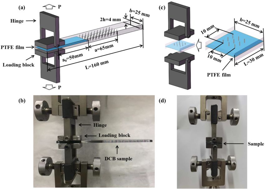
416 Zhe Che et al.
and z-pin angle [23,24] on the improvement to the GIC 100 g/m2, and the thickness of cured single ply was about
of the composites have been extensively researched. For 0.1 mm. CCF300 and CCF800 carbon fibers were used to
the z-pin properties, Pingkarawat and Mouritz [25] made prepare the pins that had a diameter of 0.5 mm. The length
z-pins from copper, steel, and carbon fiber to enhance the of the z-pins was 4 mm.
interlaminar fracture toughness of laminated plate. Their
work proves that the carbon fiber is the most effective
reinforcement material. However, the effect of the carbon
fiber properties on the GIC of the composites needs further 2.2 Fabrication of z-pinned carbon fiber/
exploration. epoxy composites
At present, academics and industry are not only satis-
fied with improving delamination resistance of carbon- The ply scheme of the composite laminates for DCB tests
fiber-reinforced composites but also interested in detecting was set as [0]40, and a PTFE film with a thickness of 13 μm
the crack initiation within the laminates during the service was placed in the midplane of the laminates during lay-
period. Once the crack is initiated, the delamination will up to form an initiation site for the delamination. CCF300
expand rapidly until the structure fails [26,27]. Acoustic or CCF800 z-pins were implanted in the crack propaga-
emission and c-scan have been used in nondestructive tion region. The prepregs were heated to soften on a hot
testing for polymer composites [28,29]. However, neither table at 30 ± 1°C. The carbon fiber pins were embedded
the c-scan nor acoustic emission method can quantita- vertically into the prepregs. The rest of the pins were cut
tively analyze the structure and processing quality of the off from the top surface of the prepregs. The crack pro-
z-pinned composites. Due to the conductivity of carbon pagation region of the specimen covering an area of
fiber pins [30], three-dimensional conductive paths formed 25 mm × 65 mm was inserted with 48 z-pins arranged
by z-pins in the laminates provide the possibility for damage in a square grid pattern consisting of four columns
detection [31,32]. For z-pinned composites, the existence of (0° direction) and twelve rows (90° direction). The
carbon fiber z-pins enhances the sensitivity of in situ damage volume fraction of z-pins was 0.6 vol% with a pin-to-
monitoring within the laminates [33,34]. pin spacing of 5 mm. The z-pinned composite samples
In this article, we aimed to analyze the effect of dif- were cured in an autoclave at a pressure of 0.5 MPa. The
ferent pin properties on the interlaminar fracture tough- temperature scheme was 80°C/30 min + 120°C/90 min, and
ness of z-pinned composites. The failure behaviors of the heating rate was controlled at 1°C/min.
z-pin debonding and pulling out were observed via the
z-pin traction load test and the failure morphologies.
Meanwhile, the electrical resistance of laminates was
measured in real time to reflect steady or stick-slip crack 2.3 Characterization and testing
growth of the control sample and the z-pinned compo-
sites, respectively. The sensitivity of different pins to 2.3.1 Double cantilever beam test
damage monitoring was evaluated. The crack length–
displacement curve was created by the established equa- Mode I interlaminar fracture toughnesses (GIC) of control
tion and accurately corresponded to the load–displacement and z-pinned composites were measured using the DCB
curve of the double cantilever test. test in accordance with ASTM D5528. The specimen size
was 160 mm × 25 mm. As shown in Figure 1a and b, alu-
minum loading blocks were bonded to top and bottom
surfaces at the sample edge. The size of the loading
blocks was 30 mm × 25 mm × 8 mm. The loading block
2 Experimental connects with a hinge via a bolt. Thus, the load was
maintained perpendicular to the sample during the test.
2.1 Materials The initial crack length, set to 50 mm, was measured from
the midpoint of the loading block to the end of the
Carbon fiber unidirectional prepreg UIN10000/9A16 was inserted PTFE film. Before the DCB test, both the edges
purchased from China Weihai Guangwei Composite of the specimen were coated just ahead of the insert with
Material Co., Ltd. This unidirectional prepreg consisted a thin layer of white background. The 60 mm from the
of CCF800 carbon fiber and 9A16 epoxy resin, and its resin insert film on either edge was marked with thin vertical
content was 33–34%. The area density of prepreg was lines every 1 mm. During the DCB test, a traveling optical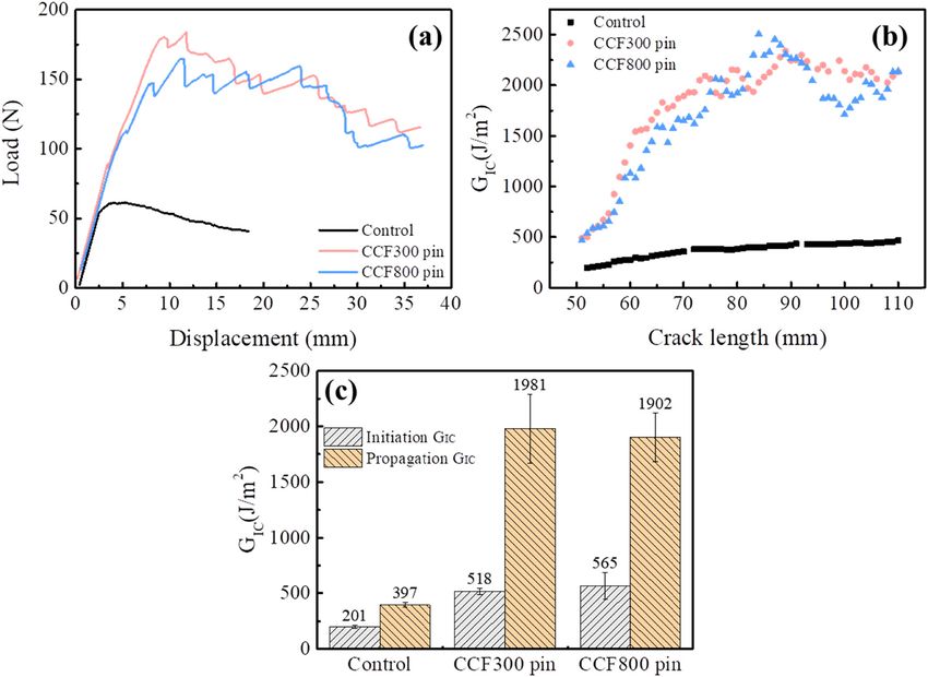
Delamination properties and in situ damage monitoring of composites 417
Figure 1: Schematic illustration of the experimental specimens for the (a) DCB test and (c) z-pin traction load test; the photograph of the
(b) DCB test and (d) the z-pin traction load test.
microscope was used to record the crack growth at every 3 ⎛ δ ⎞2 3 ⎛ δt ⎞
F=1− − , (2)
1 mm, up to a mark of 60 mm. The delamination length of 10 ⎝ α ⎠ 2 ⎝ α2 ⎠
the sample was the sum of the initial crack length and the
where t is the sum of the one-half thickness of the loading
increment of the growth determined from the tick marks.
block and one-fourth thickness of the DCB sample.
The DCB test was carried out at a crosshead speed of
1 mm/min by using Instron 3344 universal testing machine
with a 5 kN loading cell. Five samples of each type of 2.3.2 Z-pin traction load test
composite were tested under identical conditions. The
GIC values were calculated based on the corrected modified To analyze the failure behavior of z-pin during the crack
beam theory (MBT) formula as follows: opening, the tensile test along the thickness direction
of the composite laminate was carried out to measure
3PCδ
G IC = × F, (1) the z-pin traction load. The specimen consisted of two
2b(a + ∣Δ∣)
parts of carbon fiber/epoxy laminate that were separated
where δ is the load point displacement, PC is the applied by the PTFE film in the middle plane. The specimen had a
load, a is the crack length, b is the specimen width, and dimension of 30 mm × 25 mm, which contained the z-pin
Δ is the effective delamination extension to correct for array in an implantation area of 1 cm2, as shown in
the rotation of DCB arms at the delamination front, and Figure 1c and d. The volume fraction of z-pin was con-
F is the large displacement effects correction parameter trolled at 0.4, 1.2, and 2.4 vol%, which corresponded to
given by the z-pin number of 2, 6, and 12, respectively. The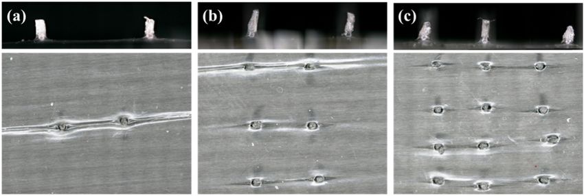
418 Zhe Che et al.
specimens were tested at a tensile speed of 1 mm/min by were taken at different magnifications in order to investigate
using Instron 3344 machine with a 5 kN loading cell. Five the factors of interlaminar fracture toughness improvement.
samples of each type of composite were tested under
identical conditions.
3 Results and discussion
2.3.3 Z-pin tensile test
3.1 Mode I interlaminar fracture toughness
To further analyze the influence of carbon fiber pin prop-
erties on the GIC of the laminates, the tensile property of of z-pinned composites
z-pin was measured by using Instron 3382 universal
testing machine at a tensile speed of 1 mm/min in accor- The representative load–displacement curves of control
dance with ASTM D4018. Both the ends of impregnated and z-pinned composites during DCB tests are shown in
fiber tow were bonded on a stiffener tab with a gauge Figure 3a. These load–displacement curves can be divided
length of 250 mm. Five samples of each type of composite into linear and nonlinear regions. The linear region indi-
were tested under identical conditions. cates no fiber bridging effect before crack initiation due to
the presence of the PTFE film. The initiation value for GIC
should be recorded corresponding to the load and displa-
2.3.4 Electrical resistance measurement cement when the crack contacts the first vertical mark after
the precrack tip. The control and z-pinned samples show
DMM6500 digital multimeter was used to measure the different load–displacement curve profiles in the non-
electrical resistance of the composite laminate. Copper linear regions. For the control sample, the load values
foil electrodes were bonded to the sample edges by using drop smoothly. The crack propagates at a constant velocity
silver glue, which ensured a good electrical connection in the midplane of the laminate, while the load–displace-
between the specimen and the electrodes. The in situ ment curves of the two z-pinned composites show a jagged
measurement setup of the electrical resistance during profile. This phenomenon manifests that z-pins play an
the DCB test is shown in Figure 2. important role in the way of crack growth. The way of
crack growth is changed from the stable propagation in
the control sample to “stick–slip” behavior in z-pinned
2.3.5 Morphology observation samples. When the crack contacts a row of z-pins, the
load values increase steadily. As the opening displacement
A three-dimensional optical microscope system VHX- increases, z-pins bridge the delamination at the crack tip,
6000 was used to examine z-pin morphologies and and then the z-pins are debonded and pulled out from the
the fracture surface of the measured specimen. Images surrounding laminates. Once they are pulled out comple-
tely, the accumulated energy is partially released and the
crack propagates suddenly. The load values display a
sharp reduction. The load values increase again when
the crack tip contacts the next row of the z-pins. Therefore,
the load values show the periodical drop and increase
during the crack propagation.
Figure 3b shows the delamination resistance curve of
the control sample and the z-pinned composites. The GIC
of the control sample is increased gradually and tends to
be stable when the crack length reaches 70 mm. The
interlaminar fracture toughness of the control sample is
dominated by fiber bridging. As the crack propagates, the
bridging fibers are broken or pulled out from the resin
due to the separation of the double cantilever beam.
When the number of bridging fibers per unit crack area
Figure 2: In situ monitoring of electrical resistance during the is equal, the steady fracture toughness will be obtained.
DCB test. The fracture toughness values of the z-pinned composites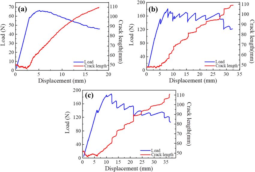
Delamination properties and in situ damage monitoring of composites 419
Figure 3: (a) Typical mode I load–displacement curves of DCB tests, (b) delamination resistance curve, and (c) mode I initiation and
propagation fracture toughness values of control and z-pinned composites.
are much higher than that of the control sample. The pin- properties of z-pins are listed in Table 1. The tensile modulus
ning effect of the z-pins suppresses the extension of the of the CCF800 carbon fiber is higher than that of the CCF300
crack tip. The failure behaviors of the z-pins debonding carbon fiber. The CCF300 pins are prone to bending when
and pulling out absorb energy to enhance the delamina- the delamination surfaces separate from each other. The
tion resistance of the laminates. bending deformation could absorb partial energy, resulting
Figure 3c shows the initiation and propagation GIC in the slightly higher propagation GIC value of the CCF300
values of the control and z-pinned composites. The initia- z-pinned composite than that of the CCF800 z-pinned
tion GIC value of the control sample is 201.2 J/m2, while composite.
the initiation GIC values of CCF300 and CCF800 z-pinned
composites are 518.5 and 564.6 J/m2, respectively. The
propagation GIC value of the control sample is 397.6 J/m2, 3.2 Fracture surface morphologies and
and the propagation GIC values of CCF300 and CCF800 failure mechanism
z-pinned composites are 1980.8 and 1902.1 J/m2, respec-
tively. These results demonstrate that z-pins provide the Figure 4a shows the opening crack morphology of the
crack bridging traction load, resulting in the significant z-pinned specimen during the DCB test. As the crack length
enhancement of interlaminar fracture toughness. The tensile reaches 110 mm, the crack opening displacement (COD) of
the control sample is 18 mm, while the COD of the z-pinned
composite is increased significantly to 35 mm. In the
Table 1: Tensile properties of the different z-pin fibers
z-pinned composites, z-pins provide the traction load during
Strength (MPa) Modulus (GPa) Strain (%) the delamination process, which effectively suppresses the
crack tip extension. Therefore, the z-pinned composites
CCF300 4419 ± 165 232 ± 4 1.98 ± 0.12
need larger crack opening displacement to induce crack to
CCF800 5607 ± 133 292 ± 7 1.93 ± 0.07
propagate to the same length as the control sample.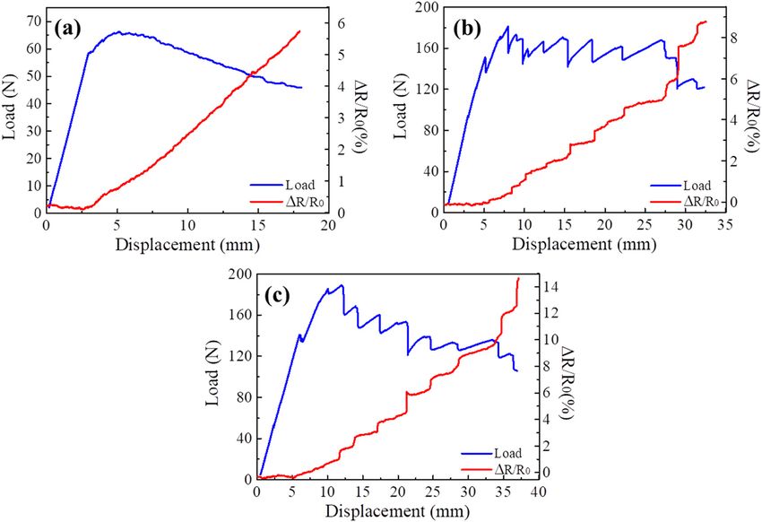
420 Zhe Che et al.
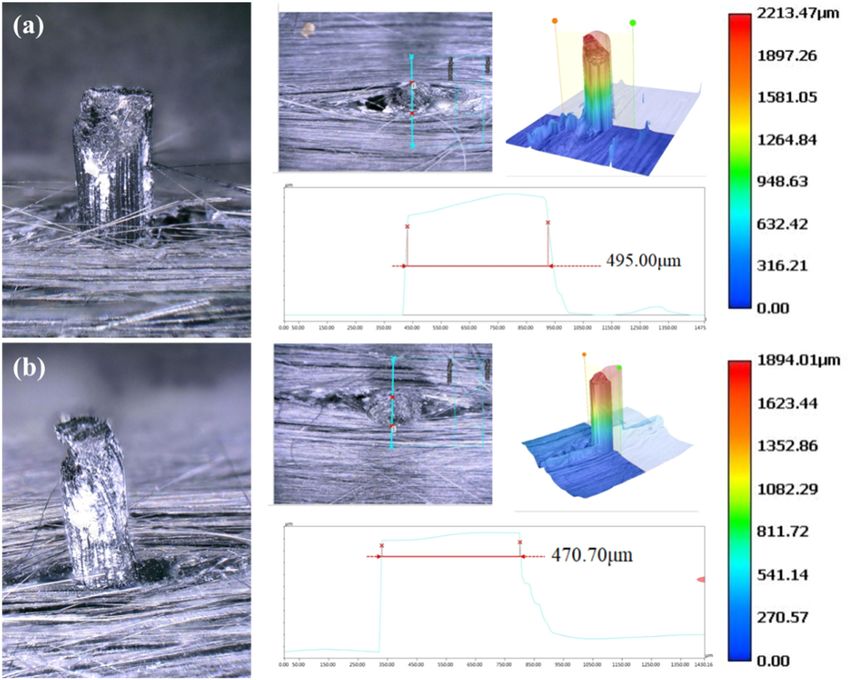
Figure 5a and b show the surface morphologies of
CCF300 and CCF800 z-pins in the fractured samples.
The polymer resin partially wraps z-pins as seen in the
white area. When z-pin is inserted into the unidirectional
laminate, an eye-shaped resin-rich region is formed
around the z-pins. During the z-pins pulling out from
the eye-shaped region, microcracks form at the z-pin/lami-
nate interface or inside the resin. A part of white resin
attached to the z-pin is pulled out together. The wrapped
resin on the z-pin surface indicates the presence of the
interfacial force between the z-pins and the laminate.
Figure 4: (a) Photographs of crack opening during the DCB test, and To further analyze the interface adhesion strength
failure morphologies of (b) CCF300 and (c) CCF800 specimens. between the z-pin and laminate, the traction loads at
different z-pin volume fractions were measured via the
z-pin traction load test [35], as shown in Figure 6a. A
Figure 4b and c show the failure morphologies of maximum load of 2.4 vol% sample is increased to 581 N
CCF300 and CCF800 z-pinned specimens, respectively. from 109 N of 0.4 vol% sample. All these load–displace-
The cracks in these two z-pinned composites also propa- ment curves at different z-pin volume fractions can be
gate in the middle layer during the DCB test. The bridging divided into three stages: (1) z-pins initially exert elastic
carbon fibers and pulling out z-pins in the midplane traction load to resist delamination crack opening; (2)
reduce the stress concentration in the crack front. when the bridge traction load reaches the peak point,
Figure 5: Morphologies and profiles of (a) CCF300 and (b) CCF800 z-pins in the fractured samples.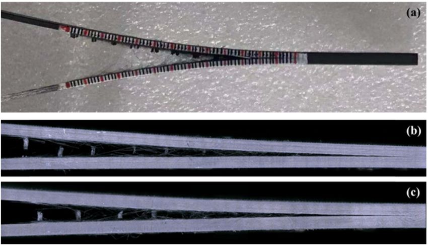
Delamination properties and in situ damage monitoring of composites 421
Figure 6: (a) Representative load–displacement curves at different z-pin volume fractions during z-pin traction load test; (b) the relationship
between the traction load with the number of z-pins.
z-pins are debonded from the surrounding laminate z-pin pull-out failure mode is observed for all these sam-
through the interface shear cracking, and consequently, ples. This indicates that the failure mode of z-pins is not
the load values are dropped partially. The shear cracking affected by the z-pin volume fraction in the z-pin traction
occurs once the traction load exceeds the shear failure load test.
stress of the z-pin/laminate interface; (3) during z-pins
pulling out from the laminate, the bridging traction load
is decreased with the increase of the crack opening dis-
placement. In the third stage, the sliding action of the z- 3.3 In situ damage sensing
pin generates the friction traction load that contributes to
the improvement of the GIC values. Finally, z-pins are In situ damage monitoring of control and z-pinned com-
pulled out of the composite laminate completely and the posites was demonstrated by measuring the real-time
traction load is decreased to zero. In order to obtain the electrical resistance during the DCB test. The electrical
interfacial shear failure load between the single z-pin and response in the DCB test is distinct from that under the
laminate, the traction load was normalized. The interfacial tensile or flexural test [36,37]. The geometric parameters
shear failure load of a single z-pin is 46.5 N, as shown in of the DCB specimen and the in situ monitoring method
Figure 6b. are shown in Figure 8. The electrodes were electrically
Figure 7 displays the failure morphologies at different connected to the top and bottom surfaces of the DCB
z-pin volume fractions during the z-pin traction load test. specimen. These two electrodes were designed to measure
Figure 7: Side and top views of failure morphologies at z-pin volume fractions of (a) 0.4 vol%, (b) 1.2 vol%, and (c) 2.4 vol% during z-pin
traction load test.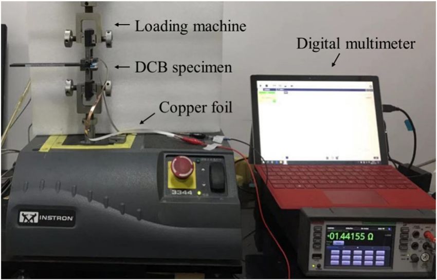
422 Zhe Che et al.
Figure 8: Schematic diagram of the measurement method for the electrical resistance at (a) initial state and (b) crack propagation state
during the DCB test.
the through-thickness electrical resistance of the DCB spe- the load values are decreased gradually for the control
cimen [38], as shown in Figure 8a. Accompanied by crack sample. The corresponding electrical resistance change,
propagation, the conduction area of the double cantilever ΔR/R0, is increased linearly, which reflects that the crack
beam is decreased. Thus, the electrical resistance increases propagates at a uniform speed in the midplane of the
gradually, as shown in Figure 8b. Therefore, the crack control sample. For CCF300 and CCF800 z-pinned compo-
growth process of laminates was reflected via the electrical sites, the ΔR/R0 is increased in a stepwise fashion. This
resistance change during the DCB test. phenomenon reflects that the periodical extension and
The load–displacement curves of control, CCF300, arrest of cracks occur in the z-pinned composites, as
and CCF800 z-pinned composites along with the corre- shown in Figure 10b and c. The different ΔR/R0 curve pro-
sponding electrical resistance curves are shown in Figure 9. files clearly manifest two ways of crack propagation during
With the increase of the crack opening displacement, the DCB test.
Figure 9: The load–displacement curve (blue) and electrical resistance change curve (red) of (a) control, (b) CCF300, and (c) CCF800
z-pinned composites.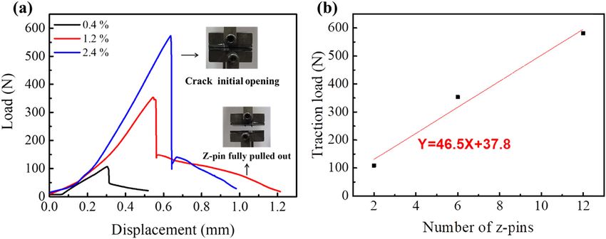
Delamination properties and in situ damage monitoring of composites 423
Figure 10: The calculated crack length with respect to the opening displacement for (a) control, (b) CCF300, and (c) CCF800 z-pinned
composites.
The ΔR/R0 curves of CCF300 and CCF800 z-pinned circuit including the electrical resistance along the fiber
composites demonstrate that the step heights in the direction of the initial crack region and the contact resis-
ΔR/R0 curve are increased step by step with the increase tance between the electrodes and the composite laminates.
of the displacement. According to Ohm’s law, R = ρL/S, To eliminate Rx, formula (5) is obtained by subtracting
where R is the resistance, ρ is the resistivity, L is the equation (3) from equation (4):
length, and S is the cross-sectional area. There is a non- ρt ρt
linear relationship between the conduction area and the R − R0 = ΔR = − . (5)
(c − Δa)w cw
electrical resistance. In order to accurately monitor the
crack growth in the DCB sample, the relationship between Equation (5) may be rewritten as equation (6):
the resistance change and the crack growth length was
ρt
calculated by Ohm’s law. The electrical resistances of the Δa = ⎛⎜1 − ⎞⎟c. (6)
⎝ ΔRcw + ρt ⎠
DCB specimen in the initial state and crack propagation
state are shown in equations (3) and (4): The relationship between ΔR and Δa is established in
ρt equation (6). The crack lengths at different displacements
R0 = + Rx , (3) are determined according to the ΔR value. Thus, an in situ
cw
monitoring method for crack length was developed based
ρt
R= + Rx , (4) on the electrical resistance change. Figure 10 shows the
(c − Δa)w
crack length and displacement curve for control, CCF300,
where t is the specimen thickness, w is the specimen and CCF800 z-pinned composites. As seen in Figure 10,
width, c is the length from the precrack front to the other the crack length is constant in the linear region of the
end side of DCB specimen, R is the through-thickness load–displacement curve. For the control sample, the
electrical resistance at a crack length of a0 + Δa, R0 is crack growth rate is decreased with the increase of
the initial electrical resistance before crack propagation, the crack opening displacement in the nonlinear region
and Rx is the electrical resistance of the other parts of the of load–displacement curve. The cracks in CCF300 and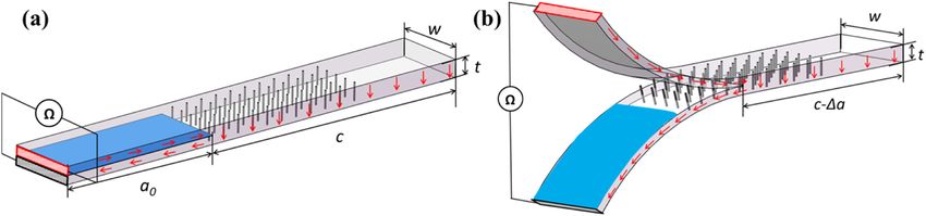
424 Zhe Che et al.
are increased to 1,981 and 1,902 J/m2 from 397 J/m2 for the
control sample. The debonding and pull-out of the
z-pins dominate the improvement of the interlaminar
fracture toughness. A strong interface is formed between
the z-pin and the surrounding laminate. The interfacial
shear failure load of a single z-pin is 46.5 N. Moreover,
the method of in situ damage monitoring via electrical
resistance measurement was established. The two dif-
ferent crack growth ways, stable crack growth in the con-
trol sample and stick-slip crack propagation in z-pinned
composites, are clearly reflected by the electrical resis-
tance curve. Z-pins enhance the sensitivity of delamina-
tion detection. The ΔR/R0 values of CCF300 and CCF800
z-pinned composites are increased to 9.1 and 14.3% from
5.9% of the control sample. The quantitative relationship
Figure 11: The relationship between ΔR/R0 and the crack length for between the crack length and the electrical resistance
control, CCF300, and CCF800 z-pinned composite. change of the DCB specimen was also established. The
direct reflection of the crack growth process develops a
CCF800 z-pinned composites show obvious crack propa- convenient way for the delamination failure analysis of
gation and retention processes. These crack growth pro- composites.
cesses correspond with the jagged load–displacement
curve. The load is increased when the crack length Acknowledgements: The authors acknowledge the sup-
slightly increases, and then the load is dropped sharply port of the Program for New Century Excellent Talents
as the crack propagates rapidly. The amplitude of sharp (NCET-11-0767) in the University.
load reductions is positively correlated with the rapid
crack propagation lengths. The crack growth status is Author contributions: Zhe Che: Methodology, Data cura-
accurately correlated with the load–displacement curve tion, Writing-Original draft preparation. Han Wang: Formal
by monitoring the resistance change, which provides a analysis. Shaokai Wang: Writing-Reviewing and Editing,
convenient method to calculate GIC and analyze the crack Resources. Yizhuo Gu: Validation. Min Li: Supervision,
growth process of the DCB specimen. Funding acquisition, Conceptualization. All authors read
Figure 11 shows the relationship between ΔR/R0 and and contributed to the manuscript.
the crack length during the DCB test for control and
z-pinned composites. The ΔR/R0 values increase with Conflict of interest: The authors state no conflict of
the increase of crack length for all three samples, and interest.
the increasing rate of ΔR/R0 value with crack length
becomes bigger. When the crack propagates to 110 mm, Data availability statement: The data presented in this
ΔR/R0 values of CCF300 and CCF800 z-pinned compo- study are available on request from the corresponding
sites are increased to 9.1 and 14.3%, which is much author.
higher than the ΔR/R0 value of 5.9% for the control
sample. These results demonstrate that z-pins greatly
enhance the interlaminar performance and improve the
sensitivity of damage detection.
References
[1] Hamer S, Leibovich H, Intrater R, Zussman E, Sherman D. Mode
4 Conclusion I interlaminar fracture toughness of Nylon 66 nanofibrilmat
interleaved carbon/epoxy laminates. Polym Compos.
2011;32(11):1781–9.
This article successfully fabricated z-pinned carbon fiber/
[2] Arai M, Hirokawa JI, Hanamura Y, Ito H, Hojo M, Quaresimin M.
epoxy composites by using CCF300 and CCF800 carbon Characteristic of mode I fatigue crack propagation of CFRP
fiber pins. The values of the mode I interlaminar fracture laminates toughened with CNF interlayer. Compos Part B.
toughness of the CCF300 and CCF800 z-pinned composites 2014;65:26–33.Delamination properties and in situ damage monitoring of composites 425
[3] Wang J, Ma C, Chen G, Dai P. Interlaminar fracture toughness using carbon nanofibres and z-pins. Compos Sci Technol.
and conductivity of carbon fiber/epoxy resin composite lami- 2016;131:98–109.
nate modified by carbon black-loaded polypropylene non- [23] Virakthi A, Kwon S, Lee S, Robeson M. Delamination resistance of
woven fabric interleaves. Compos Struct. 2020;234:111649. composite laminated structures reinforced with angled, threaded,
[4] An WJ, Kim CH, Choi JH, Kweon JH. Static strength of RTM and anchored z-pins. J Compos Mater. 2018;53:1507–19.
composite joint with I-fiber stitching process. Compos Struct. [24] M’Membe B, Yasaee M, Hallett S, Partridge I. Effective use of
2019;210:348–53. metallic z-pins for composites’ through-thickness reinforce-
[5] Ahmed S, Zheng X, Zhang D, Yan L. Impact response of carbon/ ment. Compos Sci Technol. 2019;175:77–84.
kevlar hybrid 3D woven composite under high velocity impact: [25] Pingkarawat K, Mouritz AP. Comparative study of metal and
experimental and numerical study. Appl Compos Mater. composite z-pins for delamination fracture and fatigue strength-
2020;27(3):1–21. ening of composites. Eng Fract Mech. 2016;154:180–90.
[6] Bilisik K, Sapanc E, Karaduman NS. Flexural characterization [26] Zhang Y, Wang S, Zhao X, Wang F, Wu G. In situ study on
of 3D prepreg/stitched carbon/epoxy/multiwall carbon fracture behavior of z-pinned carbon fiber-reinforced alu-
nanotube preforms and composites. J Compos Mater. minum matrix composite via scanning electron microscope
2018;53:5. (SEM). Materials. 2019;12(12):1941.
[7] Grassi M, Zhang X, Meo M. Prediction of stiffness and stresses [27] Bolotin VV. Delaminations in composite structures: Its origin,
in z-fibre reinforced composite laminates. Compos Part A Appl buckling, growth and stability. Compos Part B Eng.
Sci Manuf. 2002;33(12):1653–64. 1996;27(2):129–45.
[8] Mouritz AP, Chang P. Tension fatigue of fibre-dominated and [28] Gros XE, Ogi K, Takahashi K. Eddy Current, Ultrasonic c-scan
matrix-dominated laminates reinforced with z-pins. Int J and scanning acoustic microscopy testing of delaminated
Fatigue. 2010;32(4):650–8. quasi-isotropic CFRP materials: a case study. J Reinf Plast
[9] Mouritz AP. Compression properties of z-pinned composite Compos. 1998;17:389–405.
laminates. Compos Sci Technol. 2007;67(15–16):3110–20. [29] Xu D, Liu PF, Chen ZP, Li JG, Wang LL. Delamination analysis of
[10] Chang P, Mouritz AP, Cox BN. Flexural properties of carbon fiber/epoxy composite laminates under different
z-pinned laminates. Compos Part A Appl Sci Manuf. loading rates using acoustic emission. J Fail Anal Prev.
2007;38(2):244–51. 2019;19(11):1034–42.
[11] Chang P, Mouritz AP, Cox BN. Properties and failure mechan- [30] Pegorin F, Pingkarawat K, Mouritz AP. Electrical-based dela-
isms of z-pinned laminates in monotonic and cyclic tension. mination crack monitoring in composites using z-pins.
Compos Part A Appl Sci Manuf. 2006;37(10):1501–13. Compos Part A Appl Sci Manuf. 2018;104:120–8.
[12] Mouritz AP, Chang P, Isa MD. z-pin composites: aerospace [31] Zhang H, Liu Y, Kuwata M, Bilotti E, Peijs T. Improved fracture
structural design considerations. J Aerosp Eng. toughness and integrated damage sensing capability by spray
2011;24(4):425–32. coated CNTs on carbon fibre prepreg. Compos Part A Appl Sci
[13] Mouritz AP. Review of z-pinned laminates and sandwich Manuf. 2015;70:102–10.
composites. Compos Part A Appl Sci Manuf. 2020;139:106128. [32] Shen L, Liu L, Wang W, Zhou Y. In situ self-sensing of dela-
[14] Mouritz AP. Review of z-pinned composite laminates. Compos mination initiation and growth in multi-directional laminates
Part A Appl Sci Manuf. 2007;38(12):2383–97. using carbon nanotube interleaves. Compos Sci Technol.
[15] Dai S-C, Yan W, Liu H-Y, Mai Y-W. Experimental study on z-pin 2018;167:141–7.
bridging law by pullout test. Compos Sci Technol. [33] Zhang B, Allegri G, Hallett SR. An experimental investigation
2004;64(16):2451–7. into multi-functional z-pinned composite laminates. Mater
[16] Li C, Wu Z, Meng Z, Li M. Influential factors of z-pin bridging Des. 2016;108:679–88.
force. Appl Compos Mater. 2014;21(4):615–31. [34] Zhang B, Allegri G, Yasaee M, Hallett SR, Partridge IK. On the
[17] Knaupp M, Scharr G. Manufacturing process and performance delamination self-sensing function of z-pinned composite
of dry carbon fabrics reinforced with rectangular and circular laminates. Compos Sci Technol. 2016;128:138–46.
z-pins. J Compos Mater. 2013;48(17):2163–72. [35] Mouritz AP, Koh TM. Re-evaluation of mode I bridging traction
[18] Cartié D, Partridge IK. Delamination behaviour of z-pinned modelling for z-pinned laminates based on experimental
laminates. Eur Struct Integr Soc. 1999;27:27–36. analysis. Compos Part B Eng. 2014;56(Jan):797–807.
[19] Cartié DDR, Troulis M, Partridge IK. Delamination of z-pinned [36] Rausch J, Maeder E. Health monitoring in continuous glass
carbon fibre reinforced laminates. Compos Sci Technol. fibre reinforced thermoplastics: Tailored sensitivity and cyclic
2006;66(6):855–61. loading of CNT-based interphase sensors. Compos Sci
[20] Partridge IK, Cartié DDR. Delamination resistant laminates by Technol. 2010;70(13):2023–30.
z-fiber® pinning: Part I manufacture and fracture perfor- [37] Gao L, Thostenson ET, Zhang Z, Chou TW. Sensing of damage
mance. Compos Part A Appl Sci Manuf. 2005;36(1):55–64. mechanisms in fiber-reinforced composites under cyclic
[21] Kravchenko SG, Kravchenko OG, Carlsson LA, Pipes RB. loading using carbon nanotubes. Adv Funct Mater.
Influence of through-thickness reinforcement aspect ratio on 2009;19(1):123–30.
mode I delamination fracture resistance. Compos Struct. [38] Du X, Zhou H, Sun W, Liu H-Y, Zhou G, Zhou H, et al. Graphene/
2015;125:13–22. epoxy interleaves for delamination toughening and monitoring
[22] Ladani RB, Ravindran AR, Wu S, Pingkarawat K, Kinloch AJ, of crack damage in carbon fibre/epoxy composite laminates.
Mouritz AP, et al. Multi-scale toughening of fibre composites Compos Sci Technol. 2017;140:123–33.You can also read