Investigation by STEM-EELS of helium density in nanobubbles formed in aged palladium tritides
←
→
Page content transcription
If your browser does not render page correctly, please read the page content below
Investigation by STEM-EELS of helium density in
          nanobubbles formed in aged palladium tritides
      Bérengère Evin, E Leroy, M. Segard, Valérie Paul-boncour, S. Challet, A.
                                        Fabre, M. Latroche

     To cite this version:
    Bérengère Evin, E Leroy, M. Segard, Valérie Paul-boncour, S. Challet, et al.. Investigation by STEM-
    EELS of helium density in nanobubbles formed in aged palladium tritides. Journal of Alloys and
    Compounds, Elsevier, 2021, 878, pp.160267. �10.1016/j.jallcom.2021.160267�. �hal-03279753�

                                 HAL Id: hal-03279753
                https://hal.archives-ouvertes.fr/hal-03279753
                                     Submitted on 6 Jul 2021

    HAL is a multi-disciplinary open access            L’archive ouverte pluridisciplinaire HAL, est
archive for the deposit and dissemination of sci- destinée au dépôt et à la diffusion de documents
entific research documents, whether they are pub- scientifiques de niveau recherche, publiés ou non,
lished or not. The documents may come from émanant des établissements d’enseignement et de
teaching and research institutions in France or recherche français ou étrangers, des laboratoires
abroad, or from public or private research centers. publics ou privés.
                                              Copyright
Investigation by STEM-EELS of helium density in nanobubbles

formed in aged palladium tritides

B. Evina, E. Leroyb, M. Segarda, V. Paul-Boncourb, S. Challeta, A. Fabrea, M. Latrocheb

a
    CEA Valduc, F-21120, Is-sur-Tille, France

b
    Univ Paris-Est Creteil, CNRS, ICMPE (UMR 7182), 2 rue Henri Dunant, F-94320 Thiais,

France

E-mail adresses :

berengere.evin@icmpe.cnrs.fr,                                         leroy@icmpe.cnrs.fr,

mathieu.segard@cea.fr,paulbon@glvt-cnrs.fr, sylvain.challet@cea.fr, arnaud.fabre@cea.fr,

latroche@icmpe.cnrs.fr

Corresponding author :

Bérengère Evin (berengere.evin@icmpe.cnrs.fr)

Phone number : (+33) 149781214

Postal adress : ICMPE-CNRS, 2-4 rue Henri Dunant, 94320 Thiais, France

Keywords : palladium tritide, nanobubble pressure, helium-3, STEM-EELS

ABSTRACT

3
    He nanobubbles created by radioactive decay of tritium in palladium tritide are

investigated after several years of aging. Scanning Transmission Electron Microscopy –

Electron Energy-Loss Spectroscopy (STEM-EELS) has been used to measure helium

                                                1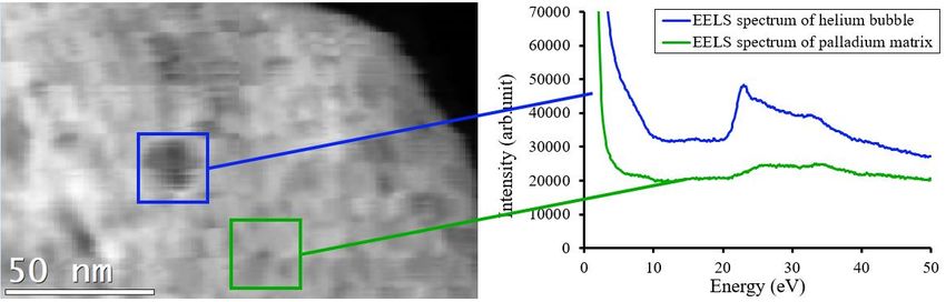
density from the helium K-edge around 23 eV. Helium densities were found between 20
and 140 (30) He/nm3 and the corresponding nanobubble pressures range between 0.1 and
3 (0.2) GPa. Measuring helium density and mapping He atoms by STEM-EELS enables to
differentiate bubbles from empty cavities in the palladium tritide matrix.
1. INTRODUCTION
Tritium is of notable interest due to its important role in nuclear industry. Before use,
this gas must be safely handled and stored. Hydrogen (or deuterium) gas storage is
commonly done by using pressurized tanks but tritium, as a radioactive element, is
less compatible with high pressure storage. As a result, reversible solid-state storage
by forming metallic tritides (hydrides) at low equilibrium pressure is a suitable
solution to store tritium chemically and ensure safety.
Palladium and its alloys are frequently used as tritium storage materials because of
their fast kinetics and strong resistance to oxidation [1]. Tritium spontaneously
decays into helium-3 (3He) with a half-life decay t1/2 ≈ 12.3 years. Contrary to
3 3
tritium, He solubility in Pd-based alloys is very small. Consequently He
nanobubbles nucleate within the Pd matrix by a self-trapping process [2]. The
3
formation of He nanobubbles comes with the creation of defects like auto-
interstitial metal atoms, dislocation loops and dislocations that modify the structural,
microstructural, mechanical and thermodynamic properties of the metal
tritides [3],[4],[5] [6] [7]. A recent review on implanted 3He bubbles is available in
reference [8]. This phenomenon is commonly named the “aging” process.
2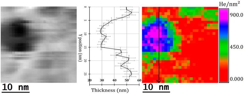
Palladium-based material aging has been studied at different scales using
complementary methods. Correlations between macroscopic mechanical studies and
Transmission Electron Microscopy (TEM) measurements show that the Young
modulus growth stops after one week whereas 3He bubble density stabilizes after the
first month of aging [9]. The knowledge of the distribution of the 3He nanobubbles in
the aged material is of noteworthy interest to better understand the modification of
the metal tritides properties. The material modification and evolution during aging is
calculated using a model that requires experimental input data [10].
After 1 to 3 months of aging in Pd, TEM studies have revealed that 3He bubbles have
a mean diameter of 1 nm and are uniformly distributed [11],[12]. For longer aging
time (8 months to several years), the 3He bubble diameters vary between 1 and
25 nm with a distribution centered around 2 nm [13] [14]. The mean bubble size
does not evolve too much after few months of aging.
Beside bubble size and density, 3He pressure inside the nanobubbles is also an
important parameter for modelling. Nuclear Magnetic Resonance (NMR) [15] or
Scanning Transmission Electron Microscopy – Electron Energy-Loss Spectroscopy
(STEM-EELS) [16] data can be used to calculate the 3He bubbles pressures. NMR
gives access to the average pressure of the whole bubble population by following the
rigid-fluid transition of 3He, for which the temperature depends on the pressure [17].
Complementarily, STEM-EELS allows for the local probe the pressure inside an
individual bubble by following the 1s 2p transition of 3He. In the present work,
3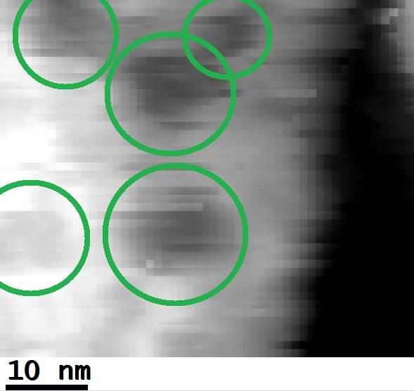
this last technique is used to characterize Pd powders with different aging time and
to determine the 3He pressure in the nanobubbles as a function of their size.
STEM-EELS allows the combination of both acquisitions imaging and spectroscopy
modes. STEM is a structural measurement that enables to observe bubbles and
determine their size whereas EELS is a quantitative way giving information on the
He density. Indeed, He free atoms exhibit a 1s 2p transition around 21.2 eV [18].
Walsh et al. proposed a method to calculate He density in a nanobubble based on the
blueshift of this transition [16]. He density inside the cavities can also be determined
by the intensity of the transition peak.
He density in bubbles was measured using this procedure for several materials,
mostly obtained by He implantation. David et al. evidenced the impact of residence
time on He density in nanobubbles implanted in semiconductor (silicon and
germanium) matrix. Bubbles between 5 and 25 nm in diameter show densities from
80 to 110 He/nm3 corresponding to pressures between 2 and 6 GPa [19]. Lacroix et
al. used spatially resolved EELS to investigate He -filled pores in cobalt created by
magnetron sputtering with nanopore sizes ranging from 4 to 20 nm [20]. He densities
range between 10 and 100 He/nm3 for pressures of 0.05 to 5.0 GPa. The authors also
observed the weaker He transition 1s 3p around 25 eV [20]. Blackmur et al.
mapped the association of hydrogen close to implanted He bubbles surface (between
1 and 10 nm diameter) in zirconium. In addition, halos were seen at 13.5 eV in the
EELS data around the bubbles and were attributed to hydrogen [21].
Taverna et al. used STEM-EELS to study He nanobubbles (diameter from 2 to
25 nm) within bulk Pd90Pt10 alloy aged for 8 months under tritium [13]. He densities
4range from 15 to 35 He/nm3 corresponding to pressure between 0.1 and 0.3 GPa. He
peak shift was also studied, and a linear relationship between blueshift and He
density was obtained. Overall, for all these nanobubbles the order of magnitude
expected for the pressure is close to GPa. All the quoted works are consistent with
the theoretical trend: the pressure decreases with increasing the bubble diameter
(Laplace’s law : P=2/r, with P the pressure, the surface tension and r the bubble
radius).
Complementary to these previous works, the present investigation focusses on the
3
identification and characterization of He nanobubbles obtained by tritium
radioactive decay in Pd powders with longer aging times (several years). Spatially
resolved Electron Energy Loss Spectroscopy has been used to measure and map 3He
density and the corresponding pressure for two samples that are several years old.
2. EXPERIMENTAL METHODS
2. 1. Samples preparation
Palladium powder samples (mean aggregates size about 14 µm, mean particle size
between 0.2 and 1 µm) were cleaned up by deuterium absorption–desorption cycles
before tritium loading, and were aged at room temperature. Pd powders were aged
during 6 to 8 years under tritium and have been maintained at a constant T/Pd ratio
during aging time The decontamination of Pd tritide powders is realized by isotopic
exchange with deuterium in -phase.
To characterize the aging of the materials, the ratio between 3He and metal atoms
(He/M) was used. It is calculated using the tritide stoichiometry and the aging time.
5In the present work, measurements were performed on two samples with He/Pd
ratios of 0.23 and 0.27 as they contain large 3He bubbles [14]. Their close aging time
implies that no large difference is expected between these two samples, but it allows
checking the reproducibility of the results from one sample to another.
The powders were embedded in an epoxy resin. Samples were cut using
ultramicrotomy at room temperature with a diamond knife and deposited on a
400 mesh copper grid. Before TEM observations, the sample surface was cleaned in
an O2/H2 plasma in order to remove the carbonated contamination.
2. 2. STEM-EELS characterization
The experiments were conducted in a FEI TECNAI F20 G2 microscope operated at
200 kV. The STEM-EELS acquisitions were recorded through a GATAN GIF 2001
with the following experimental parameters: 1024 channels, energy dispersion of
0.1 eV/channel, integration time of 0.1 s, pixel size ranging from 1 to 2 nm, energy
resolution of 1.4 eV, convergence and collection angles of 17 mrad and 5.86 mrad
respectively, beam current of the electron probe of 9.87 nA and probe size of 1 nm.
The acquisition time was optimized to maximize the 3He K-edge signal, avoid
sample drifting and avoid 3He detrapping from nanobubbles. Simultaneously, High
Angle Annular Dark Field (HAADF) images of the STEM-EELS investigated area
were recorded. The mean free path is around 100 nm.
Moreover, to reduce the probability of 3He detrapping and enhance the sample
stabilization under the electron beam, all the experiments were conducted at
temperatures ranging from 101 K to 141 K with a GATAN double tilt nitrogen
6cooling sample holder model 636. Liquid nitrogen cooling was efficient in reducing
3
He detrapping and in slowing carbon contamination. These observations were made
after conducting first STEM-EELS attempts at room temperature. Measurements at
101K showed no helium detrapping after twelve acquisitions on the same bubble.
This phenomenon was also reported in reference [22] and linked to long time scale
relaxation phenomenon.
3. RESULTS AND DISCUSSION
3. 1. Data analysis
3. 1. 1. TEM Imaging
In this study, « cavity » refers to any cavity filled or not with 3He whereas « bubble »
stands for 3He-filled cavity by opposition to « empty cavity ». TEM imaging was
performed to measure the cavity number and diameters for several palladium tritide
grains. Under-focused (-1 m) images reveal cavities as white dots and over-focused
(+1 m) images as black dots as seen in Figure 1. The cavity surface density is
measured using the maximum search of the ImageJ software and is combined with
the sample thickness measured by EELS (see Supplementary Materials 5 and 6) to
obtained the cavity volume density in the material (in cavity/m 3). The cavity
diameter is measured using the Feret’s diameter. For each sample, at least
3000 cavities are processed to build the statistics on cavity diameter and density.
7Figure 1 - Under (left) and over (right) focused TEM images acquired on two aged
palladium tritide grains with He/Pd=0.23.
In both samples (He/Pd = 0.27 and He/Pd = 0.23), the cavity diameters range
between 2 and 20 nm. The cavity size exhibits a log-normal distribution centered
around 2.5 nm and displays a mean value between 2.60.3 and 2.80.3 nm (see
Supplementary Materials 1). These cavity diameters are slightly larger than those
measured by Thiébaut et al. [11] (0.8 to 1 nm) for Pd alloys aged several months
compared to several years in this work. Cavity density ranges from 4.10 23 to
1.1024 cavity/m3 in the present samples. The cavity density obtained by Thiébaut et
al. was around 1025 bubble/m3, slightly higher but not far from the current results.
The discrepancy can be explained by the uncertainty in the determination of the
8sample thickness in reference [11]. Indeed, the cutting thickness was used to
calculate the cavity volume density. In the present study, the sample local thickness
was measured by EELS spectroscopy and used to calculate the cavity volume
density. The cutting thickness can be slightly different than the real local thickness
and its value will directly modify the cavity volume density.
3. 1. 2. Helium nanobubble EELS spectrum
In HAADF images, cavities appear as black dots in a light grey palladium matrix.
From extracted EELS spectra, the presence of 3He appears as a sharp peak around
23 eV attributed to the 3He K-edge (Figure 2). Besides 3He, Pd contribution appears
as a broad plasmon centered around 25 eV and spreading between 15 and 40 eV.
3
These different shapes between the EELS spectra of He and Pd allow clear
distinction between 3He nanobubbles from the Pd matrix (Figure 2 and 3).
Figure 2 - HAADF image (left), extracted EELS spectrum of helium bubble and Pd
matrix (top blue), extracted spectrum of Pd matrix (bottom green) acquired on aged
palladium tritide grains with He/Pd=0.27.
9Figure 3 - EELS spectra of Pd matrix (1), Pd matrix + He bubble with 1s2p
transition (2), Pd matrix + He bubble with 1s2p transition and 1s3p transition (3)
acquired on aged palladium tritide grains with He/Pd=0.23
Three different EELS spectra are presented in Figure 3: the red one is extracted from
the Pd matrix, the green and black ones arise from 3He nanobubbles. For the black
spectrum, beside the main 1s 2p He-K edge transition at 23 eV, a second peak
close to 25 eV is observed and attributed to the 1s3p He-K edge transition. This
weaker transition has also been reported by Blackmur et al. [21]. However, this side
peak is not always observed in our measurements.
In addition to the main peaks in Fig. 3, a small peak is also seen at 7 eV. It is
commonly attributed to surface interactions between the 3He bubbles and the matrix
10[19],[21]. This peak is usually better seen with EELS spectra extracted close to the
bubble edge.
Since 3He nanobubbles are included in a Pd matrix, the resulting EELS spectrum is
the sum of 3He and Pd energy-losses, 3He K-edge and Pd plasmon are then
overlapping.
3. 1. 3. Datacube treatment
The first step to process EELS spectra and to calculate 3He density consists in the
extraction of the 3He contribution by removing the palladium plasmon signal. Several
methods reported in the literature have been tested : spatial difference [21], Principal
Component Analysis (PCA, MVA…) and Gaussian adjustment [23]. The latter one was
found to be the best method to remove the Pd plasmonic contribution in our case (Figure 4).
11Figure 4 - EELS spectrum before (green square □) and after (blue circle ○)
subtraction of the Pd plasmonic contribution using Gaussian adjustment (red curve).
The refinement was done with a Gaussian like function, first by selecting points
before (15-20 eV) and after (30-45 eV) the 3He K-edge, and then extrapolating to the
entire range between 15 and 45 eV. This method correctly extracts the 3He peak as
shown in Figure 4.
3. 1. 4. Atomic density
The 3He density inside the bubbles was calculated using the helium 1s2p transition
and the following equation (1):
(1)
12nHe represents the helium volume density (in He/nm3), IHe is the integrated signal of
helium, IZLP the integrated intensity of the elastic peak (zero-loss peak), σHe the
cross-section (in nm²) and h the cavity thickness crossed by the electron beam (nm).
The convergence and collection angles were measured and are respectively 17.0 and
5.86 mrad. The cross-section σHe = 5.9.10-6 nm² was calculated using the Sigmak3 program
[24]. Since the sample mostly contains Pd, the absolute thickness of the sample is
calculated using the atomic number of Pd. However, this does not give the He thickness,
needed for the volume density calculation. An approximate He thickness can be obtained
using the projected diameter of the bubble.
The uncertainty associated with the bubble diameter is taken equal to the spatial resolution,
that is 1 nm. The cartography of the surface density is the result of calculation and post-
processing; its uncertainty is complex to evaluate. The penalizing choice of assimilating it
to the surface density which was sometimes observed on the areas of Pd matrix, where it
should be zero but due to treatment can reach 100 He/nm² was made (see Supplementary
Materials 3 and 4). These calculations lead to an average uncertainty of 30 He/nm3 that will
be used in this study. This leads to a pressure uncertainty of 0.2 GPa.
3. 1. 5. Helium density mapping
Once the He peak is isolated in EELS spectra, He volume density is determined
using equation (1). This equation is implemented in a homemade Digital Micrograph
script to map 3He surface density on the surveyed area of the sample as seen in
Figure 5. STEM-EELS data in Figure 5 were recorded at 101 K.
13Figure 5 - 1) HAADF image (top-left) 2) EELS signal between 22 and 25 eV (top-right)
3) EELS signal between 22 and 25 eV after data treatment (bottom-left) 4) Helium
surface density map calculated in He/nm² (bottom-right) for aged palladium tritide
grains with He/Pd=0.27. All images were recorded at 101 K.
The white pixels in Figure 5-2 represent the high intensity EELS signal between 22
and 25 eV and are consistent with the black areas shown in HAADF image, Figure
5-1 allowing the identification of 3He bubbles. Subtraction of the Pd plasmon
contribution (Figure 5-3) enhances the contrast of the EELS signal between bubbles
and Pd. Finally, the 3He mapping in He/nm² shown in Figure 5-4 enables the easy
identification of areas of high 3He concentrations, i.e. 3He nanobubbles. The ratio
between the helium density mapped in He/nm² and the diameter of the bubble allows
14determination of the helium density in He/nm3. It is also worthwhile to note the
presence of black dots in the HAADF image that do not correspond to 3He bubbles
and are therefore interpreted as empty cavities. A 3He surface density (in He/nm²)
gradient is noticeable from the center to the edge of the main bubbles.
3. 2. Results
3. 2. 1. Multiple nanobubbles
The STEM-EELS acquisition was done close to one large bubble ( 11 nm) at
101 K. The HAADF image (Figure 6-left) reveals that the bubble might be the sum
of two overlapping bubbles as two darker spots are noticeable in the bubble.
Figure 6 - HAADF image (left), thickness profile (center) and helium surface density
map in He/nm² (right) of helium bubbles for aged palladium grains with He/Pd=0.27.
The thickness profile was measured along the black arrow shown on the right.
The 3He surface density (Figure 6-right) is higher at the center of the bubble (around
900 He/nm²) than at the edges (500 He/nm²). The mean density of the entire bubble
is around 600 He/nm². The ratio between the 3He projected density in He/nm² and
15the projected diameter of the bubble allows determination of the 3He volume density
in He/nm3. The mean density of the whole bubble is then 6030 He/nm3 which
corresponds to a pressure of 1.10.2 GPa. For the two smaller bubbles that seem
included in the large one, the densities are 14030 He/nm3 (top bubble) and
20030 He/nm3 (bottom bubble). Since bubble pressure (or density) is expected to
increase with decreasing diameter, this last result is not surprising. This inverse
proportional relation between pressure and radius following Laplace’s law was
reported in reference [13].
A thickness profile of the Pd sample (Figure 6-center) was extracted along the black arrow
shown on the 3He density map (Figure 6-right). The sharp decrease of the thickness from
50 nm to 30 nm confirms the presence of a bubble. Since the projected diameter of the
whole bubble is 11 nm, the 20 nm thickness drop favors the assumption of overlapped
bubbles. Moreover, the slight increase from 30 to 35 nm at the center of the bubble supports
the hypothesis of two overlapped bubbles in the thickness of the sample. Nevertheless,
EELS spectroscopy gives only a 2D projected information from a 3D sample, it is then
difficult to discriminate between one or two bubbles. This issue could be solved by tilting
the sample to obtain spatial information by tomography, but this is out of the scope of this
paper.
3. 2. 2. Empty cavities
At the beginning of this section, the difference between empty cavity and bubble was
made. Figure 7 illustrates this case for a sample with He/Pd = 0.27, in which the
HAADF image shows five dark circular spots.
16Figure 7 - HAADF image (left) with cavities circled in green and helium density map
in He/nm² (right) of helium bubble and empty cavity for aged palladium tritide grains
with He/Pd=0.27.
The HAADF image (Figure 7 left) shows five cavities of similar morphology seen as
large black circular dots circled in green. HAADF intensity profile is available in
Supplementary Materials 7. However, the 3He density map (Figure 7 right) only
reveals 3He in two cavities. The other three cavities are either empty or have too low
pressure to observe He. The 3He density of the left bubble is 7530 He/nm3
corresponding to 1.70.2 GPa, and the density in the right bubble is 5030 He/nm3
corresponding to a pressure of 0.70.2 GPa.
3
He might have left the cavities during the EELS measurement due to interaction
with the electron beam. This phenomenon was quantified by David et al. and was
surprisingly fast in their case [19] [22]. This emptiness can also be explained by the
closeness between the cavity and the Pd surface or by some 3He departure during
sample preparation. Pre-existing cavities have been observed in hydrogenated Pd
17powders not aged under tritium (see Supplementary Materials 2). This might explain
the origin of some empty cavities.
Distinction between bubble and cavity illustrates the strength of EELS compared to
other analytical techniques. Indeed, TEM and SANS allow the identification of
cavities, whereas NMR can measure the mean He pressure in bubbles but does not
detect cavities.
3. 2. 3. Radial evolution of helium density
The radial evolution of 3He density from the center to the edge of the bubbles has been
studied for the largest ones in the samples.
Figure 8 - Radial evolution of helium density in He/nm3 in aged palladium tritide
grains with He/Pd=0.23 and 0.27.
For all bubbles, 3He surface density decreases slightly as the value is taken far from the
center of the bubble. This gradient of density in He/nm² is seen on bubbles taken from
18Figure 6 and 7. This tendency is related to the fact that the beam encounters less 3He atoms
at the edge of the bubbles, however this effect remains small except for the 17nm bubble.
This small effect supports the assimilation of 3He thickness with the cavity diameter.
3. 2. 4. Density-Pressure-Diameter relationship
From all studied samples, the 3He density range was established between 20 and
14030 He/nm3 with an average density of 7030 He/nm3. From 3
He density,
pressure was calculated using semi-empirical equation of state (EOS) of helium-4
assuming that there is no isotopic effect between 3He and 4He. The analytical
expression of the EOS was extracted from references [19] and [25] for high and low
densities (under/over 140 He/nm3 respectively).
Figure 9 - Helium pressure as a function of bubble diameters in aged palladium tritide
grains with He/Pd = 0.23 and 0.27.
19As seen in Figure 9, the 3He pressure ranges from 0.1 to 3 0.2 GPa for bubbles
ranging from 17 to 5 nm, the average pressure being 1.10.2 GPa. The pressure
tends to decrease when the bubble diameter increases, as predicted by the Laplace’s
law. The pressure values found in the 3He bubbles agree with previous works.
Taverna et al. found pressures ranging from 0.1 to 0.3 GPa for bubbles of 17 to
5 nm, respectively in bulk Pd-Pt alloy [13]. David et al. found pressures ranging
from 2 to 6 GPa for bubbles from 25 to 6 nm in silicon [19].
The bubble pressure is a key parameter calculated by modelling the bubble growth
mechanism in metallic tritide, based on continuum mechanics [10]. The order of
magnitude of the pressure provided by the model is a few GPa, in good agreement
with the pressures determined by STEM-EELS. The experimental bubble pressure
determinations enhance the confidence in the theoretical model.
Mean helium pressure estimated by NMR in aged Pd sample was estimated around
several GPa for a transition temperature of 250 K [15] [26] [27]. The combination of
these previous NMR results and this EELS study strengthens the confidence placed
in the theoretical results provided by the mechanical model (bubble pressure of
several GPa). Further works will be performed with samples having similar He/Pd
rate and measurements will be done at liquid He temperature to compare EELS and
NMR techniques. In addition, the difference between values from EELS and NMR
can be explained by the size of the bubbles. By EELS analyses, a focus is made on
the largest bubbles ( > 5 nm) whereas NMR gives an average value including
20smaller bubbles. Since mean diameter of the samples is 2.6 nm, pressure obtained by
EELS on large bubbles may be under the average value of the samples.
4. CONCLUSION
3
He nanobubbles created by radioactive decay of tritium in palladium tritide powders
were successfully characterized by STEM-EELS. HAADF imaging led to the
localization of the cavities within the Pd matrix, whereas EELS spectroscopy
allowed the identification and quantification of 3He bubbles.
Data treatment (data post-processing and use of a homemade script) of the EELS
spectra allows the extraction of the 3He contribution from the Pd signal and the
mapping of the 3He density in the surveyed areas. The 3He densities, ranging
between 20 and 14030 He/nm3, agree with previous studies. For 3He nanobubbles
from 5 to 17 nm diameter, the 3He pressures decrease from 3 to 0.10.2 GPa.
Those pressures determinations enhance the confidence in the theoretical mechanical
model of helium bubble growth that provides bubble pressures of a few GPa.
Mapping 3He density in He/nm² reveals that 3He surface density decreases from the
center to the edge of the bubbles. This tendency is consistent with the fact that the
electron beam encounters more 3He atoms at the center of the bubble.
3
The STEM-EELS measurements enable to better characterize the He bubbles
3
observed by TEM. By measuring He density and pressure, it is possible to
discriminate between bubbles and empty cavities. Some interactions between the
electron beam and 3He atoms were observed, which can induce 3He diffusion and
detrapping.
21Further investigations with STEM-EELS on 3He bubbles will focus on spatial
resolution and thickness evaluation that will be enhanced by calculating the number
of missing metal atoms [13],[19]. Moreover, samples with different aging times will
be studied. To improve further the knowledge on 3He nanobubbles and Pd tritide
aging, next work will focus on 3D characterizations using electron tomography.
FUNDINGS
This work was supported by the France’s Atomic Energy Commission (C.E.A.) and
by the French National Center for Scientific Research (C.N.R.S.).
REFERENCES
[1] R. Lässer, Properties of tritium and 3He in metals, J. Common Met. 131 (1987) 263–
273. https://doi.org/10.1016/0022-5088(87)90525-X.
[2] W.D. Wilson, C.L. Bisson, M.I. Baskes, Self-trapping of helium in metals, Phys. Rev.
B. 24 (1981) 5616. https://doi.org/10.1103/PhysRevB.24.5616.
[3] V. Paul-Boncour, S. Thiébaut, B. Limacher, A. Percheron Guégan, Study of the
defects induced by 3He in Pd and LaNi5 tritides, Rev. Métallurgie Cah. Inf. Tech.
(1999) 1073–1078.
[4] S. Thiébaut, V. Paul-Boncour, A. Percheron-Guégan, B. Limacher, O. Blaschko, C.
Maier, C. Tailland, D. Leroy, Structural changes in Pd (Rh, Pt) solid solutions due to
3He formation during tritium storage, Phys. Rev. B. 57 (1998) 10379–10387.
https://doi.org/10.1103/PhysRevB.57.10379.
[5] S. Thiébaut, J. Demoment, B. Limacher, V. Paul-Boncour, B. Décamps, A. Percheron-
Guégan, M. Prem, G. Krexner, Aging effects on palladium pressure–composition
isotherms during tritium storage, J. Alloys Compd. 356–357 (2003) 36–40.
https://doi.org/10.1016/S0925-8388(03)00097-5.
[6] S. Thiébaut, M. Douilly, S. Contreras, B. Limacher, V. Paul-Boncour, B. Décamps, A.
Percheron-Guégan, 3He retention in LaNi5 and Pd tritides: Dependence on
stoichiometry, 3He distribution and aging effects, J. Alloys Compd. 446–447 (2007)
660–669. https://doi.org/10.1016/j.jallcom.2007.01.041.
[7] M. Prem, G. Krexner, J. Pleschiutschnig, Helium damage in long-aged metal–tritium
systems, J. Alloys Compd. 356–357 (2003) 683–687. https://doi.org/10.1016/S0925-
8388(02)01290-2.
22[8] S.-H. Li, J.-T. Li, W.-Z. Han, Radiation-Induced Helium Bubbles in Metals,
Materials. 12 (2019) 1036. https://doi.org/10.3390/ma12071036.
[9] A. Fabre, B. Decamps, E. Finot, J.M. Penisson, J. Demoment, S. Thiebaut, S.
Contreras, A. Percheron-Guegan, On the correlation between mechanical and TEM
studies of the aging of palladium during tritium storage, J. Nucl. Mater. 342 (2005)
101–107. https://doi.org/10.1016/j.jnucmat.2005.02.011.
[10] F. Montheillet, D. Delaplanche, A. Fabre, E. Munier, S. Thiébaut, A mechanical
analysis of metallic tritide aging by helium bubble growth, Mater. Sci. Eng. A. 494
(2008) 407–415. https://doi.org/10.1016/j.msea.2008.04.033.
[11] S. Thiébaut, B. Décamps, J.M. Pénisson, B. Limacher, A. Percheron Guégan, TEM
study of the aging of palladium-based alloys during tritium storage, J. Nucl. Mater.
277 (2000) 217–225. https://doi.org/10.1016/S0022-3115(99)00191-9.
[12] G.J. Thomas, J.M. Mintz, Helium bubbles in palladium tritide, J. Nucl. Mater. 116
(1983) 336–338. https://doi.org/10.1016/0022-3115(83)90124-1.
[13] D. Taverna, M. Kociak, O. Stéphan, A. Fabre, E. Finot, B. Décamps, C. Colliex,
Probing Physical Properties of Confined Fluids within Individual Nanobubbles, Phys.
Rev. Lett. 100 (2008) 035301. https://doi.org/10.1103/PhysRevLett.100.035301.
[14] M. Segard, E. Leroy, TEM observations of palladium aged under tritium, Materiala.
(2021) revision.
[15] G.C. Abell, A. Attalla, NMR evidence for solid-fluid transition near 250 K 3He
bubbles in palladium tritide, Phys. Rev. Lett. 59 (1987) 995.
https://doi.org/10.1103/PhysRevLett.59.995.
[16] C.A. Walsh, J. Yuan, L.M. Brown, A procedure for measuring the helium density and
pressure in nanometre-sized bubbles in irradiated materials using electron-energy-loss
spectroscopy, Philos. Mag. A. 80 (2000) 1507–1543.
https://doi.org/10.1080/01418610008212134.
[17] G.C. Abell, A. Attala, NMR Studies of aging effects in Palladium Tritide, Fusion
Technol. 14 (1988) 643–648.
[18] J.C. Rife, S.E. Donnelly, A.A. Lucas, J.M. Gilles, J.J. Ritsko, Optical Absorption and
Electron-Energy-Loss Spectra of Helium Microbubbles in Aluminum, Phys. Rev.
Lett. 46 (1981) 1220–1223. https://doi.org/10.1103/PhysRevLett.46.1220.
[19] M.-L. David, K. Alix, F. Pailloux, V. Mauchamp, M. Couillard, G.A. Botton, L.
Pizzagalli, In situ controlled modification of the helium density in single helium-filled
nanobubbles, J. Appl. Phys. 115 (2014) 123508. https://doi.org/10.1063/1.4869213.
[20] B. Lacroix, V. Godinho, A. Fernández, The nanostructure of porous cobalt coatings
deposited by magnetron sputtering in helium atmosphere, Micron. 108 (2018) 49–54.
https://doi.org/10/gdhxch.
[21] M.S. Blackmur, S. Dumbill, I. MacLaren, D. Hernandez-Maldonado, P.D. Styman, M.
Gass, R.J. Nicholls, J.M. Hyde, Q.M. Ramasse, K.J. Annand, J.S. Smith, N. Gotham,
The association of hydrogen with nanometre bubbles of helium implanted into
zirconium, Scr. Mater. 152 (2018) 102–106.
https://doi.org/10.1016/j.scriptamat.2018.04.007.
[22] M.-L. David, F. Pailloux, V. Mauchamp, L. Pizzagalli, In situ probing of helium
desorption from individual nanobubbles under electron irradiation, Appl. Phys. Lett.
98 (2011) 171903.
23[23] F. Attouchi, Study by EELS of helium nanobubbles and gold-silver nanoparticles
(Au@Ag), PhD thesis, University Paris South - Paris XI, 2014.
[24] R.F. Egerton, Electron Energy-Loss Spectroscopy in the Electron Microscope Second
Edition, Plenum, 1996.
[25] H. Trinkaus, The effect of internal pressure on the coarsening of inert gas bubbles in
metals, Scr. Metall. 23 (1989) 1773–1778. https://doi.org/10.1016/0036-
9748(89)90359-1.
[26] G.C. Abell, D.F. Cowgill, Low-temperature 3He NMR studies in aged palladium
tritide, Phys. Rev. B. 44 (1991) 4178. https://doi.org/10.1103/PhysRevB.44.4178.
[27] D.F. Cowgill, Helium Nano-Bubble Evolution in Aging Metal Tritides, Fusion Sci.
Technol. 48 (2005) 539–544. https://doi.org/10.13182/FST48-539.
24You can also read