Concept study Extension of IO-Link for Single Pair Ethernet transmission - January 27, 2020 - IO-Link SPE
←
→
Page content transcription
If your browser does not render page correctly, please read the page content below
Concept study

Extension of IO-Link for
 Single Pair Ethernet
     transmission

                     Authors:
    Dmitry Gringauz (Banner Engineering Corp.)
              Frank Moritz (SICK AG)
     Hartmut Lindenthal (Pepperl+Fuchs AG)
     Dr. Franz-Otto Witte (TEConcept GmbH)

                Version V1.00

           January 27, 2020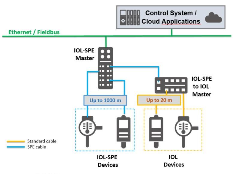
Concept study - IO-Link over SPE                                                                        Version 1.00
_____________________________________________________________________________________________________

File name: IO-Link_over_SPE_V100_Jan20

This document has been prepared by the IO-Link community.

Important notes:
NOTE 1 The IO-Link Community Rules shall be considered prior to the development and marketing of IO -Link
       products. The document can be downloaded from the www.io-link.com portal.

Disclaimer:
The attention of adopters is directed to the possibility that compliance with or adoption of IO -Link Community
   specifications may require use of an invention covered by patent rights. The IO -Link Community shall not be
   responsible for identifying patents for which a license may be requi red by any IO-Link Community specification,
   or for conducting legal inquiries into the legal validity or scope of those patents that are brought to its attention.
   IO-Link Community specifications are prospective and advisory only. Prospective users are res ponsible for
   protecting themselves against liability for infringement of patents.
The information contained in this document is subject to change without notice. The material in this document details
   an IO-Link Community specification in accordance with the license and notices set forth on this page. This
   document does not represent a commitment to implement any portion of this specification in any company's
   products.
WHILE THE INFORMATION IN THIS PUBLICATION        IS BELIEVED TO BE ACCURATE, THE IO-
  LINK COMMUNITY MAKES NO WARRANTY OF ANY KIND, EXPRESS OR IMPLIED, WITH REGARD TO THIS
  MATERIAL INCLUDING, BUT NOT LIMITED TO ANY WARRANTY OF TITLE OR OWNERSHIP, IMPLIED
  WARRANTY OF MERCHANTABILITY OR WARRANTY OF FITNESS FOR PARTICULAR PURPOS E OR USE.
In no event shall the IO-Link Community be liable for errors contained herein or for indirect, incidental,
   special, consequential, reliance or cover damages, including loss of profits, revenue, data or use, incurred
   by any user or any third party. Compliance with this specification does not absolve manufacturers of IO -
   Link equipment, from the requirements of safety and regulatory agencies (TÜV, BIA, UL, CSA, etc.).

            ® is a registered trademark. It may be used only by the members of the IO-Link
Community and non-members who had acquired the corresponding license. For more detailed
information on its use, refer to the rules of the IO -Link Community at www.io-link.com.

Publisher:
IO-Link Community
c/o PROFIBUS Nutzorganisation e.V.
Haid-und-Neu-Str. 7
76131 Karlsruhe
Germany
Phone: +49 721 / 96 58 590
Fax:    +49 721 / 96 58 589
E-mail: info@io-link.com
Web site: www.io-link.com

© No part of this publication may be reproduced or utilized in any form or by any means, electronic or
mechanical, including photocopying and microfilm, without permission in writing from the publisher.

_____________________________________________________________________________________________________

© Copyright IO-Link Community 2020 - All Rights Reserved                                                  Page   2 of 20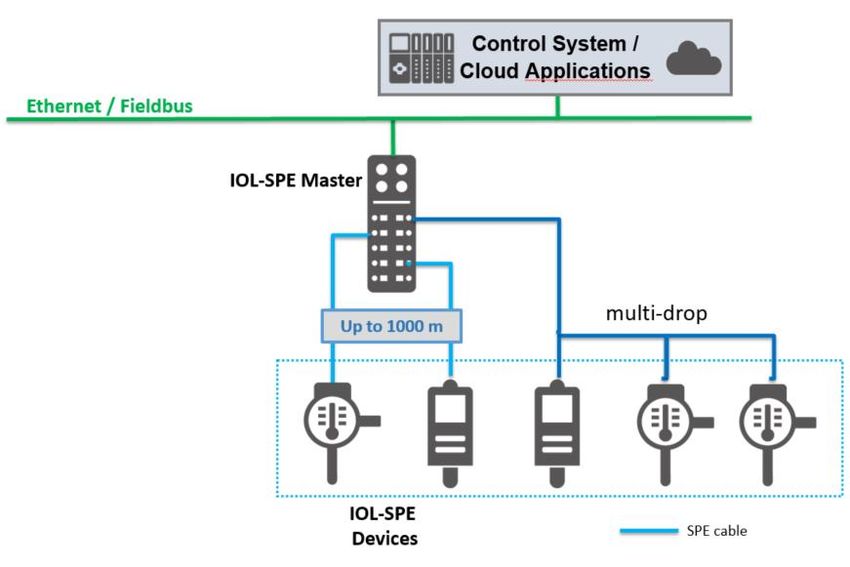
Concept study - IO-Link over SPE Version 1.00
_____________________________________________________________________________________________________
Abstract
The following study describes concepts for an integration of IO-Link communication over Single
Pair Ethernet (SPE) or Advanced Physical Layer (APL) technology. It describes advantages
and benefits of combining these technologies with IO-Link.
IO-Link is well known as an industrial communication interf ace designed mainly for factory
automation. It addresses the communication to field devices – sensors or actuators. W ith a
scalability of three different transmissions rates and a maximum cable length of 20 meters, IO-
Link already covers a wide range of the requirements of today’s automation applications.
Overall, the ease of integration into automation systems as well as the high degree of
standardization of common functionalities and device description are just two key benefits of
this communication technology.
Ethernet based communication is today a standard in automation. Most fieldbus standards are
using Ethernet for communication between control systems (PLCs) and field devices such as
discrete I/O aggregators (I/O blocks), high-end sensors, vision systems, actuators and motors.
Up to now, the cost, complexity and the lack of standardized power delivery have kept Ethernet
out of simple low-cost sensors.
The current standardization of SPE – Single Pair Ethernet – opens new possibilities as well for
industrial communication. The definition of the SPE-based APL – Advanced Physical Layer –
addresses the requirements for communication to field devices in process automation and
intrinsically safe areas.
Some of the key features of these technologies are:
IO-Link – Point-to-point topology
IO-Link – Simple installation using standard cables
IO-Link – Small footprint protocol without addressing
SPE – Communication and power supply via a twisted-pair cable
SPE – Cable lengths of up to 1000 m
SPE – Tolerance against reverse polarity
SPE – Connection via terminals or industrial connections
APL – Support for intrinsic safety applications for use in all regional markets
With the ongoing digitalization process in industry new requirements, arise for a wider variety
of field devices, more functionality and information as well as a broader field of application.
1 Proposed approach
Ethernet is a collection of networking technologies used to implement local area networks
(LANs) in industrial, business and home applications. It is standardized under the IEEE 802.3
family of standards.
Ethernet standards cover the lowest two layers of OSI model, Physical and Data Link layers.
One of Ethernet’s distinguished characteristics is a number of different physical la yers that all
utilize a common Data Link Layer protocol data unit, or frame. This approach permits backward
compatibility between new and old physical layers. With appropriate adaptations,
interoperability between Ethernet networks can be implemented between different physical
layers.
In Ethernet family of standards, physical layer implementation is often called a PHY.
1.1 Ethernet Physical layer
Early versions of Ethernet utilized a thick coaxial cable and ran at a speed of 2.5 Megabits per
second. As the technology evolved, new physical layers were incorporated into Ethernet
standard, such as thin coaxial cable and, eventually, a cable with four twisted pairs. For 10Mbps
and 100Mbps networks, four pairs are used: two to transmit data to the device and two to
receive data from the device. This allowed the device to transmit and receive data at the same
_____________________________________________________________________________________________________
© Copyright IO-Link Community 2020 - All Rights Reserved Page 3 of 20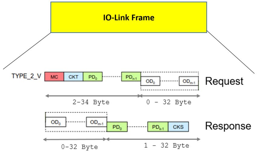
Concept study - IO-Link over SPE Version 1.00
_____________________________________________________________________________________________________
time by implementing a full-duplex connection. For 1000Mbps networks, all four pairs are used
to implement a full-duplex connection.
Coaxial cable-based systems shared a single cable among multiple devices and implemented
a frame collision detection and avoidance technique called CSMA/CD (Carrier Sense Multiple
Access/ Collision Avoidance) to avoid data corruption (frame collisions can occur when two
devices start transmitting at the same time). Twisted pair -based systems use switches and
point-to-point connections to implement networks with a more complicated star topology.
Twisted pair systems are considered collision-free, although they can experience data frame
loss in the switches under heavy load.
Ethernet physical layers are described in the form of abbreviation that lists the speed ,
transmission technology (baseband), maximum segment length and/or cable type. Some of the
physical layers defined by the standard are:
10Base5 – 10-megabit, baseband, coax cable, 500 meter length
10BaseT – 10-megabit, baseband, twisted pair
100BaseT – 100-megabit, baseband, twisted pair
1000BaseT – 1000-megabit, baseband, twisted pair
In addition to increased speed, some of the new physical layer implementations also provided
power delivery on the existing 4-pair cable. This technology is referred to as POE, or Power
over Ethernet. POE typically uses separate pairs within the same cable to transmit power and
data signals.
1.2 SPE – Single Pair Ethernet
SPE, or Single Pair Ethernet, is an up-and-coming Ethernet physical layer standard presently
under development which is standardized as the IEEE 802.3cg. It uses the same data frame
definition as all other standards in the 802.3 family but defines two new physical layers (PHYs):
10Base-T1L (long-reach)
10Base-T1S (short-reach)
APL (intrinsic safe)
SPE was conceived as a potential replacement for several slower -speed fieldbuses, such as
CAN, HART, MODBUS RTU and similar. It originated in the automotive industry and was
extended to accommodate industrial automation and building monitoring applications, hence
the introduction of two separate PHYs. One of the main goals of its introduction is to push
Ethernet all the way to the edge devices, therefore creating a more homogeneous automation
network.
1.2.1 10Base-T1L
The first physical layer (PHY) defined in IEEE 802.3c g, which is of primary interest to this
proposal, is 10Base-T1L. This PHY has the following characteristics:
10 megabit-per-second (Mbps) speed
Full duplex (devices can transmit and receive at the same time)
Use of 2-wire shielded twisted pair cable
Power delivery over the same cable used for data using PoDL (Power over Data Line
technology)
Star topology, with Ethernet switch that also supplies power to devices
Power control from the central location (Ethernet switch)
Point-to-point communications between switch and devices
Up to 1 kilometer transmit distance (hence the L, for Long -range)
1.2.2 10Base-T1S
SPE 10Base-T1S (Short Reach) PHY is defined for applications that do not require long
distances. It is intended mostly for automotive and industrial in-cabinet deployment. Its primary
_____________________________________________________________________________________________________
© Copyright IO-Link Community 2020 - All Rights Reserved Page 4 of 20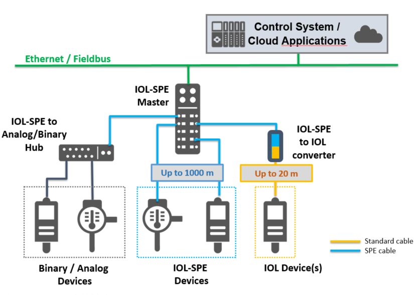
Concept study - IO-Link over SPE Version 1.00
_____________________________________________________________________________________________________
distinguishing feature is that it supports multi-drop configuration with up to eight nodes attached
to the same cable using half-duplex communications.
Multi-drop 10Base-T1S uses a special technique called PLCA, which is an extension of
CSMA/CD and allows devices to avoid collisions altogether. This technique is implemented at
the PHY and appears transparent to devices that are using it , but at the expense of slight
reduction in overall data throughput.
Because power delivery for 10Base-T1S in multi-drop configuration is not specified at this time,
multi-drop configuration is not yet suitable for IO-Link adaptation.
10Base-T1S can also be used in point-to-point with PoDL in either half-duplex or full-duplex
mode. However, the distance specified by the standard for this PHY, 15 meters, is less than
the current IO-Link cable length specifications. This significantly reduces the benefits of
adapting IO-Link for use with T1S PHY but does not preclude it altogether.
1.2.3 Advanced Physical Layer - APL
APL is the current standardization approach for bringing Ethernet to field level in process
automation. This activity is a collaboration between the fieldbus organisations FieldComm
Group, ODVA and PI as well as 11 leading companies in the field of process automation.
APL is a definition of a physical layer based on SPE 10Base-T1L, which is suitable for
applications in explosion hazardous areas. APL is standardized in IEEE 802.3cg as an
additional physical layer.
In comparison to SPE 10Base-T1L, APL uses PAM3 pulse amplitude modulation with 4B3T
coding. Four data bits are represented by a ternary signal (+, 0, -), which reduces the required
bandwidth. The encoder adapts the ternary code in the way that DC offsets are minimized.
The key features of APL are:
Communication and optional power over 100 Ω, 2-wire shielded twisted pair cable
10 Mbps full-duplex communication
Cable length up to 1000 m
Support of intrinsically safety for zones and divisions
Use of industrial graded connectors
An extension of APL with a 100 Mbps full-duplex communication and cable length of up to 200
m is in preparation.
1.2.4 Using 10Base-T1L for IO-Link
As can be seen from its description, 10Base-T1L physical layer provides features that are either
comparable to or exceed in functionality of the existing standard IO-Link physical layer. Areas
of functional overlap include the following:
Simple cabling
Power and data delivery over the same cable
Star topology
Device power control from the single central location
Point-to-point communications between the switch (IO-Link Master) and devices
Long range to accommodate sensor placement
Because of this functional overlap, it is possible to envision a system where the IO -Link physical
layer is replaced with SPE 10Base-T1L, while preserving the functionality and implementation
of core IO-Link technologies such as communications stacks.
Due to the similarity of SPE 10Base-T1L and APL, the same accounts for a replacement of the
IO-Link physical layer with APL. This approach provides the potential of using IO-Link
communication even in intrinsic safety applications.
Figure 1 shows the required modifications within the layer structure.
_____________________________________________________________________________________________________
© Copyright IO-Link Community 2020 - All Rights Reserved Page 5 of 20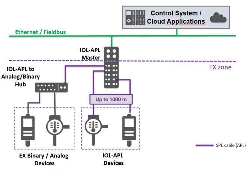
Concept study - IO-Link over SPE Version 1.00
_____________________________________________________________________________________________________
Figure 1 – Physical Layer modification
To the existing IO-Link Master and Device stack implementations, this new physical layer will
provide functionality that is largely identical to the IO-Link physical layer and will incorporate
existing IO-Link functions such as:
Power control to the Device
Device discovery
Transmission of IO-Link frames between the Master and the Device
Additional details of this approach are provided in the sections below.
1.3 Ethernet Frame
Ethernet Frame is defined as a Data Link Layer protocol data unit. That is, data on Ethernet
physical layer is transported as packets, where each packet consists of a single Ethernet frame.
There are several Ethernet frame types, with the most common type being Ethernet II. This
frame type is illustrated in figure 2.
Figure 2 – Ethernet II Frame
All Ethernet frames are characterized by a 6-byte source and destination addresses, EtherType
and a 4-byte checksum.
Please note that preamble and start-of-frame delimiter that are present at the beginning of the
physical layer Ethernet transport, and the inter -frame gap at the end of the physical layer
Ethernet transport have been excluded, for c larity. Also not shown is the optional 4-byte VLAN
(802.1Q) tag. This field is not relevant for the purpose of this discussion.
1.4 EtherType
EtherType is a two-octet (2-byte) field in the Ethernet frame. It is used to specify which high-
level protocol is being encapsulated by Ethernet frame. EtherType field is always located right
before the frame payload, as shown in the following figure.
_____________________________________________________________________________________________________
© Copyright IO-Link Community 2020 - All Rights Reserved Page 6 of 20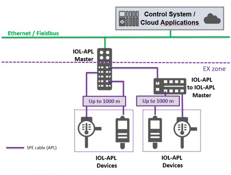
Concept study - IO-Link over SPE Version 1.00
_____________________________________________________________________________________________________
Figure 3 – EtherType
Some of the well known Internet and Fieldbus EtherType values are:
IPv4, 0x0800
Profinet, 0x8892
EtherCAT, 0x88A4
1.5 IO-Link integration with Ethernet
IO-Link integration with Ethernet relies on utilizing a new EtherType, which will be allocated
specifically for the use of IO-Link community. This custom EtherType will allow the delivery of
the Ethernet packet in which it is used directly to the IO -Link stack.
This approach provides for a much simpler and smaller implementation than the more traditional
Ethernet fieldbus implementations that rely on Internet Protoc ol suite (TCP/IP, UDP/IP, etc.) for
communications. It can be implemented in microcontrollers with a very small memory and
persistence footprint and that meet the overall IO -Link goals of low-cost and lightweight
implementation.
Figure 4 shows the layer structure for Master and Devices with the Ethernet physical layer.
Figure 4 – IO-Link stack representation
Using this design approach, only the Physical Layer is replaced. The rest of the IO -Link
implementation, including Application and Master and Device stacks with IO-Link Data Link
Layer remains unchanged.
From figure 4, it can be seen that an additional software component, Ethernet -to-IO-Link
adapter, is necessary to accommodate the transition to the new Ethernet physical laye r. This
adapter allows to avoid changes in the IO-Link Master and Device stacks, and is meant to
provide functionality that is currently available in IO -Link physical layer, such as:
Device power control
Device discovery
IO-Link frame transfer
Device power control is performed on request from the IO-Link Master stack. The adapter
provides the necessary interface between the low -level Master power control interface and the
SPE PoDL functions that control the power to the Ethernet port.
_____________________________________________________________________________________________________
© Copyright IO-Link Community 2020 - All Rights Reserved Page 7 of 20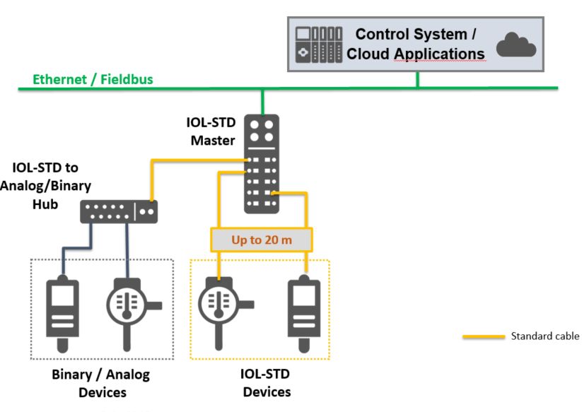
Concept study - IO-Link over SPE                                                        Version 1.00
_____________________________________________________________________________________________________

Device wake-up takes the form of Device discovery. It is performed in the adapter layer and
can consist of initial message exchange and validation between the Master and the Device after
the IO-Link Device boots up.
After the power-up and wake-up/discovery, the adapter reports the presence of communications
link to the IO-Link stack. From there on, the exchange can follow the rules outlined in the IO -
Link specifications.
Another major function of the adapter is to encapsulate the IO -Link frame within the Ethernet
frame while it is sent over the new Ethernet physical layer.
Several ways are possible to achieve this encapsulation. A sample approach is illustrated figure
5. In all cases, to conform to IO-Link specifications, there is a one-to-one correspondence
between the IO-Link and Ethernet frames.

                                 Figure 5 – IO-Link Ethernet frame

Encapsulation can consist of a fixed-length, versioned header that describes the IO -Link frame
contained in the payload, followed by the IO-Link frame. A sample header is illustrated in figure
6.

                                 Figure 6 – IO-Link payload header

An IO-Link frame can then be carried completely intact, without any modifications from its
current form, apart from the timing. If the resultant encapsulated data is smaller than the
minimum Ethernet payload, the adapter layer can add padding to the data accordingly.

_____________________________________________________________________________________________________

© Copyright IO-Link Community 2020 - All Rights Reserved                                 Page   8 of 20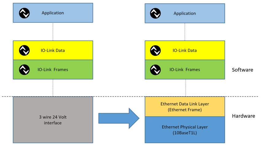
Concept study - IO-Link over SPE                                                        Version 1.00
_____________________________________________________________________________________________________

                                      Figure 7 – IO-Link payload

1.6 Topologies
The typical IO-Link topology in standard automation systems is well known and established.

                               Figure 8 – IO-Link standard topology

With the variable transmission rate of the IO-Link communication and a cable length of up to
20 m a broad field of applications are already possible.

_____________________________________________________________________________________________________

© Copyright IO-Link Community 2020 - All Rights Reserved                                 Page   9 of 20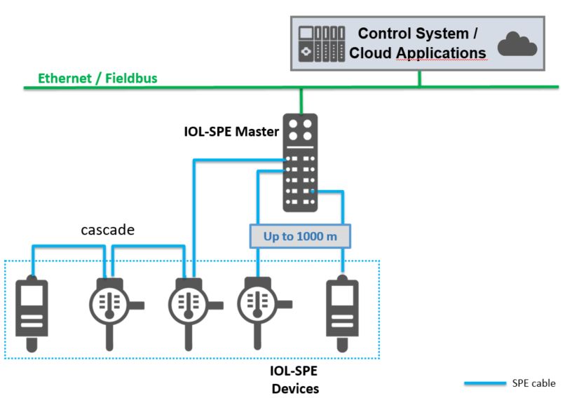
Concept study - IO-Link over SPE Version 1.00
_____________________________________________________________________________________________________
1.6.1 Proposed IO-Link SPE topology
By changing the physical layer form the IO-Link standard to SPE, the possible topology will
remain widely unchanged. The range for IO-Link Devices attached over a SPE connection,
however, extends to up to 1000 meters.
Figure 9 – IO-Link topology using SPE physical layer
As in IO-Link standard applications, I/O-hubs are also possible with IO-Link SPE, offering even
more benefits due to lower possible cycle times and an increased distance range.
An additional option is a converter from IO-Link SPE to the standard IO-Link wiring, which allows
using standard IO-Link Devices attached to an IO-Link SPE Master.
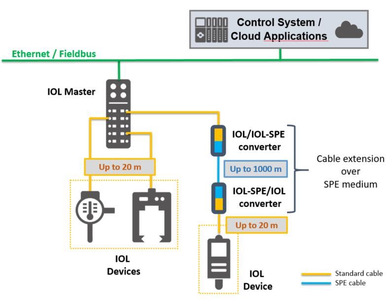
1.6.2 Proposed IO-Link topology with range extension
The introduction of an IO-Link SPE physical layer addresses as well requirements for an
extended distance range for Device connection in standard IO-Link environments.
_____________________________________________________________________________________________________
© Copyright IO-Link Community 2020 - All Rights Reserved Page 10 of 20Concept study - IO-Link over SPE Version 1.00
_____________________________________________________________________________________________________
Figure 10 – Standard IO-Link topology with SPE based range extension
With two converters - from IO-Link standard to IO-Link SPE and back – it is possible to attached
standard IO-Link Devices over a distance of up to 1000 meters distance to the IO -Link Master.
This topology has similar characteristics as existing IO -Link repeater solutions, but offers by far
wider distances between Master and Device.
1.6.3 Proposed IO-Link APL topology
One important extension in the range of IO-Link applications is offered by making use of the
APL (Advanced Physical Layer) interface definitions and hardware. This makes IO -Link
communication possible in explosion hazardous areas, while the topologies of the IO -Link
standard as well as IO-Link SPE system are preserved.
_____________________________________________________________________________________________________
© Copyright IO-Link Community 2020 - All Rights Reserved Page 11 of 20Concept study - IO-Link over SPE Version 1.00
_____________________________________________________________________________________________________
Figure 11 – IO-Link topology using APL
The definition of APL allows use in intrinsic safety applications from Ex Zone 2 down to 0.
In analogy to IO-Link standard and IO-Link SPE, IO-Link APL as well offers the possibility of
providing a hub structure. These hubs allow the connection of legacy intrinsic safe field devices.
The process data of these Devices are transmitted over IO-Link APL communication from the
hub to the Master.
Another possibility using IO-Link APL is intended for applications, where only one or few devices
need to fulfill the intrinsic safety requirements, as shown in figure 12.
_____________________________________________________________________________________________________
© Copyright IO-Link Community 2020 - All Rights Reserved Page 12 of 20Concept study - IO-Link over SPE Version 1.00
_____________________________________________________________________________________________________
Figure 12 – IO-Link standard to IO-Link APL converter
An IO-Link standard to IO-Link APL converter allows the connection of one IO-Link APL field
device. The converter, of course, needs to fulfill all requirements for intrinsic safe power delivery
and isolations.
1.7 Comparison of IO-Link Standard vs. IO-Link SPE/APL
Using Ethernet 802.3 for the physical layers and transmitting native IO-Link frames has some
impact regarding distances, communication startup and compatibility to SIO modes.
SPE benefits:
No wake up procedure to start communication (leads to lean protocol stacks)
Shorter process data cycles even at 10Mbit/s speed
Cable length up to 1000 meter possible
Possible addressing of more than one device
IO-Link Standard (3-wire) IO-Link SPE/APL
Connector M12,M8,M5, wires Not yet defined
Power supply included included
Port Classes A,B “A” only
SIO Mode yes no
Communication startup Wake-up no Wake-up required
Process data cycles typical 2.3 ms (for 38k4 kBaud) less than 0.1 ms (for 10 Mbit/s)
aprox. 1.0 ms (for 230.4 kBaud)
Max. cable length 20 meter 1000 meter
Transmission speed 4.8 / 38.4 / 230.4 kBaud 10 / 100 / 1000 Mbit/s
2 Protocol extensions
The goal of this chapter is to describe some of the potential and future IO -Link protocol
enhancements that can occur if a faster and higher bandwidth physical layer is adapted for use
with IO-Link. It does not make any assumptions about the preservation of or backward
compatibility to the existing protocol implementation. Instead, it tries to document some of the
future additions that have been envis ioned at the time of this writing.
Enhancements listed in the following sections do not necessarily have any correlation with each
other, nor are they necessarily mutually exclusive.
2.1 IO-Link Ethernet Frame Size
Existing maximum IO-Link frame size is an excellent compromise between the needs of small
devices and the desired process data cycle time.
With a faster physical layer like Ethernet, it may be possible to increase the size of the IO -Link
frame, also increasing the size of process data without adve rsely affecting the cycle time.
This will allow devices that have higher process data bandwidth requirements, like RFID or
barcode readers, to be adapted to use IO-Link. Higher bandwidth will also significantly speed
up some of the fundamental functions outlined in BLOB Transfer and Firmware Update Profile
document.
_____________________________________________________________________________________________________
© Copyright IO-Link Community 2020 - All Rights Reserved Page 13 of 20Concept study - IO-Link over SPE Version 1.00
_____________________________________________________________________________________________________
2.2 Device addressing
Current IO-Link protocol is point-to-point. Device addresses are not explicitly specified in the
protocol frame. However, devices can still be addressed directly from the con trol system using
a unique Master identifier and a physical Master port number to which the Device is attached.
This arrangement permits the control system to identify a specific IO -Link Device but allows
only one Device per Master port.
With the larger overall data capacity of the Ethernet frame (up to 1500 bytes), it is possible to
use this extra capacity to introduce secondary Device addressing. This secondary addressing
can allow multiple Devices to be accessed through a single IO-Link Master port. It should be
reiterated that introduction of any kind of new addressing scheme will cause significant changes
to the IO-Link system design and the existing IO-Link to Fieldbus mappings.
Secondary Device addresses can be added to the IO-Link Ethernet payload header, example
of which was given in chapter 1.5. The following figure shows an example of such expanded
payload header that can accommodate multiple frames of variable size.
Figure 13 – Sample header structure accommodating multiple IO-Link frames
One of the ways of implementing secondary addressing is to introduce a notion of a virtual port.
A virtual port is a unique address used to differentiate multiple Devices that are connected to a
single physical port on the Master.
A virtual port identifier can be produced in several ways, depending on the specific topology:
Assigned during Device discovery by the IO-Link Master
Ethernet device MAC address can be read from the device during discovery
In case of aggregation, aggregator physical port number can be used
Using virtual port addressing, Devices can be accessed either directly or through a Device
aggregator.
2.2.1 Direct Device addressing
The example of direct Device addressing can be seen in 10Base-T1S multi-drop topology.
Multiple Devices share the same physical connection to a Master port over the same single-
pair cable. Example of such a topology is given below in figure 1 4.
_____________________________________________________________________________________________________
© Copyright IO-Link Community 2020 - All Rights Reserved Page 14 of 20Concept study - IO-Link over SPE Version 1.00
_____________________________________________________________________________________________________
Figure 14 – IO-Link SPE topology with multi-drop approach
When the controller system needs to identify a specific Device, it can distinguish it by using a
unique Master identifier, Master physical port number and the Device virtual port identifier.
It should be noted, that in case of direct Device addressing there is a one-to-one
correspondence between that IO-Link frame and the Ethernet frame: a single Ethernet frame
encapsulates a single IO-Link frame.
2.2.2 Multiple Device aggregation
In case of aggregation, IO-Link Devices are not attached directly to the Master po rt. Instead,
an intermediate infrastructure component – called ‘aggregator’ - is placed between the IO-Link
Master connected to a Fieldbus and the IO-Link Device.
Examples for aggregator topologies are shown in figure 15 and figure 16 below.
_____________________________________________________________________________________________________
© Copyright IO-Link Community 2020 - All Rights Reserved Page 15 of 20Concept study - IO-Link over SPE Version 1.00
_____________________________________________________________________________________________________
Figure 15 – IO-Link standard to IO-Link SPE aggregator
Figure 16 – IO-Link APL aggregator
The aggregator is not an IO-Link hub. It uses IO-Link SPE or APL to communicate with the
Master. The communication with the Devices uses either IO-Link standard or IO-Link SPE/APL.
_____________________________________________________________________________________________________
© Copyright IO-Link Community 2020 - All Rights Reserved Page 16 of 20Concept study - IO-Link over SPE Version 1.00
_____________________________________________________________________________________________________
The aggregator combines IO-Link frames it receives from Devices into a single Ethernet frame
and sends this frame to the Master. Master responds with a similar compound frame. Upon
receipt of this compound frame, the aggregator separates it into individual IO-Link frames and
sends them to the appropriate Device.
Each Ethernet frame sent between the Master and the aggregator contains IO-Link frames for
all Devices that are attached to the aggregator. The aggregator provides a routing path between
the Master and Devices and may or may not interpret these frames. As of this writing, it is
assumed that the aggregator will be based on a partial IO-Link Master stack functionality.
To address IO-Link Devices attached to the aggregator, aggregator physical port numbers can
be used as a virtual port number.
2.3 Cascading IO-Link Ethernet Devices and deterministic o peration
A different option to connect multiple IO-Link Devices to a single Master port is a cascade
topology. An example of cascade topology is given in figure 17.
Figure 17 – IO-Link SPE topology with cascading approach
In a cascade topology, each Device has two Ethernet connectors, and Devices are daisy-
chained to each other. All the Ethernet frames on such a network are passing through each
Device and are interpreted by each Device.
Prior to the start of the operation, the Master discovers and counts all the Devices in the chain.
During this discovery process, each Device also learns its position in the chain. This allows
the Master to pre-allocate space for IO-Link frames in the Ethernet frame for each Device in the
chain. This technique can be viewed as a form of Time Division Multiplexing, where each
Device gets a known and pre-allocated transmission time slot, resulting in high degree of
determinism.
The compound Ethernet frame sent and received by the Master contains multiple IO-Link
frames, one for each Device in the chain.
There is no explicit Device addressing used in this topology. Addressing is implied, and Devices
are addressed positionally instead: the first IO-Link frame placed in the Ethernet frame is meant
_____________________________________________________________________________________________________
© Copyright IO-Link Community 2020 - All Rights Reserved Page 17 of 20Concept study - IO-Link over SPE Version 1.00
_____________________________________________________________________________________________________
for the first Device in the chain, closest to the Master, the second IO -Link frame for the second
Device, etc., and the last IO-Link frame in the Ethernet frame for the last Device.
The advantage of this approach is response determinism and performance. With appropriately
selected and/or custom-designed hardware, Ethernet frame propagation and IO-Link frame
removal/insertion operations can be performed at nearly the line speed, making this approach
suitable for closed-loop control applications.
2.4 Time stamp
For the purpose of this document, it is proposed that time stamping is implemented as part of
the future meta-data section in the IO-Link Ethernet encapsulation header.
2.5 Time Sensitive Networking (TSN)
TSN is a layer 2 technology. It now becomes possible to extend TSN down to individual Devices
over the IO-Link SPE connection.
3 Application examples
The additional features provided by IO-Link SPE or APL allow an extension of the possible
range of applications.
3.1 Range extension
All applications requiring more than 20 meters distance between Master and Device can now
be solved by IO-Link SPE with or without IOL/SPE converter. Typical application areas are high
bay warehouse shuttles with sensors onboard or distributed sensors for level monitoring in tank
facilities.
3.2 Control loops / motor feedback
By using SPE with 100Mbit/s transmission speed or even in future 1Gbit/s for IO-Link
communication, it will be possible to replace traditional motor feedback interfaces in order to
control high dynamic motor application. This may be done by TDM (Time Divisi on Multiplex) or
optional TSN (Time Sensitive Networks).
3.3 Intrinsic safe areas
Special applications targeting environments with ATEX requirements can be solved by use of
IO-Link APL interfaces as a specialized version of SPE.
Figure 18 – ATEX application
_____________________________________________________________________________________________________
© Copyright IO-Link Community 2020 - All Rights Reserved Page 18 of 20Concept study - IO-Link over SPE Version 1.00
_____________________________________________________________________________________________________
3.4 Conveyor application
Within conveyor applications, usually longer distances than 20 meter are required. This can be
solved by using an IO-Link standard to IO-Link-SPE converter or by using a cascaded topology.
Typical applications are band conveyer e.g. in cement production plants or conveyer used in
warehousing and package distribution hubs.
4 Conclusion
The proposed approach combines the benefits of IO -Link and SPE/APL standards.
The key features and advantages are:
Range - cable length up to 1000 meters
Speed - more than 20 times faster than COM2 (200 times faster with 100 Mbit)
Application - potential support for control loop applications
Application - intrinsically safe applications with APL
Compatibility - simplicity of IO-Link integration and existing tools are unchanged
Scalability - possibility for topology extensions
Security – reduced security requirement by avoiding TCP/IP in implementation
All aspects of the IO-Link data model are preserved, ensuring easy and seamless integration
with existing tools and automation systems, while opening the door to a broad range of new
applications.
_____________________________________________________________________________________________________
© Copyright IO-Link Community 2020 - All Rights Reserved Page 19 of 20Concept study - IO-Link over SPE Version 1.00
_____________________________________________________________________________________________________
Copyright by:
IO-Link Community
c/o PROFIBUS Nutzerorganisation e.V.
Haid-und-Neu-Str. 7
76131 Karlsruhe
Germany
Phone: +49 (0) 721 / 96 58 590
Fax: +49 (0) 721 / 96 58 589
e-mail: info@io-link.com
http://www.io-link.com/
_____________________________________________________________________________________________________
© Copyright IO-Link Community 2020 - All Rights Reserved Page 20 of 20You can also read